Week -2
ANS1.
THEORY:
- The objective is to make a Simulink model of Doorbell using solenoid , a doorbell ckt with solinoid may consists of a battery , a switch , a plunger and a bell in a closed ckt which is recognized from the reference figure from the question.
- Now whenever the switch is closed the electromagnet recieves electrical power(VDC) from the battery and move the plunger to hit the bell which producing sound.
- The switch is NO(normally open) in ideal state. BY an external physical force actig upon the switch for 2 sec thus it will be NC(Normally closed) state for 2 sec and then again returning to ideal state. This condition will be applied in the simulation.
- In simple terms a doorbell will resonate for 2sec fron an ideal state.
BLOCkS USED IN MODEL:
- Pulse generator:
With the help of this block we can generate the desired frequency.
- Switch:
The block represents a switch controlled by an external physical signal. If the external physical signal PS is greater than the threshold, then the switch is closed, otherwise the switch is open.
- DC source:
The DC Voltage Source block maintains a time-invariant (constant) voltage across its output terminals, independent of the current through the source.
- Solinoid: A solenoid is a device comprised of a coil of wire, the housing and a moveable plunger. When an electrical current flows through this wire, a strong magnetic field is created.
- Ideal translational motion sensor:
This block measures velocity or displacement in a mechanical translational network.
- Simulink to PS converter
- PS converter to simulink
- Electrical reference:
Electrical ground.
- Mechanical translational reference:
This block represents a mechanical translational reference point, that is, a frame or a ground.
- Solver configuration:
Defines solver settings to use for simulation.
- Scope: This block used to observe the o/p curve.
SIMULINK MODEL EXPLAINATION
- Pulse generator producing the required pulse which is a square wave freq. with 2sec of pulse delay , time period as 4sec and pulse width is half.
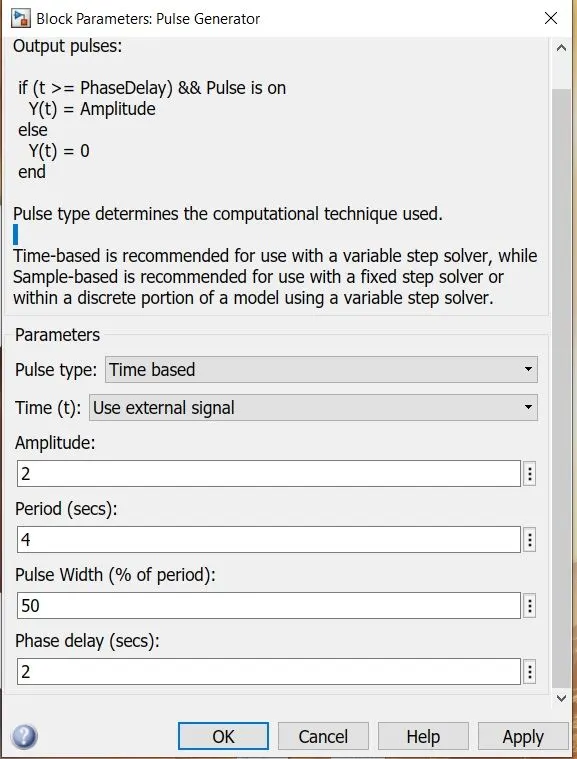
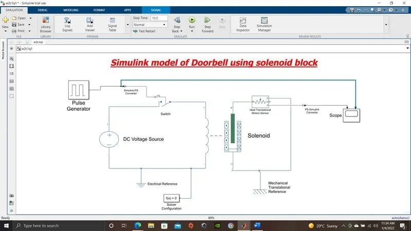
- The same signal is fed to the physical signal port of the switch after converting through simulink to PS converter.
- The switch is connected to the positive node of a dc source.(let asume 110VDC was given)
- The switch is also connected to solinoid.
- Ideal translational motion sensor block is used to observe the motion of the plunger.
- Electrical and mechanical reference blocks , and PS to simulink or simulink to PS blocks were required because this model is interconnected between electrical , mechanical and simscape.
- Finaly the output of the motion sensor is fed to scope to observe the curve.
CONCLUTION
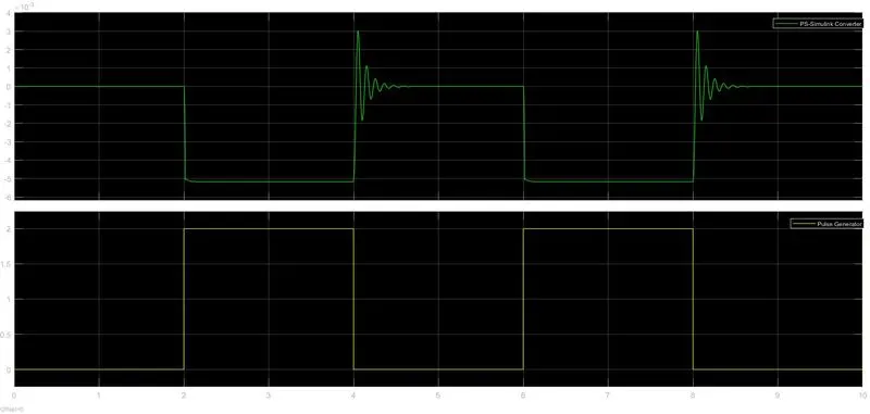
After simulating the above model hence we get the below plot of movement of plunger with respect to time , during 2 to 4sec while the signal is high which means switch is in NC state , movement of the plunger of solinoid can be observed. Again the same can be observed during 6 to 8 sec.
ANS2.
THEORY:
In this study we are using an NTC thermistor to sense the temparature of the heater and autometically turning on or off a fan at perticular temparature. A heat source was given whhich is controlled accordingly,
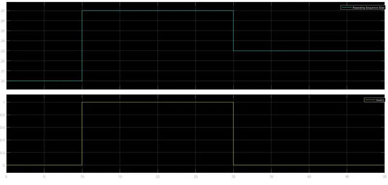
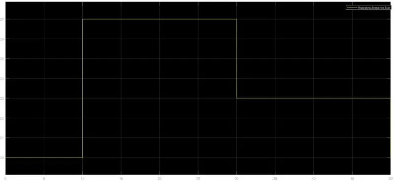
- Temperature source: 20 °C from 0 to 10 seconds, 27 °C from 10 to 30 seconds, 23 °C from 30 to 50 seconds.
- Fan conditions: ON if the temperature above 25 °C, OFF otherwise.
- For an NTC thermistor, as temperature increases, resistance decreases. As for Ohm's law resistance and voltage is proportional. So increase in temperature, voltage will decrease for NTC type thermistor (negative temperature coefficient).
- From above relation , we have to use an voltage sensor fr sensing the voltage across the resistor.
- A switch is used to operate a fan which is autometic. Threshold voltage (the exact voltage across the resistor at 25degC for a for a given source)is used in the switch.
BLOCK USED IN SIMULINK MODEL
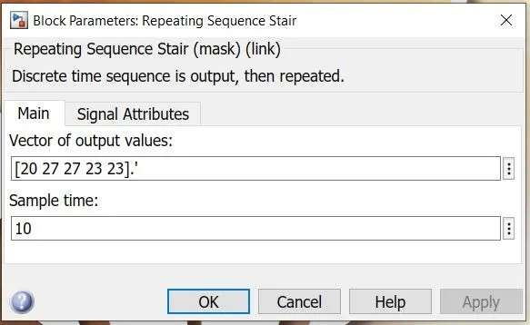
- Repeating sequence stair
Output and repeat discrete time sequence. Output values taken 20 27 23 23 23 to avail the given condition.
temperature/time graph from the above i/p
- Controlled temperature source
This block represents an ideal energy source in a thermal network that can maintain a controlled temperature difference regardless of the heat flow rate.
- Thermal reference
This block represents a reference point in a thermal network where the temperature is equal to absolute zero.
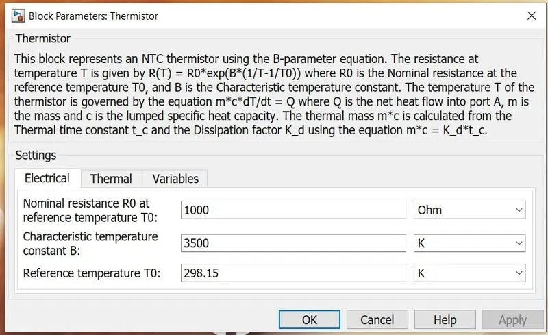
- Thermistor
This block represents an NTC thermistor with 1000 ohm resistance acts on reference temp 25degC.
- Solver configuration
Defines solver settings to use for simulation.
- Battery
A block models a battery. voltage = 12Vdc , internal resistance = 2 ohm
- Resistor
This block models a resistor with optional tolerance, operational limits, fault and thermal noise modeling.
- Voltage sensor
The block represents an ideal voltage sensor, that is, a device that converts voltage measured between any electrical connections into a physical signal proportional to the voltage.
- Electrical reference
The Electrical Reference block represents an electrical ground
- Simulink to ps converter
Converts the Simulink input signal to a Physical Signal.
- PS to simulink converter
Converts the input Physical Signal to a Simulink output signal.
- Switch
The switch we used includes 2 data i/p port(which is 1st and 3rd) and 1 control i/p( which is 2nd) port and 1 data o/p port. 1Pass through input 1 when input 2 satisfies the selected criterion; otherwise, pass through input 3. The criteria for control port 2 are u2 >= Threshold.
- Constant
A constant value.
- Display
Display input values.
- Scope
Display output graph.
MODEL DETAILS
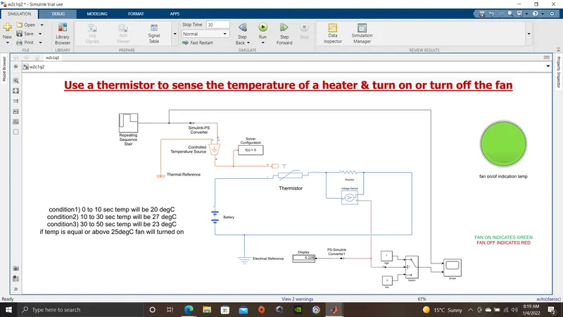
- From the theory mentioned above below simulink model is made. the above mentioned blocks are used in this model.
- The main goal is to control a fan with thermistor in different temperature scenario.
- A repeating sequence stair block is used to build a signal which approves the condition which is , for temperature 20 °C from 0 to 10 seconds, 27 °C from 10 to 30 seconds, 23 °C from 30 to 50 seconds.
- A dc source is connected to thermistor.(A 12 VDC battery is used in following model)
- A resistor connected with the thermistor in series to observe the resistance value reacting under different temperature which are 20,27,23 degC accordingly.
- A voltage sensor is connected parallaly with the above mentioned resistor to ovserve the voltage difference under different temperature mentioned above.
- The output of the thermistor is fed to a switch( Pass through input 1 when input 2 satisfies the selected criterion otherwise, pass through input 3.) The criteria or threshold voltage is set to 5.994VDC. That means if the voltage acrross resistor rises above 5.993VDC then input 1 will fed to output of the switch. If the temp is lower than 5.994 VDC then input 2 will fed to output of the switch.
- Likewise when the temperature of the heater is 20 degC which runs first 10 sec,the voltage across resistor is 5.396VDC which is lower than the threshold voltage 5.994 set in the switch the output will fed through 3rd i/p data port. A constant 0 is connected to 3rd data i/p port which refers the fan will kept in off condition.
- Likewise when the temperature of the heater is 23 degC which runs last 20 sec (31 to 50), the voltage across resistor is 5.757VDC which is lower than the threshold voltage 5.994 set in the switch the output will fed through 3rd i/p data port. A constant 0 is connected to 3rd data i/p port which refers the fan will kept in off condition.
- Likewise when the temperature of the heater is 227 degC which runs middle 20 sec (11 to 30), the voltage across resistor is 60228VDC which is higher than the threshold voltage 5.994 set in the switch the output will fed through 1st i/p data port. A constant 1 is connected to 1st data i/p port which refers the fan will kept in on condition.
- The below three simulink blocks represents the same with different run time that is 30 sec, 50 sec, 10 sec accordingly.
- Instead of fan we used a lindication lamp which is red in off and green in on condition.
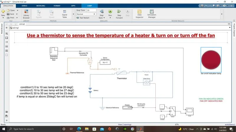

Conclution: Below plot represents the o/p signal from repeating sequence stair and o/p of switch. it's clearly recognized that
- during 0 to 10 sec heater temperature is 20degC and switch signal is low thus fan is off
- during 11 to 30 sec heater temperature is 27degC and switch signal is high thus fan is on
- during 31 to 50 sec heater temperature is 23degC and switch signal is low thus fan is off.