Final Project: Design of an Electric Vehicle
Create a MATLAB model of electric car which uses a battery and a DC motor. Choose suitable blocks from Powertrain block set.
Prepare a report about your model including following:
Objectives:
1. System level configurations
2. Model parameters
3. Results
4. Conclusion
Introduction:-
An electric vehicle (EV) is one that operates on an electric motor, instead of an internal-combustion engine that generates
power by burning a mix of fuel and gases. Therefore, such as vehicle is seen as a possible replacement for current-generation
automobile, in order to address the issue of rising pollution, global warming, depleting natural resources, etc. Though the
concept of electric vehicles has been around for a long time, it has drawn a considerable amount of interest in the past decade
amid a rising carbon footprint and other environmental impacts of fuel-based vehicles.
A new study related to Vehicle/Automobile engineering says that by coming 2025, there will be a major transformation in the
automobile sector. Many automakers are working to change the vehicle technologies, the major area is to decrease the
pollution and use electrification in the upcoming vehicles. The researchers and automakers are continuously working to reduce
CO2 emissions.
New technology like high capacity lithium type battery will be a major energy source for the propulsion of electric vehicles.
Electric vehicles consists of an electric motor that is powered by a battery pack. The main advantage of electric vehicles is that
they emit zero emissions and are eco-friendly. They also do not consume any fossil fuels, hence use a sustainable form of
energy for powering the car. The main components of electric vehicles are :
* Traction battery pack
* DC-DC Converter
* Electric motor
* Power inverter
* Charge Port
* Onboard charger
* Controller
* Auxiliary batteries
* Thermal system (cooling)
* Transmission
The Basic Block Diagram of an EV is given below,
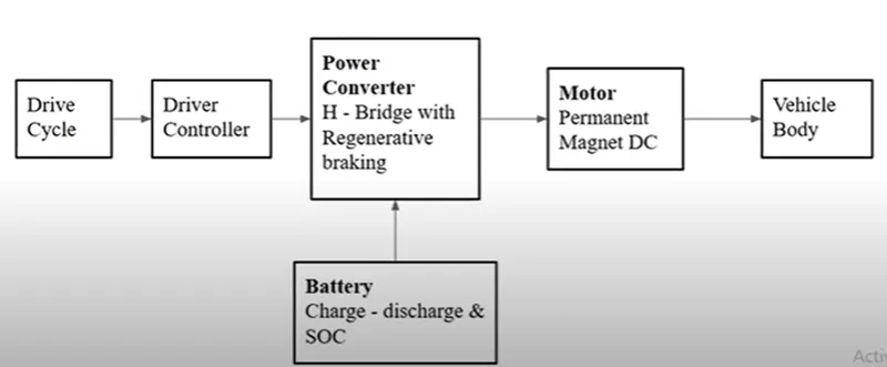
Keeping this model as reference we can build our EV.
System Level Confirguration & Model Parameters:-
Inorder to build a simulink model we have to consider each parts models and to be connect each parts. All the modeling
blocks are already available in simulink library. We consider the each block as follows,
1. Vehicle Body and Tires
We will create a simple car model using SimDriveline library. This block provides components for modeling and 1-D mechanical
system. This model includes vehicle, tires, clutch and transmissions etc.
Considering the folling parameters for the design,
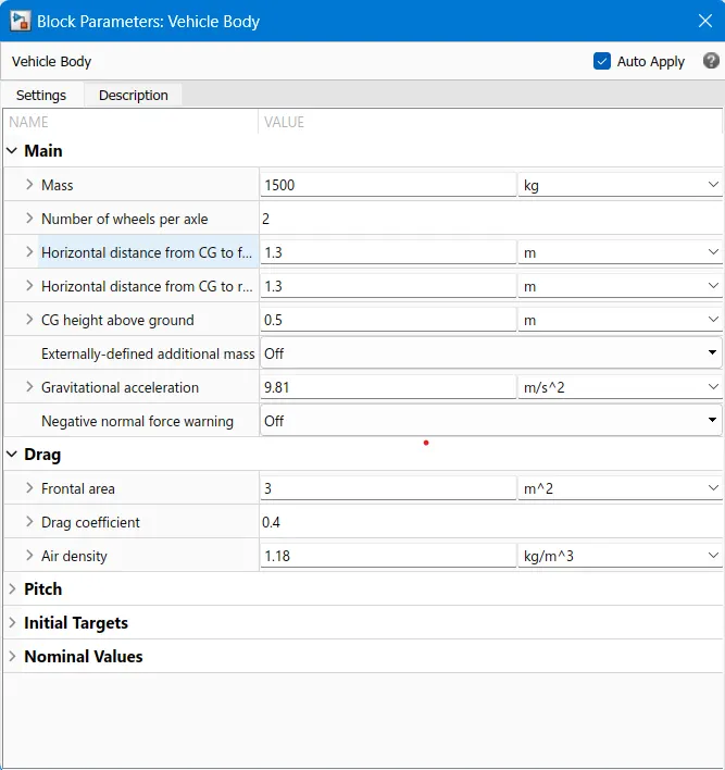
Vehicle Mass = 1500 Kg
Wheels per axle = 2
Frontal Area = 3m^2
Drag Coefficient = 0.4
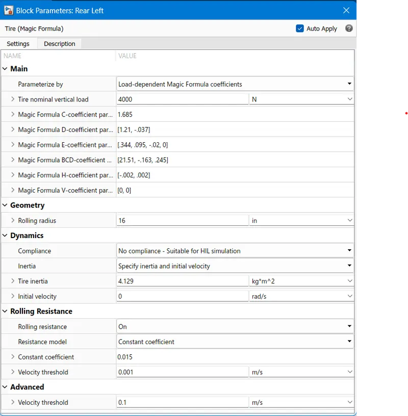
Rolling Radius = 16 inch
Tire Stiffness = 200000 N/M
Tire Damping = 1000 N/(m/s)
Tire Inertia = 4.129 Kg/m^2
Rolling Resistance = 0.015
Road Inclination = 0 Degree
Head Wind Speed = 1 m/s
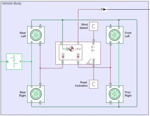
* We start to design by adding the Simscape -> Driveline -> Tires & Vehicle, Vehicle body and Tire(Magic Formula) are added as
below. The unlisted parameters are kept in default values.
The Tire(Magic Formula) is given below,
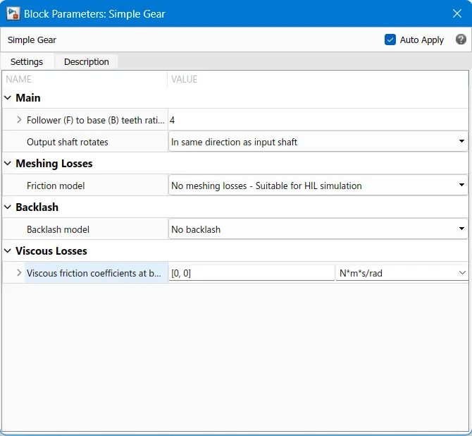
Simple Gear
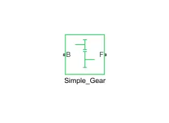
* Simple gear block is used as the gear box with suitable gear ratio of our convenient to achieve the desired output tracking.
I kept the gear ratio as 4 in here.
B: The output B, base gear is connected with the input of DC motor R. It is a Rotational mechanical conserving port.
F: The output of F, follower gear is connected with the rear axle. It is also a Rotational mechanical conserving port.
* The vehicle body block is as given below,
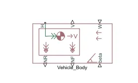
* The Vehicle Body block represents a two-axle vehicle body in longitudinal motion. The vehicle can have the same or a different number of wheels on each axle.
* The block consists of body mass, aerodynamic drag, road incline, and weight distribution between axles due to acceleration and road profile. In optionally we can include pitch and suspension dynamics.
* The block has an option to include an externally-defined mass and externally-defined inertia. The mass, inertia, and centre of gravity of the vehicle body can vary over the course of simulation in response to system changes.
The Vehicle body parameters are as shown in below,
DC Motor
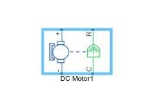
* Here in this system, the positive terminal is connected with the current sensor negative terminal and negative terminal is connected with the negative terminal of H-Bridge.
* R is DC motor rotor which connected with mechanical rotational port i.e. simple gear whereas C is DC motor case and it is connected with mechanical rotational reference.
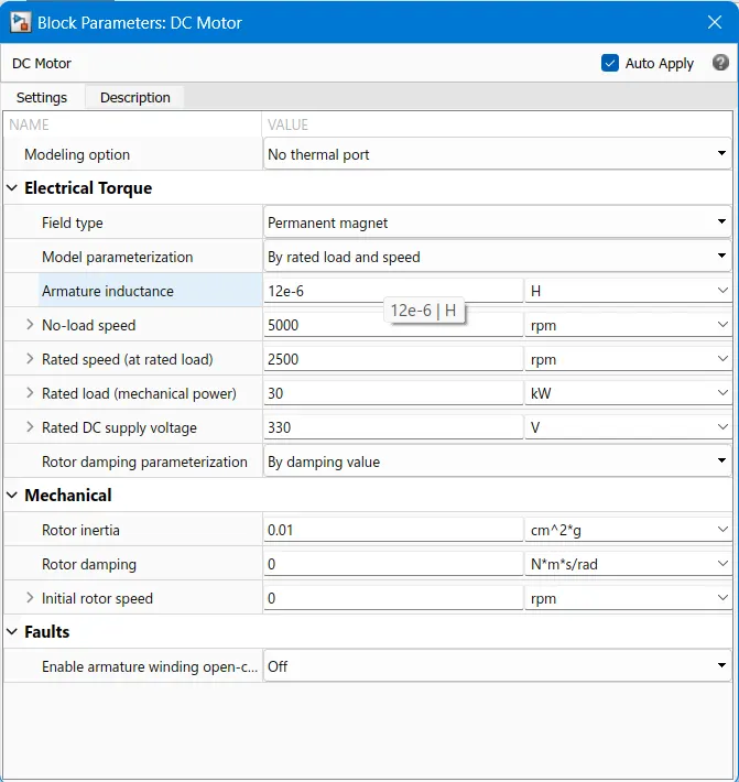
* in here we specifies the moto kW rating and supply voltage. The rated speed are set in here too.
Battery
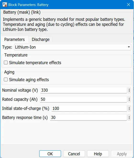
Here we will add a battery system to run the vehicle system and vehicle too. So for that added battery from Simulink library.
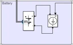
* Inorder to keep its current constant irrespective of the voltage passing through, COntrolled current source is used. I am
taking the battery capacity as 330VDC and with 50Ah.
Bus Selector
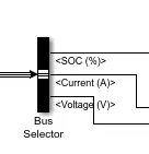
* The Bus selector block is used to seperate the battery parameters and to monitor invidually.
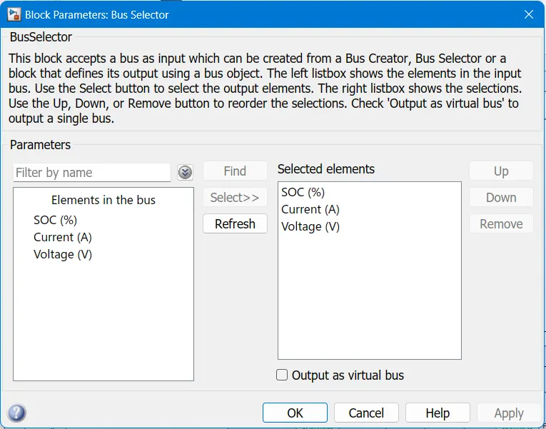
*This block accepts a bus as input which can be created from a Bus Creator, Bus Selector or a block that defines its output
using a bus object.
* The left listbox shows the elements in the input bus. Use the Select button to select the output elements. The right Listbox
shows the selections.
* Use the Up, Down, or Remove button to reorder the selections.
H-Bridge
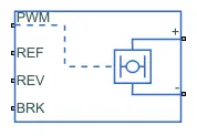
* This block represents an H-bridge motor drive. The block can be driven by the Controlled PWM Voltage block in PWM or
Averaged mode.
* In PWM mode, the motor is powered if the PWM port voltage is above the Enable threshold voltage. In Averaged mode, the
PWM port voltage divided by the PWM signal amplitude parameter defines the ratio of the on-time to the PWM period.
* Using this ratio and assumptions about the load, the block applies an average voltage to the load that achieves the correct
average load current.
* The Simulation mode parameter value must be the same for the Controlled PWM Voltage and H-Bridge blocks.
* If the REV port voltage is greater than the Reverse threshold voltage, then the output voltage polarity is reversed. If the
BRK port voltage is greater than the Braking threshold voltage, then the output terminals are short circuited via
one bridge arm in series with the parallel combination of a second bridge arm and a freewheeling diode.
* Voltages at ports PWM, REV and BRK are defined relative to the REF port.
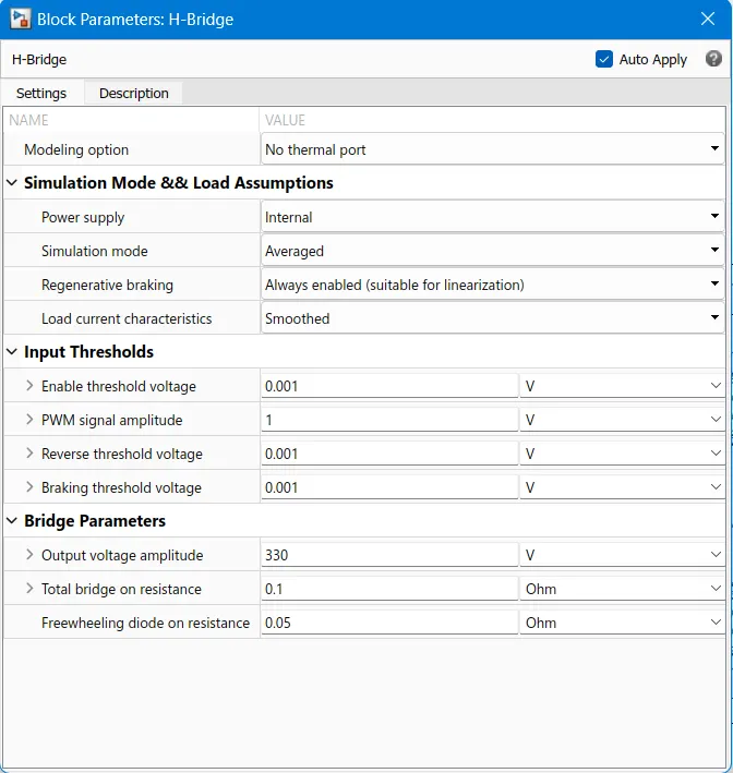
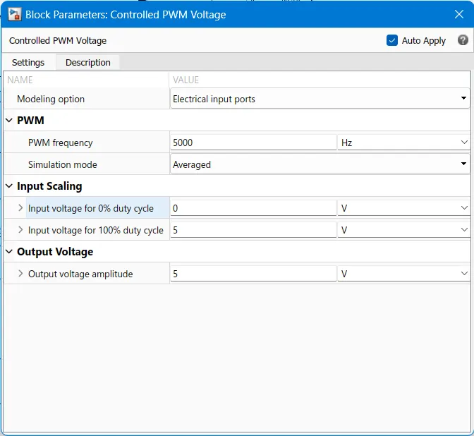
Controlled PWM Voltage
* This block is used to create a pulse-width modulated voltage across through PWM and REf ports. Then output voltage is zero
when the pulse is low and is equal to the output voltage ampiltude parameter with high.
* The Simulation mode is used as averaged to reduce the simulation time.
Longitudinal Driver
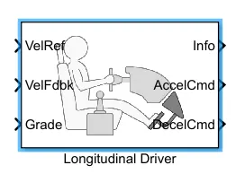
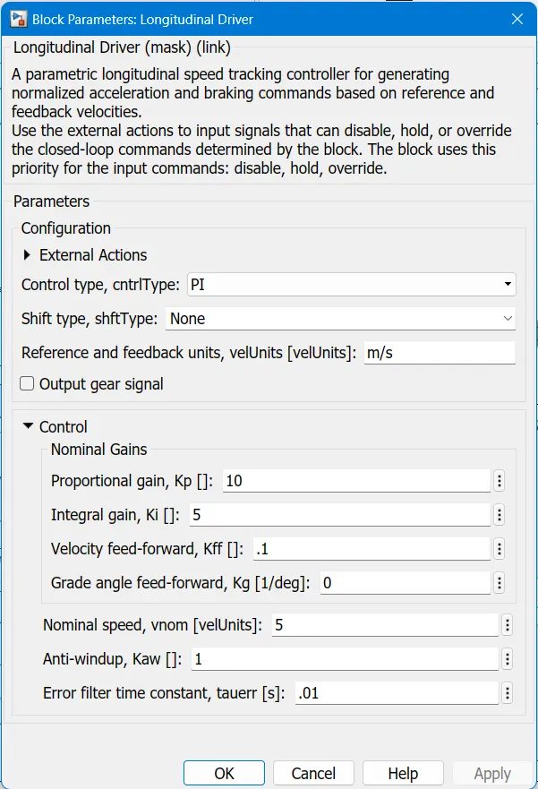
* This block is used for the controlling of the vehicle by giving the drive cyle input as reference and according to that the block
generates the acceleration and braking command.
* The velocity feed back loop is taken for the correction of acceleration command from the final output.
* No parameters are changed in this block and the measurement port(info) is terminated.
* The gradient value is taken as zero and the input given with a constant block.
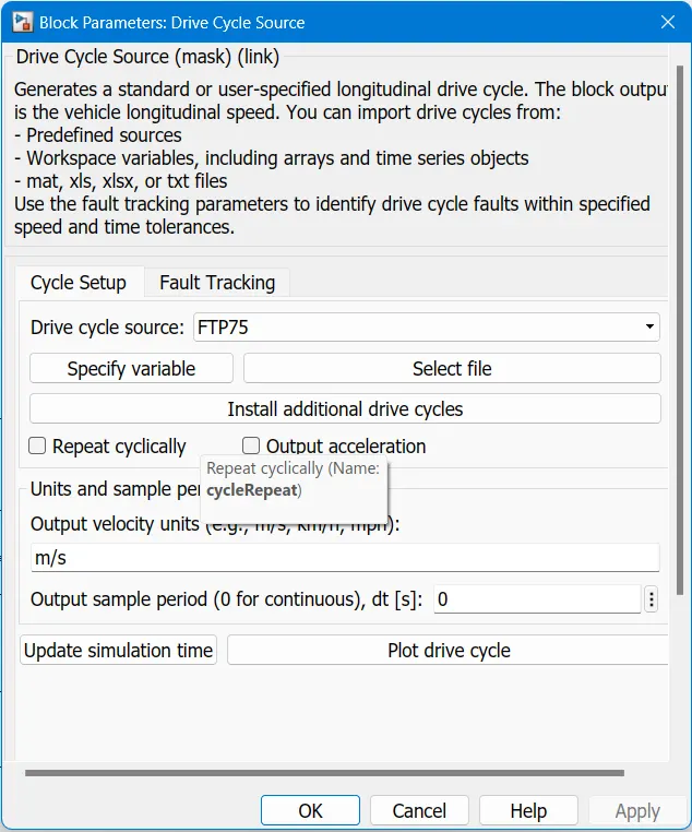
Drive Cycle Source
* The drive cycle source is given as an input for the EV. The FTP75 Drvice cycle having 2747sec running time.
Final Design
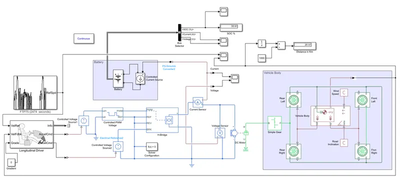
* The final design of my EV as shown in below.
Results:-
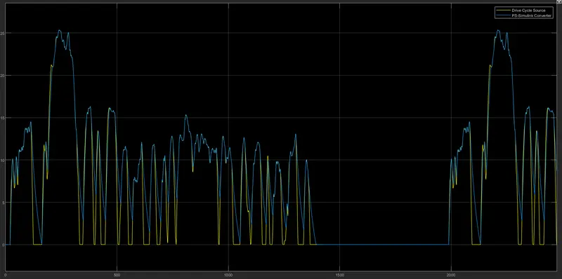
* The plot the we obtained as the result of running the model, Drivecycle vs Output velocity is given below.
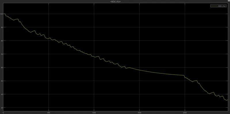
* The SOC % after running the model,
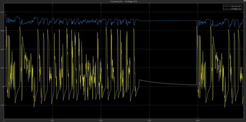
* The voltage and current of the battery,