Final Project: Design of an Electric Vehicle
PROJECT: DESIGN OF AN ELECTRIC VEHICLE
Theory:
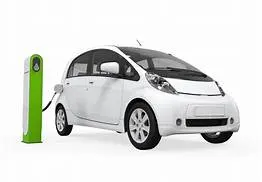
The electric vehicle is a vehicle that runs on electricity alone. Such a vehicle does not contain an internal combustion engine like the other conventional vehicles. Instead, it employs an electric motor to run the wheels. These vehicles are becoming very popular nowadays. They are considered to be a promising solution for the future transportation. The most common example is Tesla.
- An electric vehicle (EV) is one that operates on an electric motor, instead of an internal-combustion engine that generates power by burning a mix of fuel and gases.
- An electric vehicle may be powered through a collector system by electricity from off-vehicle sources, or may be self-contained with a battery, solar panels, fuel cells or an electric generator to convert fuel to electricity.
Electric Vehicles can be broadly classified into 8 different types.
- Plug-in Electric Vehicle
- On- and Off-road Electric Vehicles
- Space Rover Vehicles
- Seaborne Electric Vehicles
- Airborne Electric Vehicles
- Electrically Powered Spacecraft
- Range-extended electric vehicle
- Railborne Electric Vehicles
Types of Electric vehical:
There are mainly three variations of Electric Cars which has been classified by the usage of electricity to fuel. They are:
- Plug-In Electric
- Plug-In Hybrid
- Hybrid-Electric (HEV)
Plug-In Electric
- This runs only on electricity.
- There is no requirement of petrol or diesel.
- There is nil emission produced.
Plug-In Hybrid
- This is powered by electric and by fuel both.
- This can be easily switched between the battery and the fuel engine.
- For battrey operation can be plugged in to charge when needed.
- There is moderate amount of emission produced when used in fuel mode.
Hybrid-Electric (HEV)
- Powered by both fuel and electricity.
- This cannot be plugged in to charge like the regular plug in electric cars.
- These charges through regenerative braking.
Battery Electric Vehicles
- A battery electric vehicle (BEV), pure electric vehicle, only-electric vehicle or all-electric vehicle is a type of electric vehicle (EV) that exclusively uses chemical energy stored in rechargeable battery packs, with no secondary source of propulsion.
- Battery Electric Vehicles (BEV) thus have no internal combustion engine, fuel cell, or fuel tank.
- Some of the broad categories of vehicles that come under this category are trucks, cars,buses, motorcycles, bicycles, forklift etc.
Advantages :
Electric Vehicles – Environmental Advantages
Electric cars (or electric vehicles, EVs) have several environmental benefits compared to conventional internal combustion engine cars.
- Have the potential to reduce greenhouse gas emissions
- Reduce dependence on petroleum
- Reduce health effects from air pollution
- Reduce dependence on petroleum
- They produce little or no tailpipe emissions
Electrical Vehicles – Better Energy Efficiency
- Internal Combustion engines will consume fuel even when the vehicle is stationary, whereas in electrical vehicles, the energy is not consumed when it is stationary.
- Electrical Vehicles ‘tank-to-wheels’ efficiency is about a factor of 3 higher than internal combustion engine vehicles
Electric Vehicles – Mechanical Advantages
- They can be finely controlled and provide high torque from rest, unlike internal combustion engines, and do not need multiple gears to match power curves. Hence it removes the requirement for gearboxes and torque converters.
- Lesser vibration
- Lesser noise
- Electric motors are mechanically very simple and often achieve 90% energy conversion efficiency over the full range of speeds and power output and can be precisely controlled.
COMPONENTS:
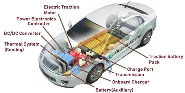
The main components of the EV are:
-
- Battery (All-Electric Auxiliary)
- Charge Port
- DC / DC Converter
- Electric Traction Motor
- On-board Charger
- Power Electronics Controller
- Thermal System (Cooling)
- Traction Battery Pack
- Transmission (Electric)

How does Electric Car Work
- The Electric Cars look the same as any regular fuel generated Cars, however the Plug in Cars don’t have the Tail Pipe and the Gas Tank. The source of the power of the Electric Car is the batteries which act as Gas Tank, supplying the Electric Motors the energy to run the vehicle. The battery’s Electrical energy gets converted in to Kinetic energy by the Motor of an Electric Car.
- The user/driver turns on the car or powers the car. Selects “Forward” or “Reverse” option and steps on the accelerator pedal . Electric motor has only a single rotating element called the Potentiometer. The motion from the motor is transmitted to the car wheels through Controller. The power is controlled by Controller which helps determine which parts or accessories require more power and thereby helps in distribution of the battery energy.
- If the Car has to move “Reverse” then the flow of electricity through the motor is reversed which changes the rotation of the Motor. This makes the wheels to rotate in the opposite direction. The Electric Cars have a Regenerative braking system along with conventional friction braking.
- In Regenerative Braking System, when the User/Driver releases the accelerator pedal and pushes the brakes, the motor acts as a generator and converts Car’s kinetic energy to electrical energy which helps in recharging batteries. This process reduces the speed of the Car. The User can also apply the conventional Friction braking system for stopping the car immediately. The rest of the components like the Air Bags and Air Conditioning is the same as the fuel powered cars.
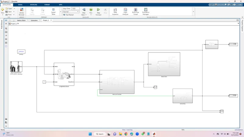
Main simulation diagram:
System level configuration:
System Level Configuration enables the configuration or design of systems of independent components – independent and interdependent, as when the interposition of a valve affects the flow rate in a pipe system. The system must be designed for functionality that is enabled, not by a single configured component, but by the combination of components, and the combination must satisfy engineering constraints.
VEHICLE BODY SUBSYSTEM:
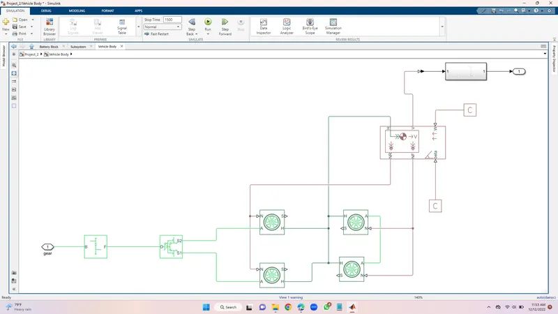
This block contain 6 ports which can be used to model various aspects of the vehicle body. The ports are mentioned below;
- H- This stands for hub and is used to connect the hubs of the wheels to the main body of the vehicle.
- V-Physical signal output port which stands for 'velocity' and is used the output the velocity of the vehicle.
- W- Physical signal input port and allows us to model a wind velocity that acts aginst the vehicle.
- NR- Physical signal output port to connect to connect the rear wheels
- NF- Physical signal output port to connect the front wheels of the vehicle.
- Beta- Physicall signall input port which allows the vehicle to undergo an inclination of hill climbing force.
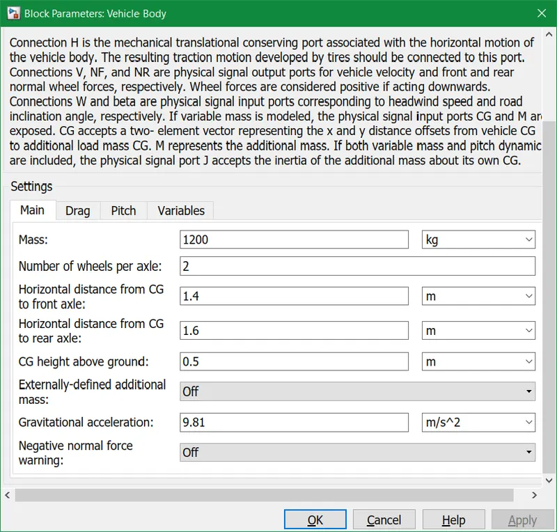
- Model parameters to set up mass, frontal area amd others.
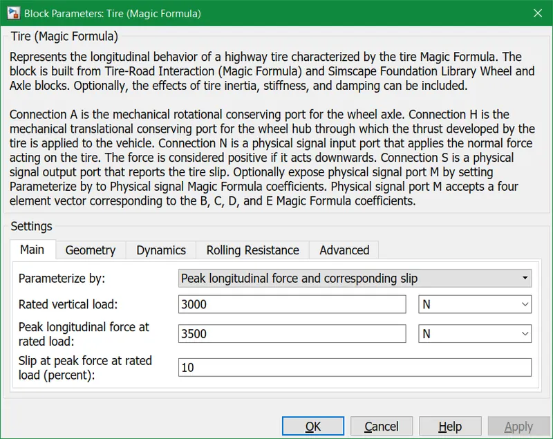
Tire block parameters:
Simple gear block parameters:
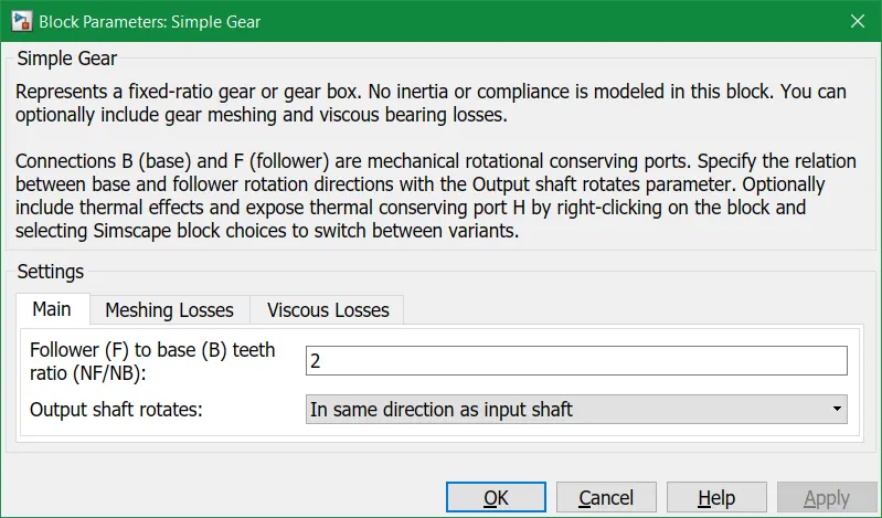
This block models a gear system with fixed gear ratio with no-inertia effects. However, we can modify the messing of the gear teeth, Here The follower to base teeth ratio has been set to 2 and the output shaft rotates in the same direction as the input shaft.
All these blocks are categorised into a single subsystem which we have names as vehicle body block, which takes the mechanical input from the motor and controller block into the gear and displays the velocity at which the vehicle body moves.
MOTOR AND CONTROLLER SUBSYSTEM:
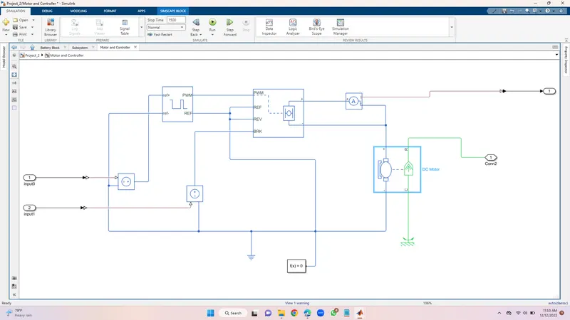
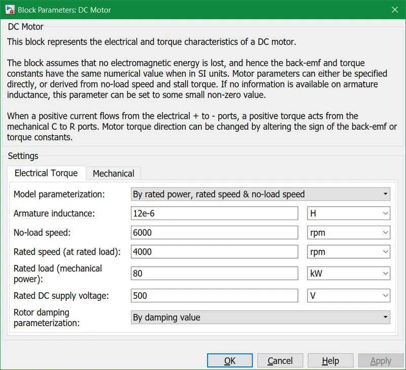
DC-Motor
H-bridge:
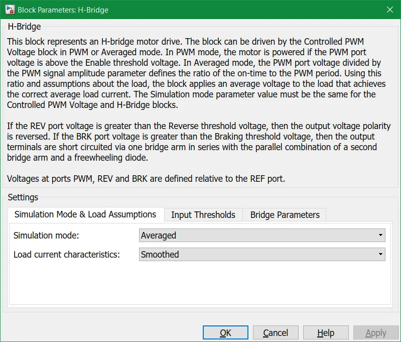
This is a power converter which is needed to provide power of the correct form and magnitude from one component to other. In case of EV,s a power converter is needed to provide a DC voltage from the battery of the EV to the DC motor, so that it can fuction properly at the required parameters.Here i have used an H-bridge motor drive as my power converter. The left side is for controlling the voltage signals and the right side terminals to provide the controlled voltage to the DC motor the left side ports are:
- PWM- Pulse width modulation
- REF- Reference
- REV- Reverse
- BRL- Brake
Controlled PWM voltage :
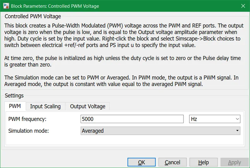
I used a 'controlled PWM voltage' to provide a controlled pulse width modulated voltage to the H-bridge block. The pulses of voltage created by this block are dependent on the duty cycle which is in that ratio of the time that the switch is ON to the time taken for one cycle. The duty cycle formula is given by:- Duty cycle= Ton/Ton +Toff= Ton /Tcyc. where Ton = On time,Tcyc=Time taken for one cycle.
Controlled voltage source:
This block provides the necessary voltage that is powerfull enough to maintaion the voltage at the output regardless of the current that passes through it.In this subsystem control voltage blocks ahve been used . One block is used for acceleration and other to provide the voltage for deacceleration.
Electrical reference block is used to create grounding effect for electrical circuits. In my model, we have used it in 2 parts . First to create an electrical ground between Controlled voltage source, controlled PWM voltage, H-bridge blocks. The second is for the battery system which will be modelled afterwards.
Solver configuration block is used to solve any necessary equations in a model. I Have used them in the connection to the REV port of the H-Bridge block.
Battery Subsystem:
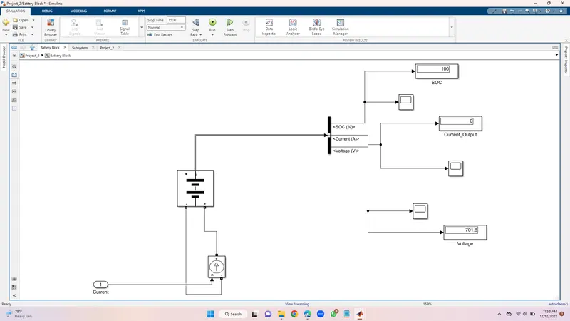
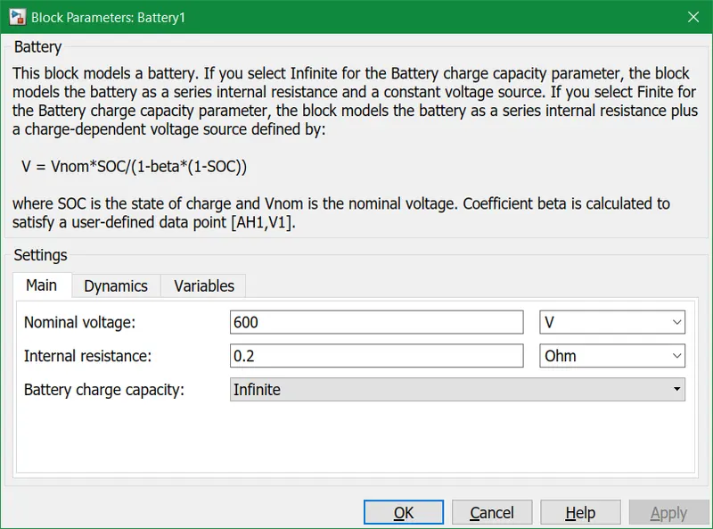
Battery: The battery will be the energy store of the EV and will contain the electrical energy in DC form and provide this energy to operate.
Nominal voltage has been set to 600 volts, internal resistance has been set to 0.2 ohms and an infinite charging capacity
SOC (state of charge) estimate subsystem:
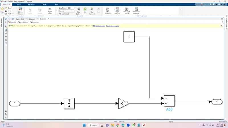
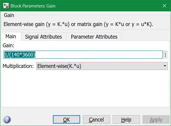
To measure the state of charge of the battery, a sub-system was created of various blocks. The first block is integrator block used to handle data transfer and integrate the value of the current signal with respect to time and next is the Gain block is used in order to multiplyer divide the signal coming from integrator block. This block will divide the current signal with the ampere ratingof battery which is 140(Ah)*3600(secs in hour) . Assuming the battery is always fully charged I have added the constant block with a value of 1 representing 100%.Next a sum block is used to perform addition and substraction operations athese blocks aremade into a subsystem called SOC estimate. A scope block is used at the junction of the PS-simulink converter block to plot the output signall of the current from the battery.
Block parameters of the gain block:
Speed measurement :
In order to measure tyre speed. I have modified the scope block to have two input ports where one port takes the output velocity signal from the vehicle sub-system block and other port takes the output signall from the drive cycle to the reference velocity port on the longitudinal driver block. This has been done to compare the two speeds and check weather they overlap and achieve the same speed.
Distance measurement:
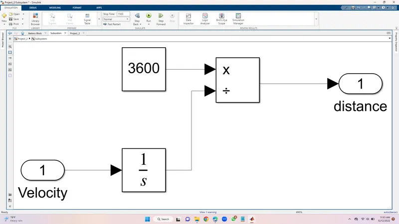
Mathematical blocks and scope block is used to measure the distance travelled by the vehicle. First we had to implement the integrator block to integrate the velocity siganal that is output from the velocity sub-system. Dividen block along with constant block having a value of 3600 is used to divide the integrated speed . This will give us the distance travelled in kilometers.
Longitudional driver and drive cycle:
The longitudinal driver block is used for giving normalized acceleration and deacceleration commants . The ports in this block are:
- Velref- This stands for the reference velocity and it is the velocity data provided from a drive cycle source.
- Velfdbl- This stands for feedback velocity and it is coming from the vehicle's body velocity port
- Grade- This port provides a grade or inclination angle on which the vehicle is travelling in degrees.
- Info- This port is for the bus signals which consists of block calculations
- Accelcmd- This port provides the acceleration command to a controlled voltage source
- Deacclcmd- This port provides the deacceleration command to another voltage source.
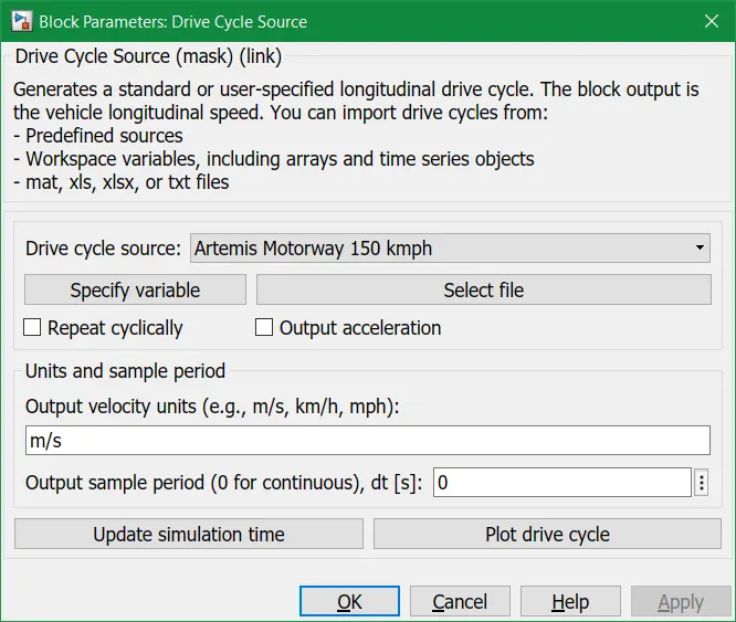
Drive cycle:
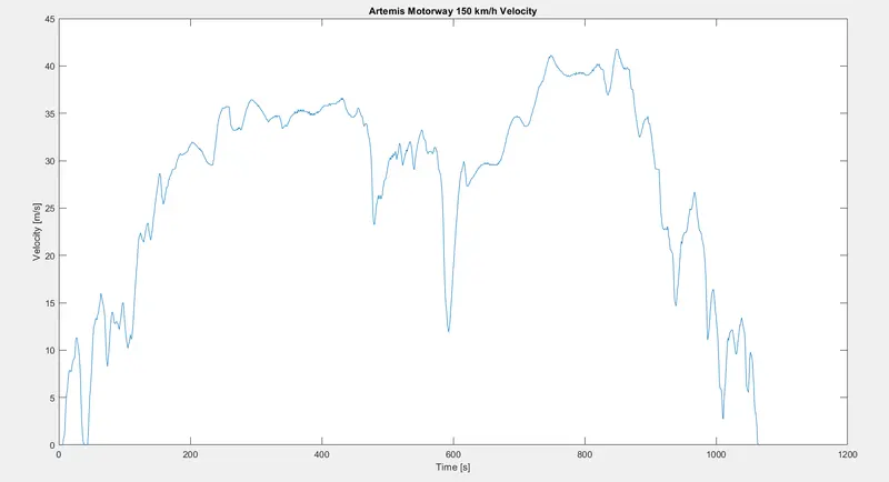
A drive cycle is a data set that contains velocity and time data for the purpose of modelling the motion of a vehicle.
Block parameters:
Artemis Motorway 150kmph Drive cycle graph is given as input to the vehicle model
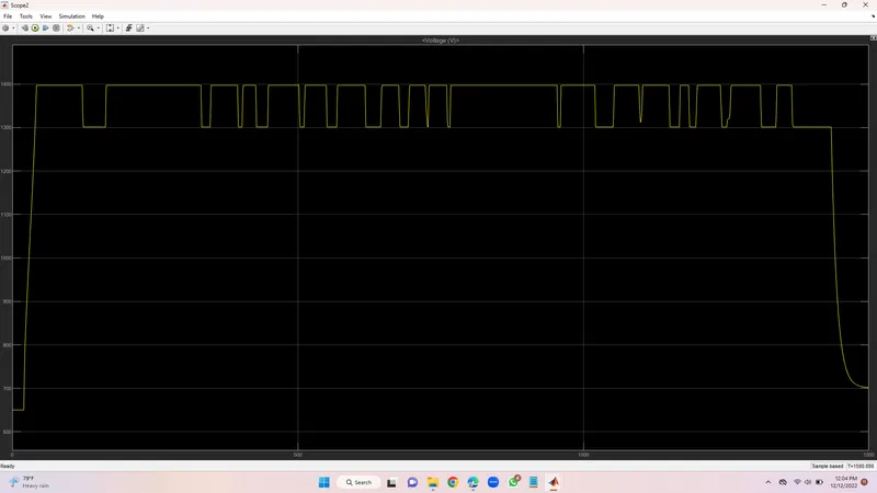
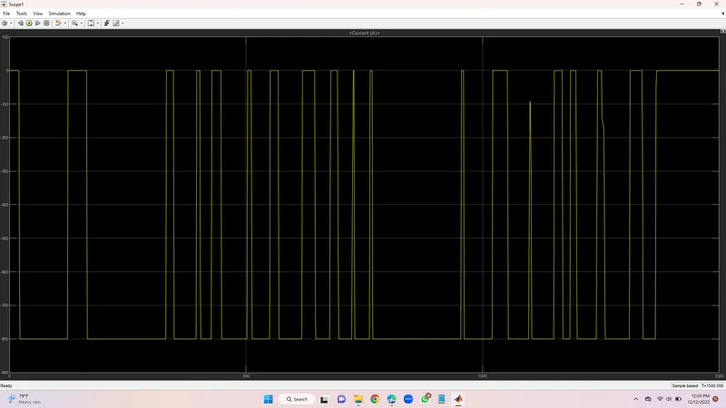
Results: Run the above drive cycle for EV model and took the outputs given from speed, current and SOC scopes. The distance travelled by the vehicle in the drive cycle is also measured using the display block. Before simulation the run time was updated according to the drive cycle time 1068secs.
Speed scope:
Current scope:
SOC scope:
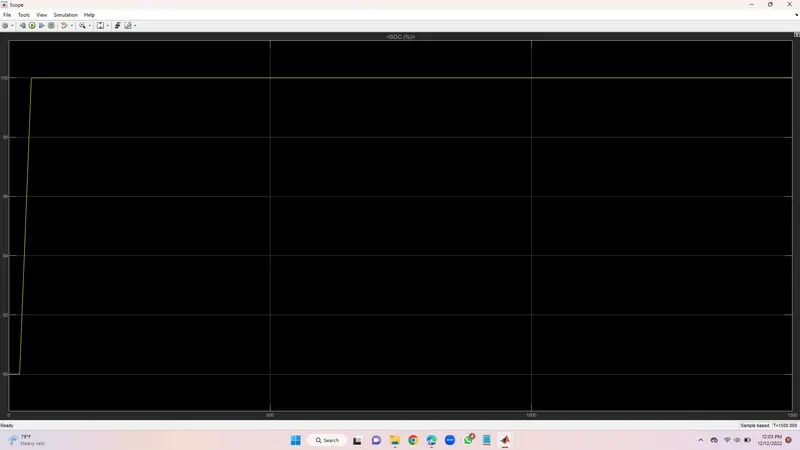
The SOC scope shows how the state of the battery varies over the drive cycle time, The batter was modelled to begin with an SOC pf 1 that is 100%. As the simulation starts the charge of the battery gets decreased and when the vehicle is in braking mode the uplift in the graph shows that regenerative braking is working to maintain the battery charge. After the whole simulation is over the State of charge percent lies at 75% after 1068 secs.
Distance travelled:
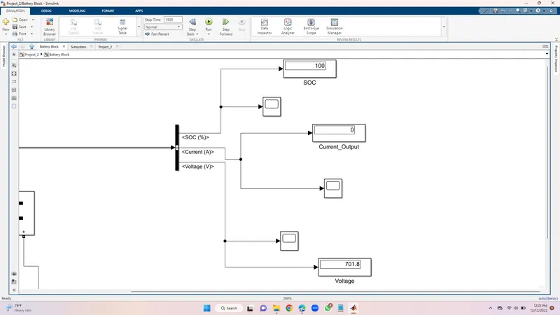
Vehicle travelled 3.182kms in 1500 secs and charge remaining 100%
Results:
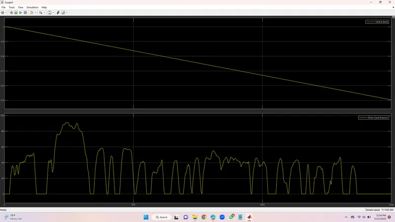
Vehicle travelled 3.182kms in 1500secs and charge remaining 100%
https://1drv.ms/w/s!Amvd91c_bnBlgSwLqFwz6p5E7LAb?e=sAQedU
D:\Introduction to Hybrid Electric Vehicle using MATLAB and Simulink\Project_2\Project_2.zip