Final Project: Design of an Electric Vehicle
Aim:
To developed the model for design of an electric vehicle
Objective:
Create a MATLAB model of electric car which uses a battery and a DC motor. Choose suitable blocks from Powertrain block set. Prepare a report about your model including following:
1. System level configurations
2. Model parameters
3. Results
4. Conclusion
Software usde:
MATLAB R2021-Simulink
Theory:
The Electric Vehicle model has divided into four major parts which include the primary components of the system. They are the Drive source, Motor and power controller, Battery system, and vehicle body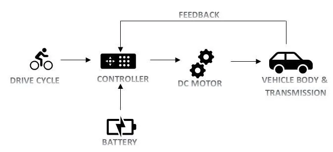
The prediction of performance and range of any vehicle is a very important concept for a designer which can be done easily by programming techniques using mathematics and spreadsheet programs such as MATLAB. These tools are an excellent basis for the simulation of an Electric vehicle and are much easier than other vehicles.
In order to determine the performance of an electric vehicle, the important parameter to be focused on is acceleration and top speed where the vehicles always have poor response. It is also mandatory for a designer to predict the range of a vehicle.
Now we see the simulation of the electric vehicle model to calculate the distance traveled by the vehicle for a given drive cycle by changing the parameters in Simulink and simscape blocks that are modeled using algorithms and some governing mathematical equations
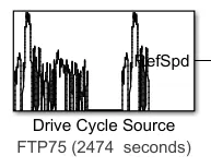
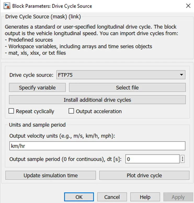
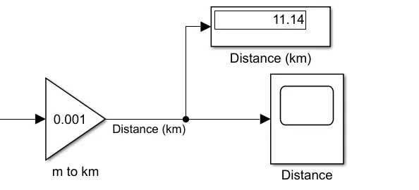
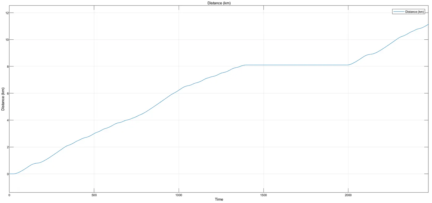
Drive cycle is the input data like how a human drive his actual vehicle here FTP75 drive cycle is introduced to to make the designed vehicle to give the output how it reacts to the drive cycle. The main object to design the EV is to obtain the speed by the driver, to estimate the state of charge (SOC), distance travelled by the vehicle. There is a SOC block that will estimate the state of charge of a battery, distance is calculated by speed and time parameters
MATLAB model:
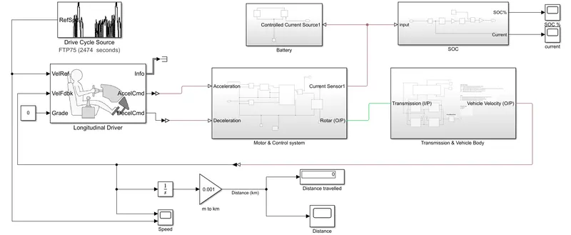
Initially the current flows the to DC Motor from the battery through the DC-DC power converter to drive the motor. The required voltage will controlled in the controller. The Controller will fallow the given drive cycle reference and run the motor in the required rpm. Then the motor power is transmitted to the wheels of a vehicle through the gear box. and the controller will take the vehicle speed and compair and controlled
Motor:
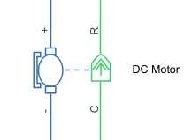
The motor converts electric energy into kinetic energy that moves the wheels. The advantage of using the motor instead of an engine is numerous: first, the noise and the vibration we typically associate with cars are minimized. Many passengers riding EVs for the first time are surprised by just how quiet and comfortable the ride feels. Moreover, the EV powertrain is smaller than the engine, thus providing lots of additional space for efficient vehicle design―like expanded cabin space
Battery:
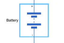
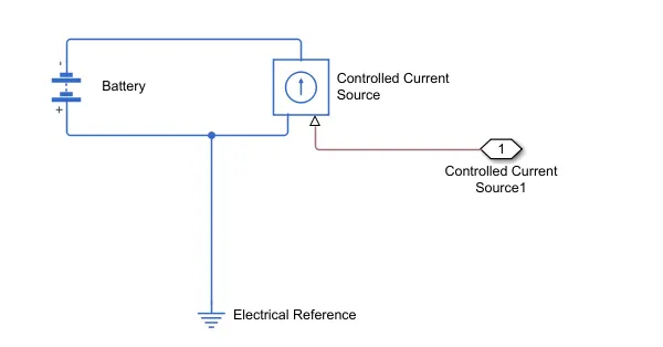
The battery stores electrical energy and is the equivalent of a fuel tank in an internal combustion engine. The maximum driving distance of an EV is often determined by the battery capacity―the higher the capacity, the higher the driving distance
where SOC is the state of charge and Vnom is the nominal voltage. Coefficient beta is calculated to satisfy a user-defined data point
Battery Management System(BMS):
The Battery Management System(BMS) manages the battery’s many cells so that they can operate as if they are a single entity. The EV’s battery consists of as little as tens to as many as thousands of mini-cells, and each cell needs to be in a similar condition to the others in order to optimize the battery’s durability and performance
Electric Power Control Unit(EPCU):
The Electric Power Control Unit(EPCU) is an efficient integration of nearly all devices that control the flow of the electric power in the vehicle. It consists of the inverter, the Low voltage DC-DC Converter(LDC), and the Vehicle Control Unit(VCU).
Inverter:
The inverter converts the battery’s DC into AC, which then is used to control the motor speed. The device is responsible for executing acceleration and deceleration, so it serves a crucial part in maximizing the EV’s drivability
Vehicle Control Unit:
As the control tower of all electric power control systems in the vehicle, The VCU is arguably the most important component of the EPCU. It oversees nearly all the vehicle’s power control mechanisms, including the motor control, regenerative braking control, A/C load management, and power supply for the electronic systems
State of charge:
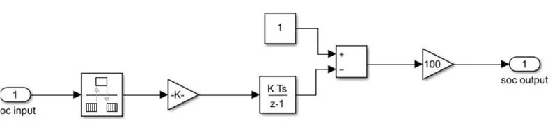
SOC is the percentage or level of battery presents after certain travel or consumption of battery charge by the vehicle. In the designed vehicle battery charge or SOC is calculated by the giving it to the rate transition and then to gain to a discrete-time integrator and it will get minus from the 1 as it is considered a 100% of battery and it is multiplied with 100 to get percentage of battery present and the entire system is shown below
Drive Cycle:
Drive cycle is assumed as the driver's input of a vehicle, it replaced how a driver will drive a vehicle. These drive cycles are standard drive cycle which is used to test the vehicle performances.drive cycle will have high speed, low speed, braking conditions in it
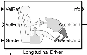
Driver Controller:
A parametric longitudinal speed tracking controller for generating normalized acceleration and braking commands based on reference and feedback velocities.
Use the external actions to input signals that can disable, hold, or override the closed-loop commands determined by the block. The block uses this priority for the input commands: disable, hold, override.
All the references are grounded. The positive and negative terminals are connected to the DC motor. Different parameters that are used for the simulation are shown below

Controlled PWM Voltage source:
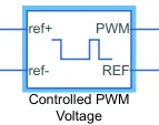
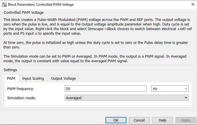
This block creates a Pulse-Width Modulated (PWM) voltage across the PWM and REF ports. The output voltage is zero when the pulse is low, and is equal to the Output voltage amplitude parameter when high.
Duty cycle is set by the input value. Right-click the block and select Simscape->Block choices to switch between electrical +ref/-ref ports and PS input u to specify the input value.
At time zero, the pulse is initialized as high unless the duty cycle is set to zero or the Pulse delay time is greater than zero
Power Converter:
H-Bridge:
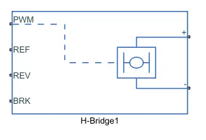
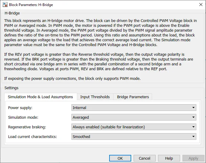
This block represents an H-bridge motor drive. The block can be driven by the Controlled PWM Voltage block in PWM or Averaged mode.
In PWM mode, the motor is powered if the PWM port voltage is above the Enable threshold voltage. In Averaged mode, the PWM port voltage divided by the PWM signal amplitude parameter defines the ratio of the on-time to the PWM period.
Using this ratio and assumptions about the load, the block applies an average voltage to the load that achieves the correct average load current
Vehicle Body & Transmission:
Motor will produce the rotational output which will give to the vehicle body and transmission system. The rotational output is taken by the gear system here to maintain the constant speed throughout the transmission without any loss in speed from the motor to tires. Below is a diagram that is how it is how it inside the vehicle body and transmission system and in the main design, it is referred just only as a transmission system.
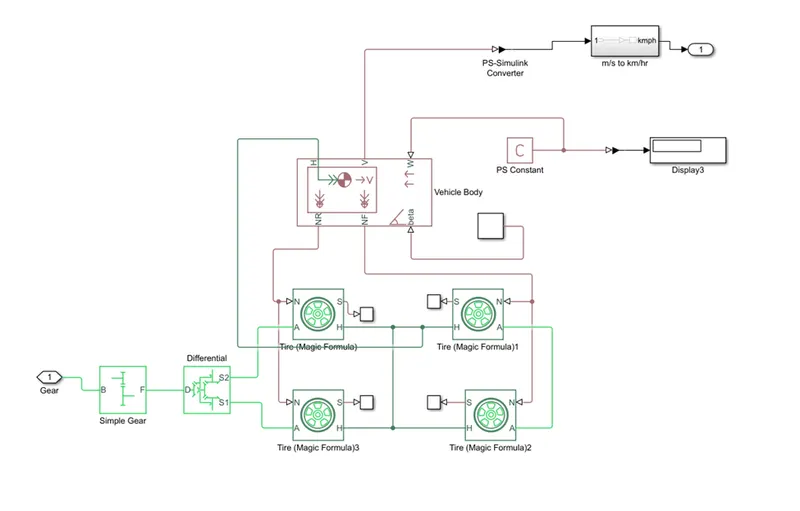
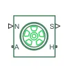
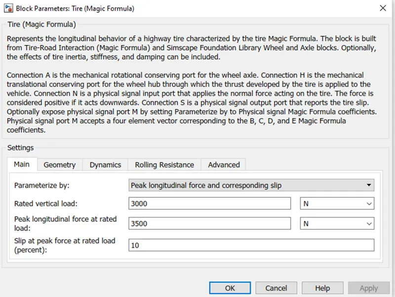
The gear output is given to axels of front tires, in the circute it is shown that gear is connected to front wheels and front tires are connected to rear tires, thus vehicle moves forward. N is the normal force caused by the tires and it is given to the vehicle body normal force port.
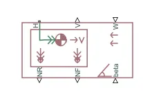
The vehicle body has an H-Hub, S- Tire slip, N- Normal force, A- axel connection, wind velocity, inclination angle. The tires hub is connected as a common node to the vehicle body. The vehicle body wind velocity is connected to a constant block and the beta-inclination angle is connected to another constsnt block where we can assign wind velocity and inclination angle as per requirement.
Velocity is the output port where we can get at which speed the vehicle is moving. The velocity is taken out to the get the distance travelled and stse of charge.
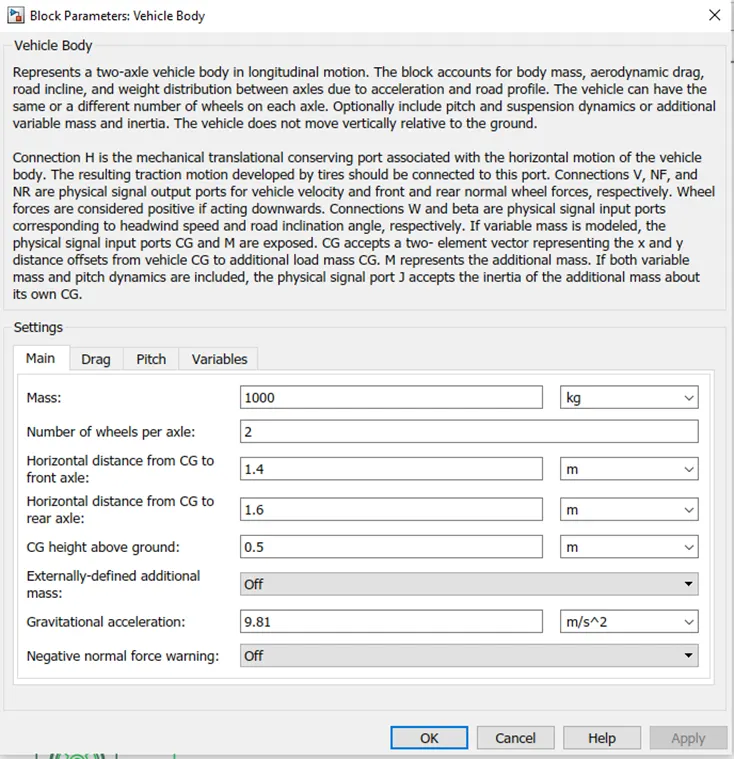
The frontal area and the drag coefficient should be kept as low as possible so that the power requirements to overcome the aerodynamic forces can be reduced. The mass of the vehicle also has effects on the vehicle performance, range, and cost of an electrical vehicle. It mainly affects the rolling resistance, power, and energy. when the vehicle climbs a hill, there will be kinetic energy loss occurs when the vehicle is accelerating and decelerating
Tire block:
Gear block:

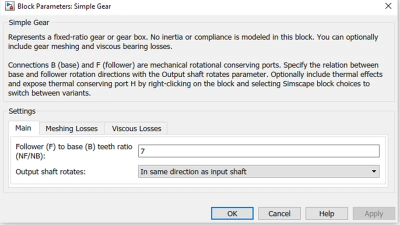
Here the Gear Ratio is changed to 7 to increase 7times the torque produced by the motor. This torque is provided to the rear axle of the vehicle to increase the propulsion. Electrical vehicles transmission is much simpler as the motor provides motion from zero speed upwardsi.e.by just connecting a simple gear ratio provided with differential.
Differential block:
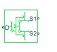
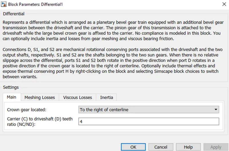
Default values of the block parameters are taken for simulation. The differential provides the tractive force equally to both rear and front wheels. But due to the space and power loss constraints, these differentials are eliminated. In this model, the differential is placed providing meshing, vicious and inertia losses are all zero. If the differential is removed, then a powerful electronic controller is needed to provide equalized torque to all the wheels.
Motor control system:
TheMotor controller will get input from the longitudinal driver. Its tasks are to control the speed of the motor and drive according to the input of the driver. Majorly motor controlled we designed had two main parts named PWM voltage generator and H-Bridge
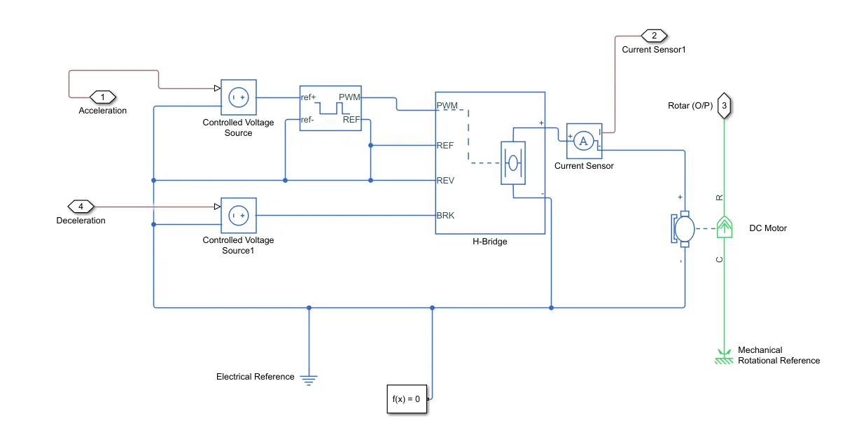
Input1 is getting from the accelmd of a longitudinal driver and it is given to a controlled voltage source block where it is input to the controlled PWM voltage. Controlled PWM voltage will generate a PWM signal in such a way that H-bridge will generate the required voltage to operate the DC motor for the given driver input. PWM voltage block negative reference and REF are grounded and REF of H-bridge respectively.
H-bridge is a motor controller that has IGBT components aligned in the shae of H and will operate only two at a time respectively to the input of the signal from the PWM block. When decelaration occur this H-bridge will give an output from the positive and negative terminals of it. These negative & positive terminals are later connected to the DC motor and battery.
All these components are the simscape electrical components so they need a connection to the solver configuration block which helps to solve the simulation
Result:
Distance traveling:
speed travelling:
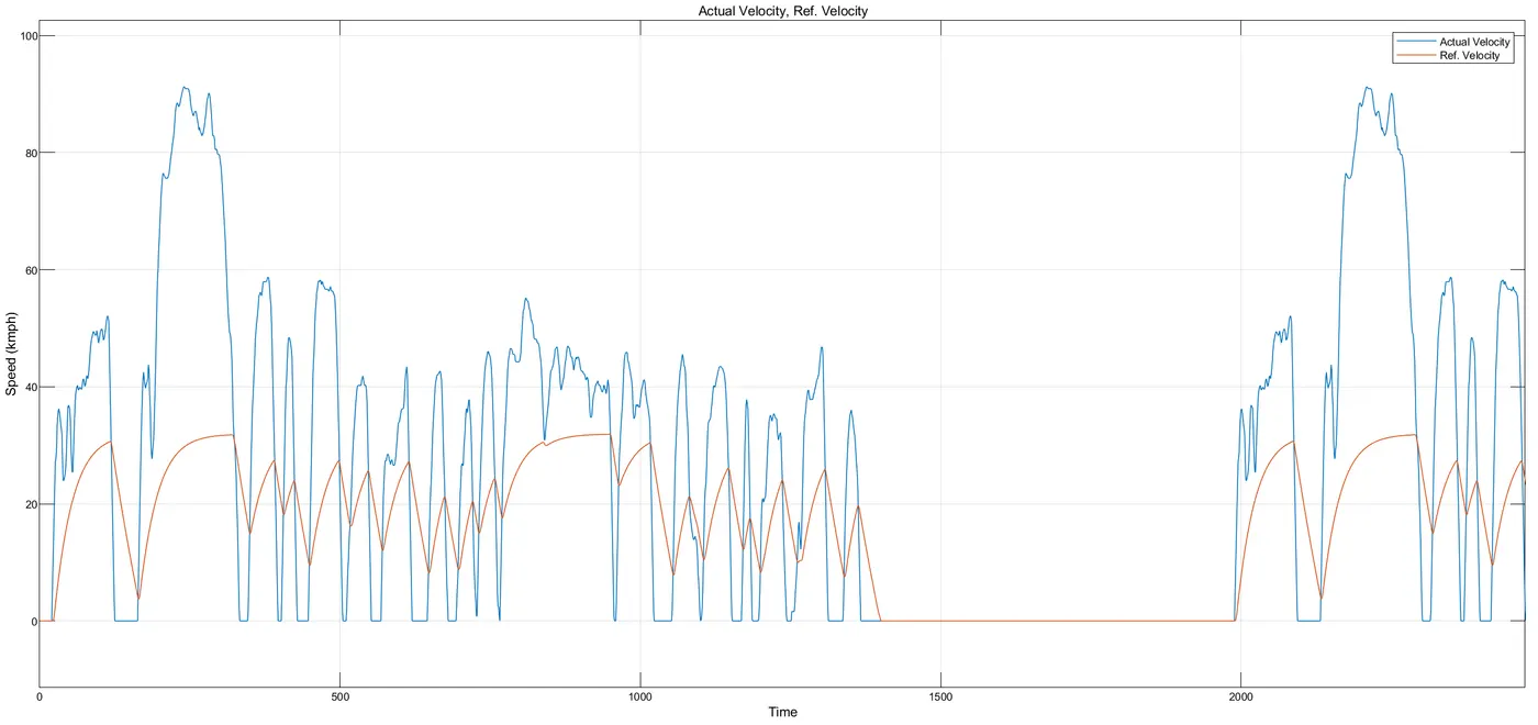
From the obtained vehicle speed performance we can conclude that vehicle has attend its maximum speed and there is a delay in the deceleration and the acceleration
SOC charge:
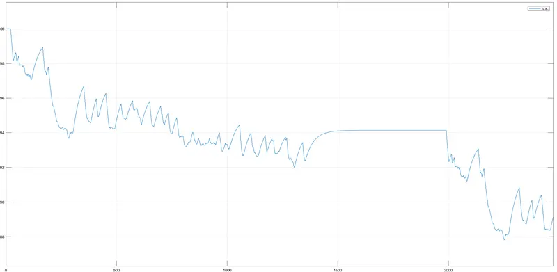
The SOC of the battery goes from 100% to around 88%. We can see from the curve the state of charge is decreased by some amount. In some instances this increased, that is representing the regenerative braking.
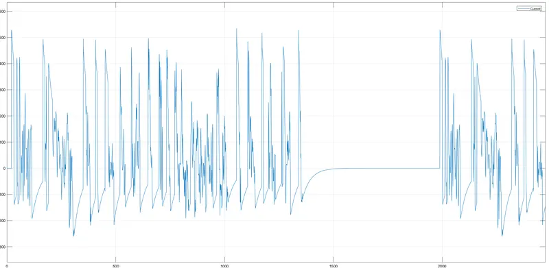
This curve for voltage is representative of the voltage that goes into the voltage. So, on comapringit with the drive cycle data, it can be said that when the velocity of the vehicle is increasing the motor consumes more amount of voltage and while deceleration the voltage consumption by the motor is less. Also, on comparing the velocity feedback, it is observed that the characteristics for them are same
Conclusion:
drive link;
https://drive.google.com/file/d/1AlZ7JfzZMYntHvJZ0MvvduqPGX8HbIAJ/view?usp=sharing