Final Project: Design of an Electric Vehicle
Create a MATLAB model of electric car which uses a battery and a DC motor. Choose suitable blocks from Powertrain block set. Prepare a report about your model including following:
Objectives:
1. System level configurations
2. Model parameters
3. Results
4. Conclusion
ANS:-
Sol: Here we are going to consider an EV model for an FTP75 drive cycle. The battery source is of 48V and the motor is DC type.
Block Diagram of EV model:
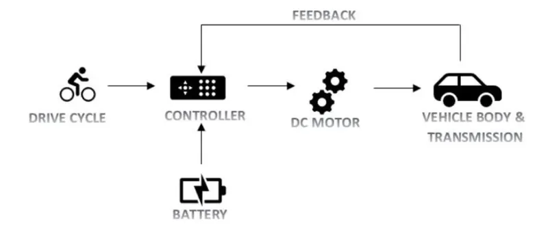
In the designed EV model, the main blocks are drive cycle, controller, DC motor, Vehicle body and Battery. Drive cycle is the driving pattern for which this model is going to be tested or evaluated. The main objective here is to obtain the speed attained by the driver, the SOC (state of charge), distance travelled by the vehicle.
The main Simulink model of the EV is as shown below:
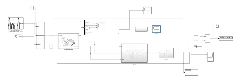
The Simulink model has been attached in the attachments.
Let us now discuss the various blocks in detail.
VEHICLE :
i) Vehicle Body Block:
In this model we have to first add the vehicle body block as shown below:
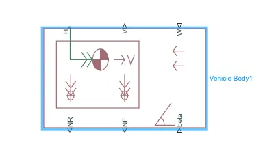
This block contains 6 ports which can be used to model the various aspects of the vehicle body. The ports are mentioned and elaborated below:
- H- This stands for ‘Hub’ and is used to connect the hubs of the wheels to the main body of the vehicle.
- V - This is a physical signal output port which stands for ‘Velocity’ and is used to output the speed/velocity at which the vehicle is moving at.
- W- This is a physical signal input port and allows us to model a ‘headwind' acting on the vehicle by giving a speed for it.
- NR - This is a physical signal output port to model the rear wheel normal forces.
- NF - This is a physical signal output to model the front wheel normal forces.
- beta - This is a physical signal input port and allows us to model the vehicle on an inclination angle to create the effect of a hill climbing force.
Now we need to define the vehicle body parameters as shown below:
For 'Main' Tab:
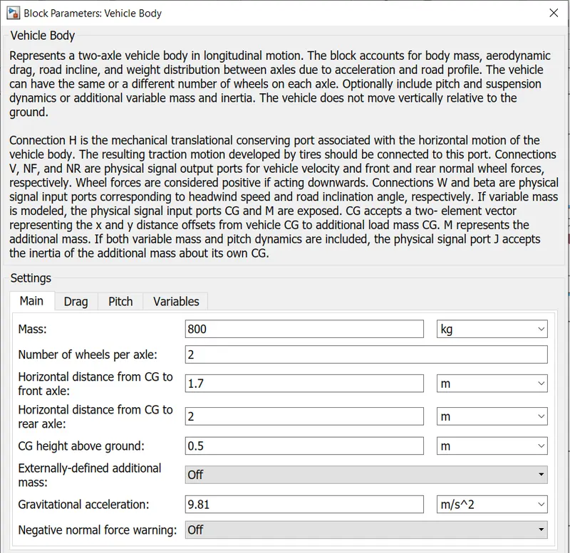
For 'Drag' Tab:
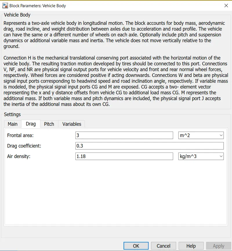
For 'Pitch' & 'Variables' Tab: Default values have been considered
ii) Tyres:
The tyres used in this EV model are 'magical formula' tyres. There are several tyre blocks that can be used for EV modelling but I have used the magical formula ones because it allows us to model the longitudinal behavior of tyres on highways. They also allow us to take into consideration extra effects such as tyre inertia, stiffness, etc which helps in better accuracy of real world conditions.
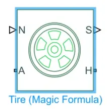
In the above image we can see that it has 4 ports and they are:
- N-This port stands for ‘Normal’ and is the physical signal input port for the normal force acting on the tire and is considered positive in the downwards direction.
- S-This port stands for ‘Slip’ and is the physical signal output port is that reports the slip acting on the tire.
- A- This port stands for ‘Axle’ and is the mechanical rotational conserving port for the wheel axle.
- H- This port stands for ‘Hub’ and is the mechanical translational conserving port for the wheel hub through which the thrust developed by the tires is applied to the vehicle body.
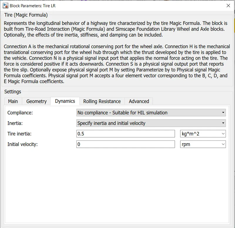
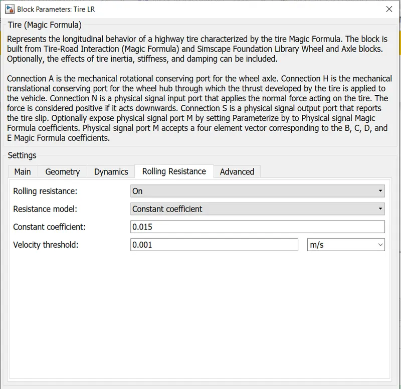
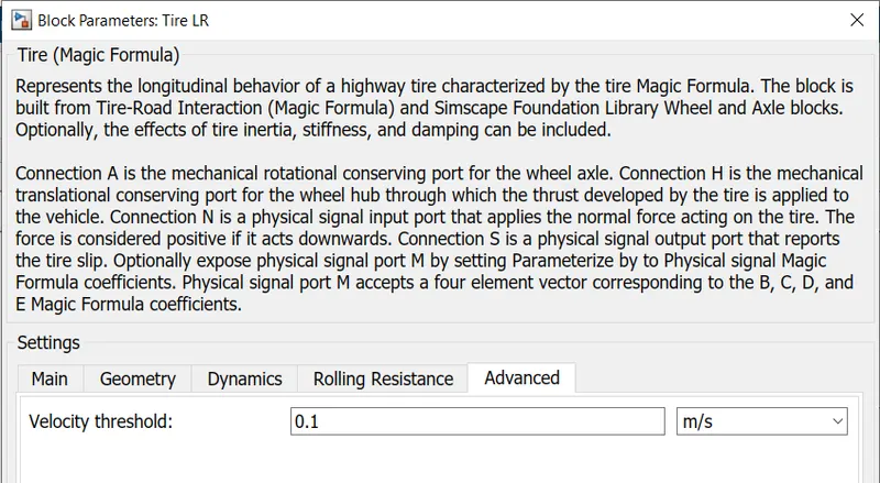
Now onto the Tyre Parameters, I have considered the following values:
For 'Main' Tab:
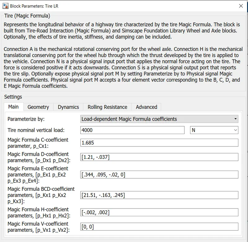
For 'Geometry' Tab:
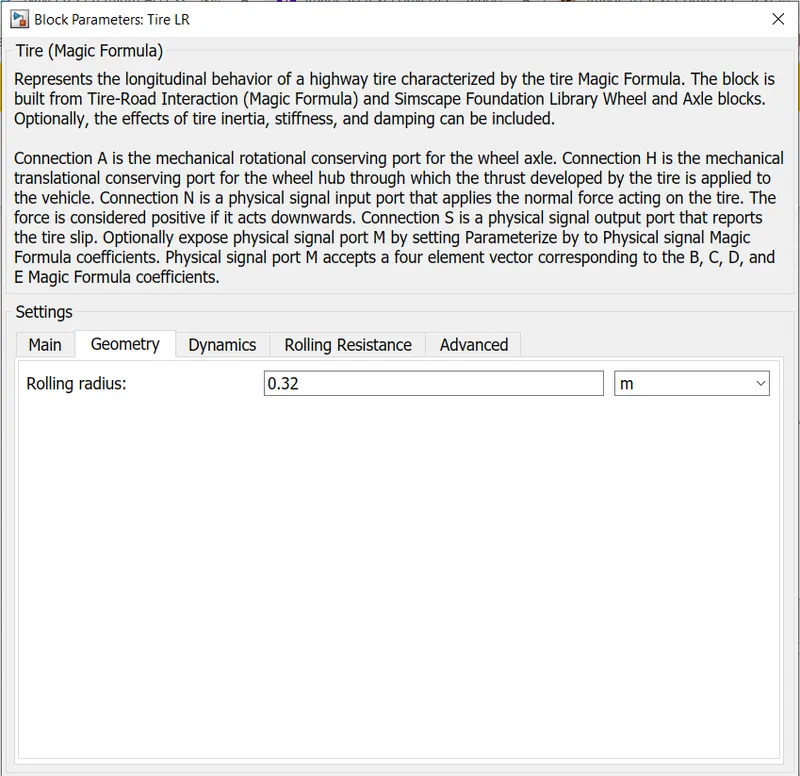
For 'Dynamics' Tab:
For 'Rolling Resistance' Tab:
For 'Advanced' Tab:
iii) Gear:
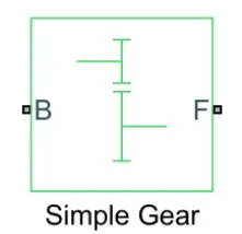
Here I have chosen 'Simple Gear' block as to simplify the transmission system parameters. This block models a gear system with a fixed gear ratio and with no inertia effects, however we can modify the effects of meshing of gear teeth. The simple gear block is as shown below:
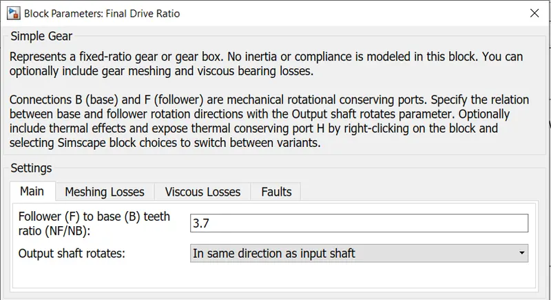
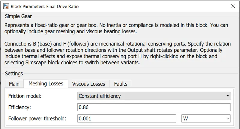
Now into the Simple Gear Parameters, I have considered the following values:
For 'Main' tab:
For 'Meshing Losses' Tab:
For 'Viscous Losses' & 'Faults' Tab : Default values considered.
iv) Side Shafts:
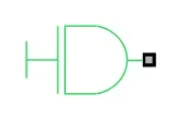
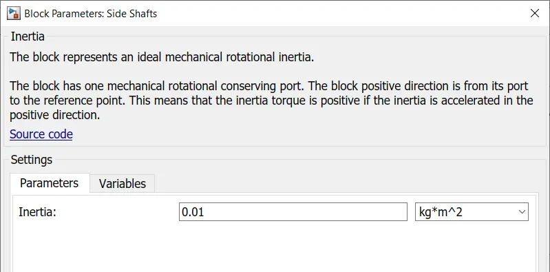
An inertia block has been added to the workspace to provide an ideal mechanical rotational inertia for the simple gear block. This block has only one mechanical rotational conserving port and the positive direction of the block is from the port to the reference point which would be the simple gear in this case. The inertia torque acts in the positive direction is the inertia is accelerated in the positive direction. The inertia block is shown below:
The inertia block parameters were set as below:
v) Wind and Slope:
Both wind & slope are considered as constant blocks and the parameters are as follows:
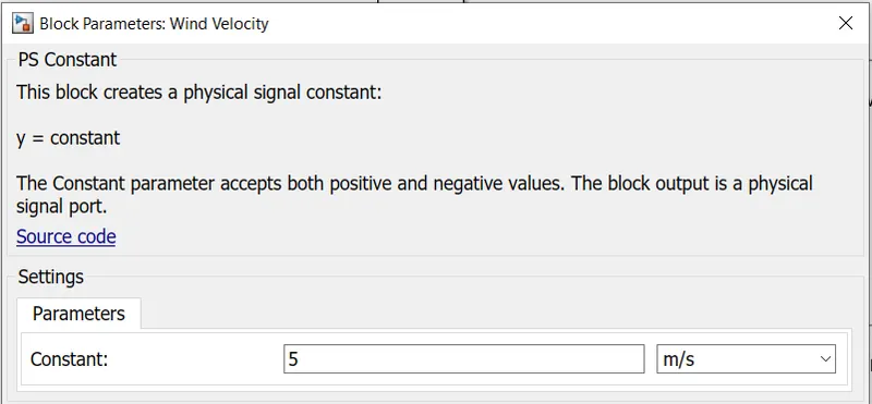
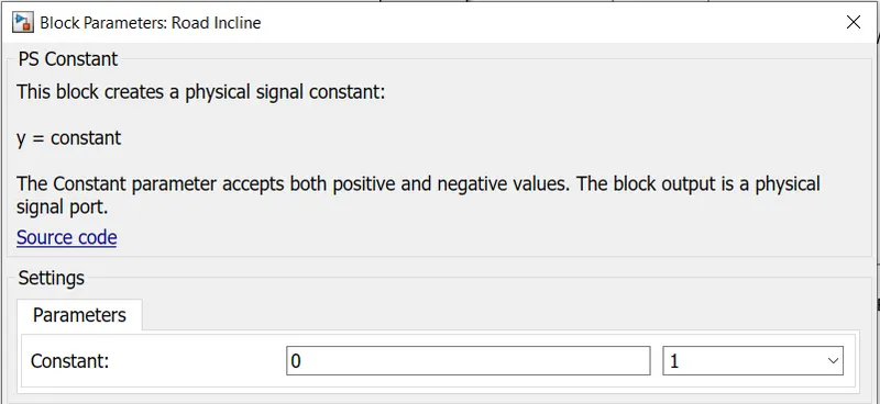
The following image represents the Vehicle Body block modelled in SIMULINK.

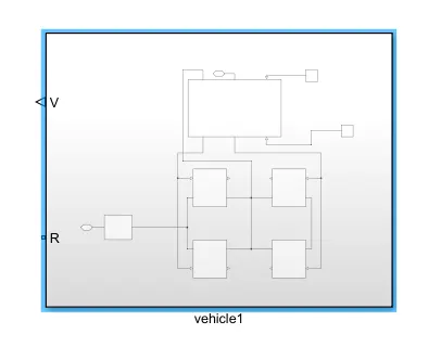
As seen in the diagram above, the various blocks are connected to model the vehicle body. 4 magic formula tire blocks are used as the vehicle will have 4 tires, 2 on each axle. The tires are LR, LF, RR and RF (left rear, left front, right rear, and right front). The normal ports of each tire are connected to the appropriate NR and NF ports on the vehicle body block. The hubs of each tire are connected together and an extra connection is made from them to the vehicle body block. The wind velocity and road incline are provided with constant physical signals of 5 m/s and 0 degrees respectively. The velocity port has been connected to the velocity subsystem and the connection from the subsystem is open to the 'v' port. The base port of the simple gear has been left open to the 'R’ port to take in a rotational signal. If all these connections are made, all of these components can be selected and made in to a subsystem shown below:
MOTOR:
For the EV model, I have chosen a DC Motor block as the motor. Below is the model of DC Motor:
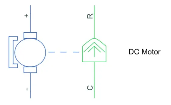
As we can see, there are 2 sides to the block: the mechanical side on the right and the electrical side on the left. The mechanical side has 2 ports, C and R. The C refers to the casing and the R for the rotation of the rotor which produces a torque. The electrical side has a positive and a negative terminal for the voltages to be applied. If a positive voltage is applied to the DC motor block from the positive to the negative terminal, a positive torque will act from the C port to the R port. The direction of the torque produced by the DC motor can be changed by changing the sign of the back emf or the torque constant. The C port of the mechanical side needs to be connected to a mechanical rotational reference because it will be stationary. The R port will be connected to the open connection of the simple gear from the vehicle body block. The positive terminal on the electrical side is connected to the positive terminal of a power converter which in my case will be an ‘H bridge’.
The mechanical rotational reference block is shown below:

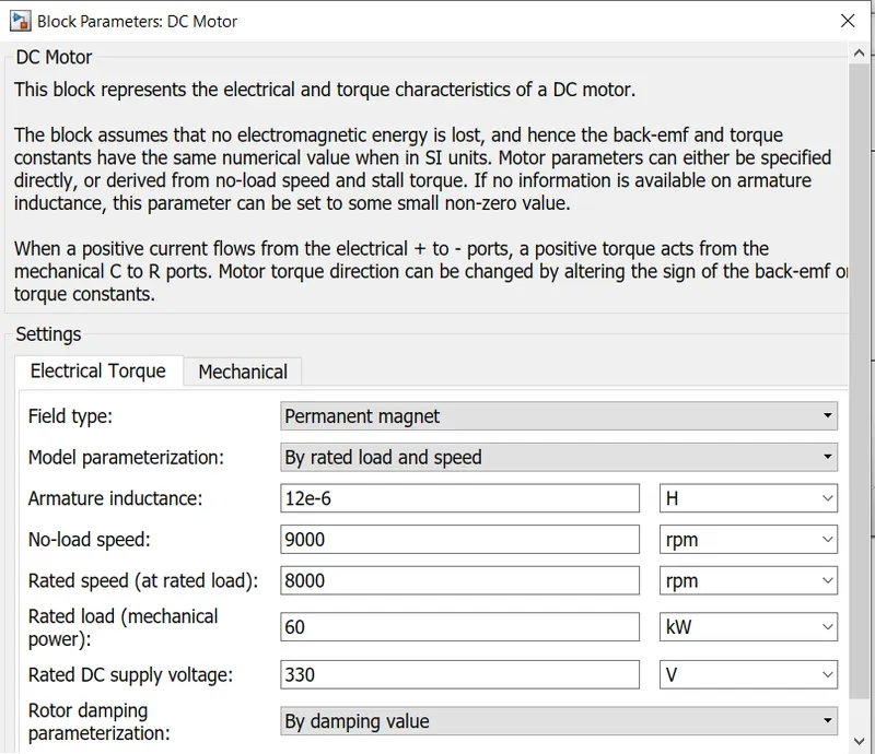
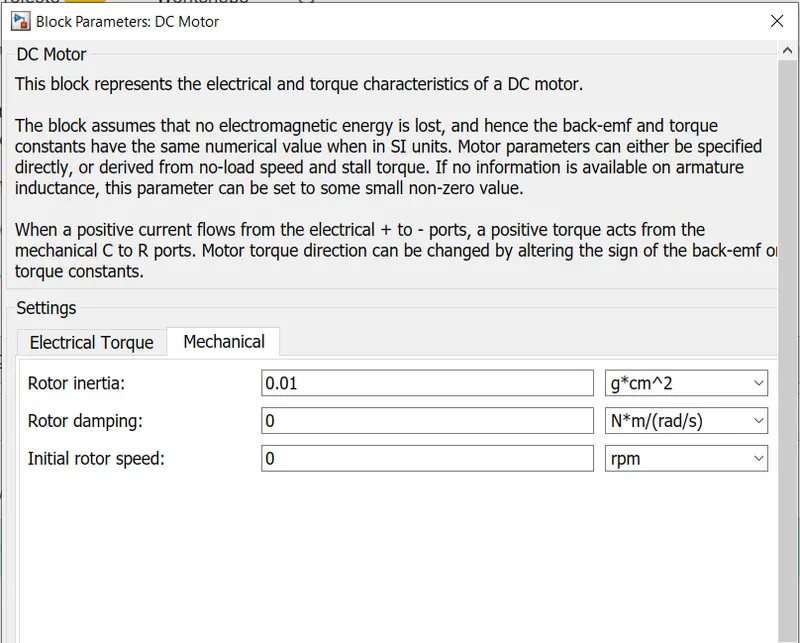
The DC Motor parameters which I have considered are as follows:
For 'Electrical Torque' Tab:
For 'Mechanical' Tab:
POWER CONVERTER:
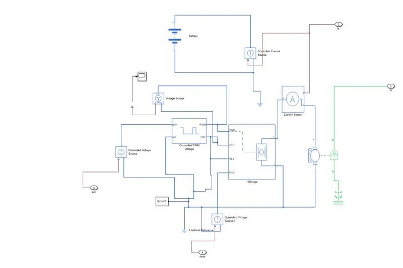
The power converter is needed to provide power of the correct form and magnitude from one component to another. In the case of EVs, a power converter is needed to provide a DC voltage from the battery of the EV to the DC motor so that it can operate properly with the required parameters. As mentioned earlier, I have used an H-Bridge motor drive as my power converter. Its block is shown below:
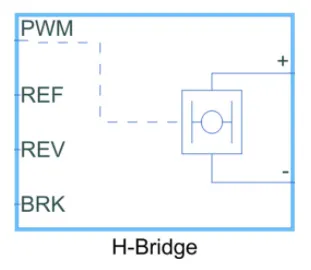
The H Bridge has 2 sides to it: the left side is for the controlling of the voltage signals and the right side is for the terminals to provide the controlled voltage to the DC motor. The left side ports of the H-Bridge block are:
- PWM - This stands for Pulse Width Modulation which will provide the voltage pulses to the H-Bridge either in the PWM or average mode.
- REF - This stands for Reference.
- REV - This stands for Reverse.
- BRK - This stands for Brake.
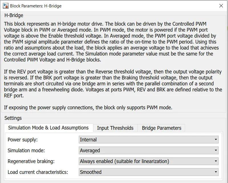
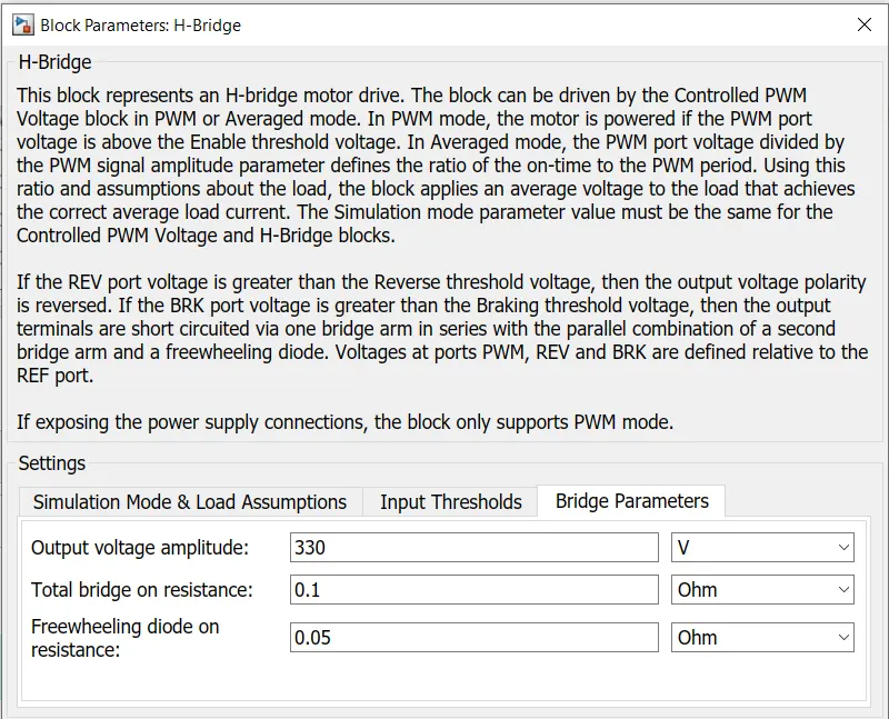
The parameters for H-bridge block I considered are as follows:
For ' Simulation Mode & load Assumptions' tab:
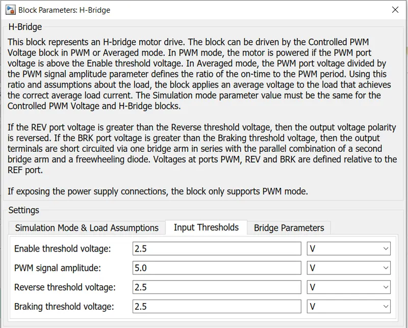
For 'Input Thresholds' Tab:
For 'Bridge Parameters' tab:
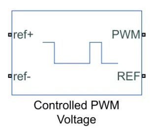
CONTROLLED PWM VOLTAGE BLOCK:
This block is used to provide a controlled pulse width modulated voltage to the H-bridge block.
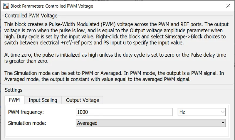
The parameters for this block were set as below:
CONTROLLED VOLTAGE SOURCE:
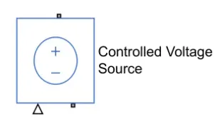
The input ports of the controlled PWM voltage block are still unconnected and that is because they require a controlled voltage source to provide the voltages to produce the voltage pulses to be fed in to the H-Bridge. For this, I have used the controlled voltage source block. This block is useful because it will provide the necessary voltage that is powerful enough to maintain the voltage at the output regardless of the current that passes through it. This controlled voltage source block is shown below:
ELECTRICAL REFERENCE:
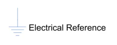
This block is used to create grounding effect for the electrical circuit. An electrical reference block is as shown below:
SOLVER CONFIGURATION:
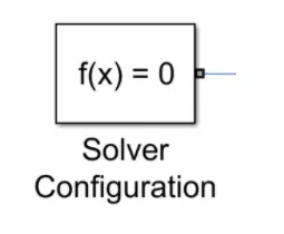
This block is used to solve necessary equations in any model.
the power converter blocks are as follows:
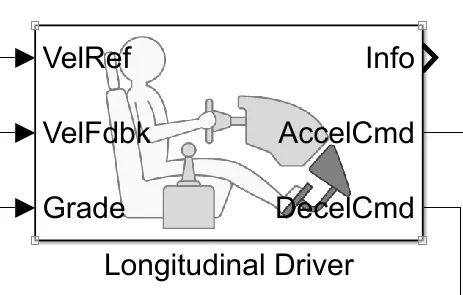
LONGITUDINAL DRIVER:
Below is the Longitudinal driver block:
DRIVE CYCLE:
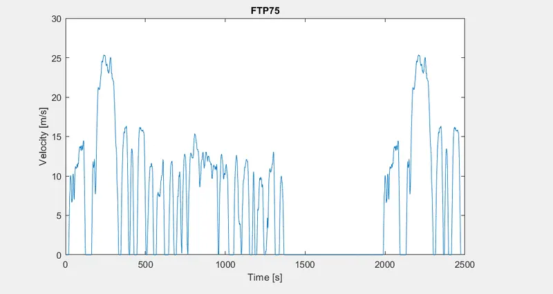
I have considered the FTP75 drive cycle and the output of this block is connected with 'Veh Ref' port of the longitudinal driver.
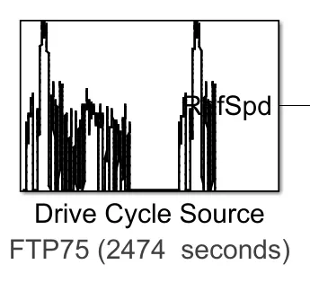
Please refer the attached simulink model or the EV model image for details regarding to the connections between longitudinal driver and other blocks.
BATTERY SYSTEM:
The battery block used is as shown below:
The parameters considered are as follows:
For 'Main' Tab:
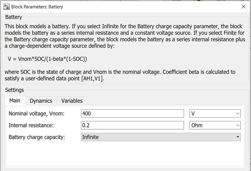
For 'Dynamics' & ' Variables' Tab: Default values considered.
CONTROLLED CURRENT SOURCE:
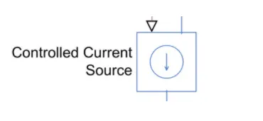
The controlled current source block is a part of the battery system used in the EV model. Similar to the controlled voltage source, this block will represent an ideal current source that is powerful enough to maintain the specified current regardless of the voltage across it. The controlled current source block is shown below:
CURRENT SENSOR:
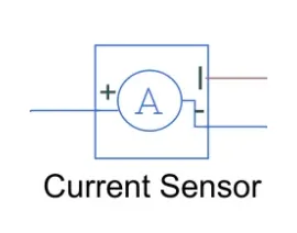
The current sensor block represents an ideal current sensor and is used to convert the current measured in an electrical circuit to a physical signal that is proportional to the current. This block is used to measure the current between the battery circuit (controlled current source) and the DC motor. The current sensor block is shown below:
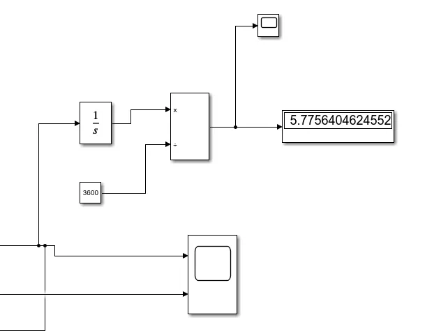
The following blocks are used to calculate the speed and the distance travelled by the vehicle:
RESULTS:
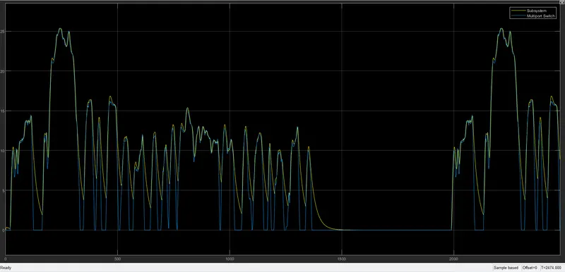
1) SPEED SCOPE:
2) CURRENT:
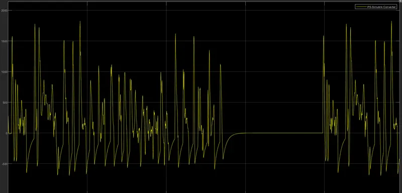
3) SOC:
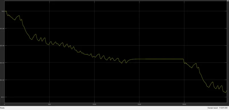
CONCLUSION:
In conclusion, the EV model has been created with the necessary block components using the SIMULINK software and the model has been simulated for a customized FTP75 drive cycle. The simulation has produced results of the velocity of the vehicle, current flowing from the battery, and the SOC of the battery as well as the distance travelled by the EV. Since the EV model was parameterized to simulate averaged voltage pulses in the H-Bridge and Controlled PWM voltage blocks to be fed in to the DC motor, the simulation finished very quickly within a matter of seconds. The EV model was able to follow the commands given by the reference velocities from the drive cycle data,
although it could have followed the reference signals more closely.
I have attached the EV model with the attachments.