Final Project: Design of an Electric Vehicle
Create a MATLAB model of electric car which uses a battery and a DC motor. Choose suitable blocks from Powertrain block set. Prepare a report about your model including following:
Objectives:
1. System level configurations
2. Model parameters
3. Results
4. Conclusion
Electric Vehicle –
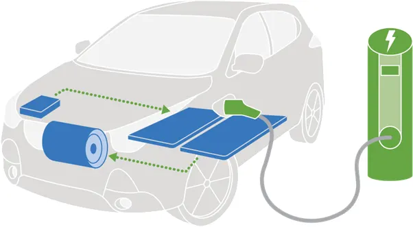
All-electric vehicles, also referred to as battery electric vehicles (BEVs), have an electric motor instead of an internal combustion engine. The vehicle uses a large traction battery pack to power the electric motor and must be plugged in to a wall outlet or charging equipment, also called electric vehicle supply equipment (EVSE). Because it runs on electricity, the vehicle emits no exhaust from a tailpipe and does not contain the typical liquid fuel components, such as a fuel pump, fuel line, or fuel tank
An electric vehicle (EV) is one that operates on an electric motor, instead of an internal-combustion engine that generates power by burning a mix of fuel and gases. Therefore, such as vehicle is seen as a possible replacement for current-generation automobile, in order to address the issue of rising pollution, global warming, depleting natural resources, etc. Though the concept of electric vehicles has been around for a long time, it has drawn a considerable amount of interest in the past decade amid a rising carbon footprint and other environmental impacts of fuel-based vehicles.
EVs have an electric motor instead of an internal combustion engine (ICE). The vehicle uses a large traction battery pack to power the motor and must be plugged in to a charging station or wall outlet to charge. Most EVs use lithium-ion batteries, which have higher energy density, longer life span and higher power than most other practical batteries.
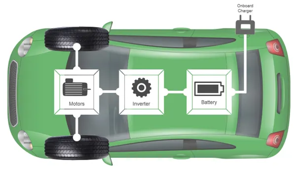
An electric vehicle(EV) is defined as a vehicle that uses an electric motor or a traction motor for propulsion instead of internal combustion used by conventional vehicles. Electric vehicle use electricity for power instead of fossil fuels like conventional vehicles . So, they do not produce any exhaust gases and pollution. The power needed in the EV come from batteries, generator or any collector system. Batteries fitted in the EV are of high energy densities in order meet the power requirements and range.
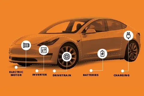
The inner parts of an EV –
1 - Electric Engine/Motor - Provides power to rotate the wheels. It can be DC/AC type, however, AC motors are more common.
2 - Inverter - Converts the electric current in the form of Direct Current (DC) into Alternating Current (AC)
3 - Drivetrain - EVs have a single-speed transmission which sends power from the motor to the wheels.
4 - Batteries - Store the electricity required to run an EV. The higher the kW of the battery, the higher the range.
5 - Charging - Plug into an outlet or EV charging point to charge your battery
Simple block diagram electric vehicle -
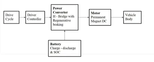
Modelling of EV Cars-
COMPONENTS:
The main components of the EV are –
1 Tire –
Tire is main part of vehicle when we are going through the design of EV car are required in tire and assemble .
The tire parameter are set –
Represents the longitudinal behavior of a highway tire characterized by the tire Magic Formula.
The block is built from Tire-Road Interaction (Magic Formula) and Simscape Foundation Library Wheel and Axle blocks. Optionally, the effects of tire inertia, stiffness, and damping can be included.
Connection A is the mechanical rotational conserving port for the wheel axle. Connection H is the mechanical translational conserving port for the wheel hub through which the thrust developed by the tire is applied to the vehicle.
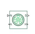
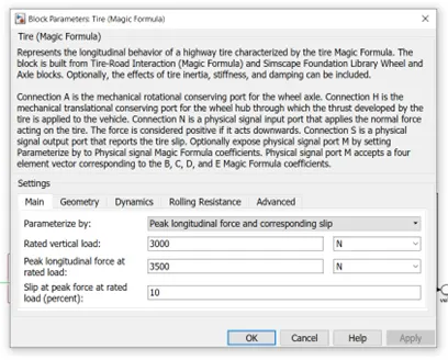
Design the EV cars so we are using in four tire .
2 Vehicle body –
When design the EV car are required the 4 tire and Vehicle body
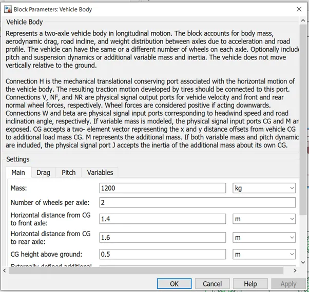
The Vehicle Body block represents a two-axle vehicle body in longitudinal motion. The vehicle can have the same or a different number of wheels on each axle. For example, two wheels on the front axle and one wheel on the rear axle. The vehicle wheels are assumed identical in size. The vehicle can also have a center of gravity (CG) that is at or below the plane of travel.
The block accounts for body mass, aerodynamic drag, road incline, and weight distribution between axles due to acceleration and road profile. Optionally include pitch and suspension dynamics. The vehicle does not move vertically relative to the ground.
The block has an option to include an externally-defined mass and an externally-defined inertia. The mass, inertia, and center of gravity of the vehicle body can vary over the course of simulation in response to system changes.
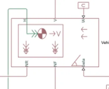
Represents a two-axle vehicle body in longitudinal motion. The block accounts for body mass, aerodynamic drag, road incline, and weight distribution between axles due to acceleration and road profile.
The vehicle can have the same or a different number of wheels on each axle. Optionally include pitch and suspension dynamics or additional variable mass and inertia.
The vehicle does not move vertically relative to the ground.
3 Gear Box –
The gear box is one of the most part of an vehicle in this case we are using in simple gear box in matlab
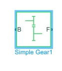
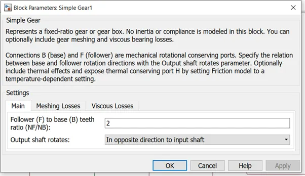
Represents a fixed-ratio gear or gear box. No inertia or compliance is modeled in this block. You can optionally include gear meshing, backlash, and viscous bearing losses.
Connections B (base) and F (follower) are mechanical rotational conserving ports. Specify the relation between base and follower rotation directions with the Output shaft rotates parameter.
Using the tire , vehicle body and simple gear box developing the vehicle body system
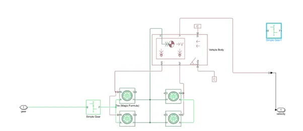
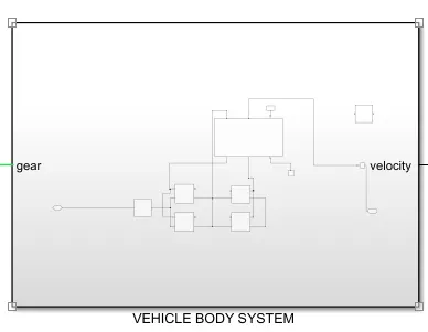
Every vehicle are consist of body , gear and tire assembly so develop the vehicle body system .
4 DC Motor –
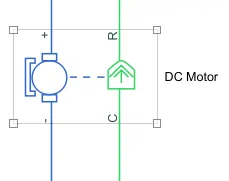
Motor is convert the electrical energy to mechanical energy in the EV car are Motor is main roll to drive the wheel in the car so using the dc motor with PWM motor .
In this example, you model a DC motor driven by a constant input signal that approximates a pulse-width modulated signal and look at the current and rotational motion at the motor output.
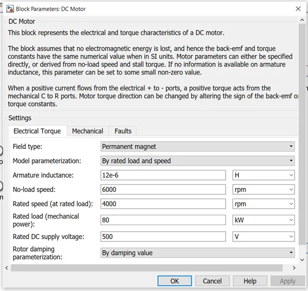
This block are Ve+ terminal are connected in converter + ve term and – ve of motor it is a connect – ve of converter .
5 H Bridge –
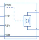
This is a power converter which is needed to provide power of the correct form and magnitude from one component to other. In case of EV,s a power converter is needed to provide a DC voltage from the battery of the EV to the DC motor, so that it can fuction properly at the required parameters.Here i have used an H-bridge motor drive as my power converter.
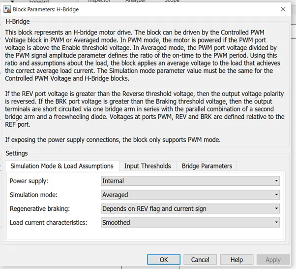
The H-Bridge block represents an H-bridge motor driver. The block has the following two Simulation mode options -
PWM — The H-Bridge block output is a controlled voltage that depends on the input signal at the PWM port. If the input signal has a value greater than the Enable threshold voltage parameter value, the H-Bridge block output is on and has a value equal to the value of the Output voltage amplitude parameter. If it has a value less than the Enable threshold voltage parameter value, the block maintains the load circuit using one of the following three Freewheeling mode options -
1- Via one semiconductor switch and one freewheeling diode
2- Via two freewheeling diodes
3- Via two semiconductor switches and one freewheeling diode
6 Controlled PWM Voltage source –
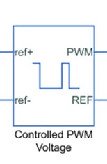
The Controlled PWM Voltage block represents a pulse-width modulated (PWM) voltage source. You can model electrical or physical signal input ports by setting the Modeling option parameter to either -
Electrical input ports — The block calculates the duty cycle based on the reference voltage across its ref+ and ref- ports. This option is the default.
PS input — Specify the duty cycle value directly by using an input physical signal port.
If you set Modeling option to Electrical input ports, the demanded duty cycle is
100∗Vref−Vmin * Vmax−Vmin percent
Where -
Vref is the reference voltage across the ref+ and ref- ports.
Vmin is the minimum reference voltage.
Vmax is the maximum reference voltage.
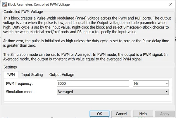
The value of the Output voltage amplitude parameter determines amplitude of the output voltage.
At time zero, the pulse is initialized as high, unless the Pulse delay time parameter is greater than zero, or the demanded duty cycle is zero.
A 'controlled PWM voltage' to provide a controlled pulse width modulated voltage to the H-bridge block. The pulses of voltage created by this block are dependent on the duty cycle which is in that ratio of the time that the switch is ON to the time taken for one cycle. The duty cycle formula is given by:- Duty cycle= Ton/Ton +Toff= Ton /Tcyc. where Ton = On time,Tcyc=Time taken for one cycle.
7 Controlled Voltage source –
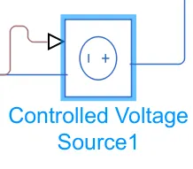
The Controlled Voltage Source block converts a Simulink® input signal into an equivalent voltage source. The generated voltage is driven by the input signal of the block.
You can initialize the Controlled Voltage Source block with a specific AC or DC voltage. If you want to start the simulation in steady state, the Simulink input must be connected to a signal that begins the simulation as a sinusoidal or DC waveform that corresponds to the initial values.
This block provides the necessary voltage that is powerfull enough to maintaion thr voltage at the output regardless of the current that passes through it.In this subsystem control voltage blocks ahve been used . One block is used for acceleration and other to provide the voltage for deacceleration.
8 Current Sensor –
The Current Sensor block represents an ideal current sensor, that is, a device that converts current measured in any electrical branch into a physical signal proportional to the current.
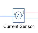
measures the current in the battery circuit and the DC motor. The positive and negetive terminals across which thecurrent sensor is inserted in to the circuit. The third port outputs the physical signal , In my model it sends the signal to te controlled current source.
9 Solver Configuration –
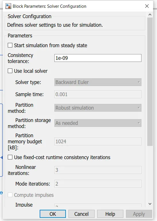
Each physical network represented by a connected Simscape™ block diagram requires solver settings information for simulation. The Solver Configuration block specifies the solver parameters that your model needs before you can begin simulation.
Each topologically distinct Simscape block diagram requires exactly one Solver Configuration block to be connected to it.
10 Electrical Reference –

The Electrical Reference block represents an electrical ground. Electrical conserving ports of all the blocks that are directly connected to ground must be connected to an Electrical Reference block. A model with electrical elements must contain at least one Electrical Reference block. The block has one electrical conserving port.
11 Mechanical Rotational Reference –

The Mechanical Rotational Reference block represents a reference point, or frame, for all mechanical rotational ports. All rotational ports that are rigidly clamped to the frame (ground) must be connected to a Mechanical Rotational Reference block.
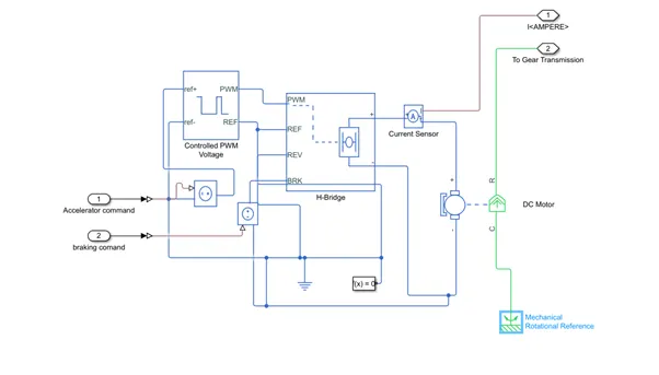
Using the DC motor , H Bridge ,Controlled PWM Voltage , Controlled voltage source , solver configuration , Electric and mechanical reference develop Motor and controller model
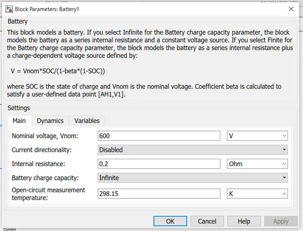
12 Battery –
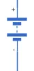
This battery block represents a simple battery model. The block models the battery as a series internal resistance and a constant voltage source.
The block and its parameters are shown below,
13 SOC (state of charge) estimate subsystem –
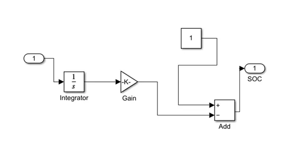
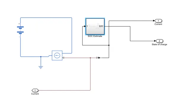
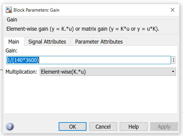
To measure the state of charge of the battery, a sub-system was created of various blocks. The first block is integrator block used to handle data transfer and integrate the value of the current signal with respect to time and next is the Gain block is used in order to multiplyer divide the signal coming from integrator block. This block will divide the current signal with the ampere ratingof battery which is 140(Ah)*3600(secs in hour) . Assuming the battery is always fully charged I have added the constant block with a value of 1 representing 100%.Next a sum block is used to perform addition and substraction operations athese blocks aremade into a subsystem called SOC estimate. A scope block is used at the junction of the PS-simulink converter block to plot the output signall of the current from the battery.
Using the battery and soc estimate block are develop battery subsystem –
Gain –
The Gain block multiplies the input by a constant value (gain). The input and the gain can each be a scalar, vector, or matrix.
You specify the value of gain in the Gain parameter. The Multiplication parameter lets you specify element-wise or matrix multiplication
Drive cycle -
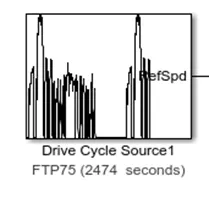
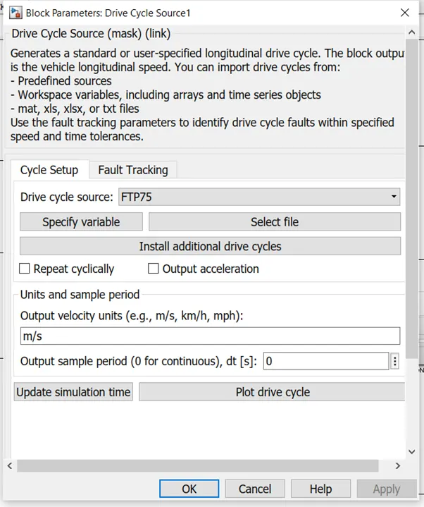
The Drive Cycle Source block generates a standard or user-specified longitudinal drive cycle. The block output is the specified vehicle longitudinal speed, which you can use to:
Predict the engine torque and fuel consumption that a vehicle requires to achieve desired speed and acceleration for a given gear shift reference.
Produce realistic velocity and shift references for closed loop acceleration and braking commands for vehicle control and plant models.
Study, tune, and optimize vehicle control, system performance, and system robustness over multiple drive cycles.
Identify the faults within tolerances specified by standardized tests, including:
EPA dynamometer driving schedules1
Worldwide Harmonised Light Vehicle Test Procedure (WLTP) laboratory tests2
For the drive cycles, you can use –
Drive cycles from predefined sources. By default, the block includes the FTP–75 drive cycle. To install additional drive cycles from a support package, see Install Drive Cycle Data. The support package has drive cycles that include the gear shift schedules, for example JC08 and CUEDC.
Workspace variables that define your own drive cycles.
.mat, .xls, .xlsx, or .txt files.
Wide open throttle (WOT) parameters, including initial and nominal reference speed, deceleration start time, and final reference speed.
We are using the block to given the input the driver with multiple switch to select different input to excl file is can be uploaded from spradsheet .
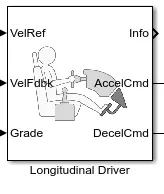
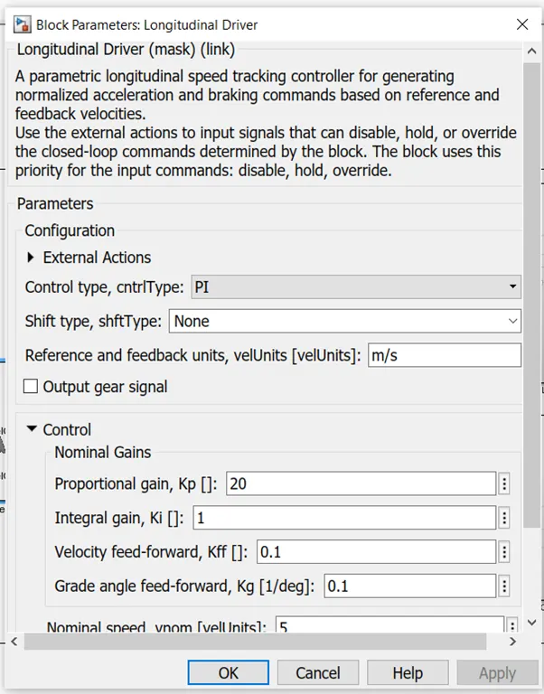
Longitudinal Driver –
The Longitudinal Driver block implements a longitudinal speed-tracking controller. Based on reference and feedback velocities, the block generates normalized acceleration and braking commands that can vary from 0 through 1. You can use the block to model the dynamic response of a driver or to generate the commands necessary to track a longitudinal drive cycle.
This is block are provide control signal or control the vehicle drive as control .
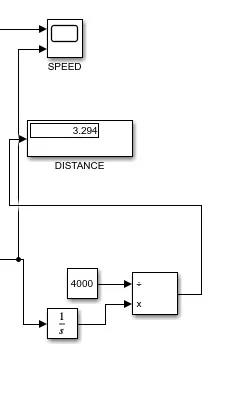
Traveling Distance measurement –
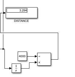
The below model are to be use in to find of distance travel . distance travel are use full to find the travel distance capacity as per selected battery pack how to overcome and improvement of given Ev model its helpfully to analysis of vehicle performance .
Developed model of EV Cars –
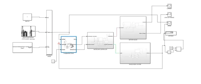
The EV vehicle are develop Motor and control system , Vehicle and their tire arrangement , Battery system ans State of charge system , driver control to use longitundel driver block , Drive cycle this block arrangement to develop the EV car
Results –
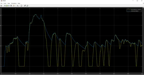
1 Speed –
After run the given ev model vehicle performance and speed in speed scope it is shown affect of speed change in vehicle . my EV model and took the outputs given from speed, surrent and SOC scopes .
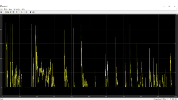
2 Current –
This scope are represent current stage at every time . Its represent the changing the speed is effected in battery current also represent the SOC effect and also show the current flow through the motor and battery
3 State of charge scope –
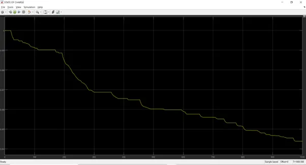
The SOC scope shows how the state of the battery varies over the drive cycle time, The batter was modelled to begin with an SOC pf 1 that is 100%. As the simulation starts the charge of the bettery gets decreased and when the vehicle is in braking mode the uplift in the grapf shows that regenerative braking is working to maintain the battery charge.
SOC Scope tells us the Variation in SOC and at what Discharge Rate our Battery is Depleting.
The last result displays the distance covered by the vehicle in Km. It is calculated by integrating the velocity feedback value .
Conclusion –
The advancing technology, it has taken a drift in the automobile industry with the introduction of Electric Vehicles. Electric Vehicles provide to humanity as a sustainable mode of transport, by not deteriorating the environment. This paper describes the procedure for modeling of an Electric Vehicle in MATLAB and Simulink, by explaining various- Motor Model, Battery Model, Power Model, and Regenerative System. Through Simulink, the designed Electric Vehicle is simulated and various factors like- Motor Torque, Vehicle Speed, State of Charge of Battery were calculated by providing Driving Cycle. The various observed factors were analysed for improving the model.
links -
https://drive.google.com/drive/folders/1kaTt0RvOsqSUSGDtsCRAWilTEYDxtz54?usp=sharing