Final Project: Design of an Electric Vehicle
Create a MATLAB model of electric car which uses a battery and a DC motor. Choose suitable blocks from Powertrain block set. Prepare a report about your model including following:
Objectives:
- System level configurations
- Model parameters
- Results
- Conclusion
Theory:-
An Electric vehicle is a veicle that uses one or more electric motors or traction motors for propulsion. An electric vehicle may be powered through a collector system by electricity from off-vehicle sources,or may be self-controlled with a battery,fuel cells or an electric generator to convert fuel to electricity.Evs include,but are not limited to,road and rail vehicles,surface and under water vessels,electric aircraft and electric space aircraft.
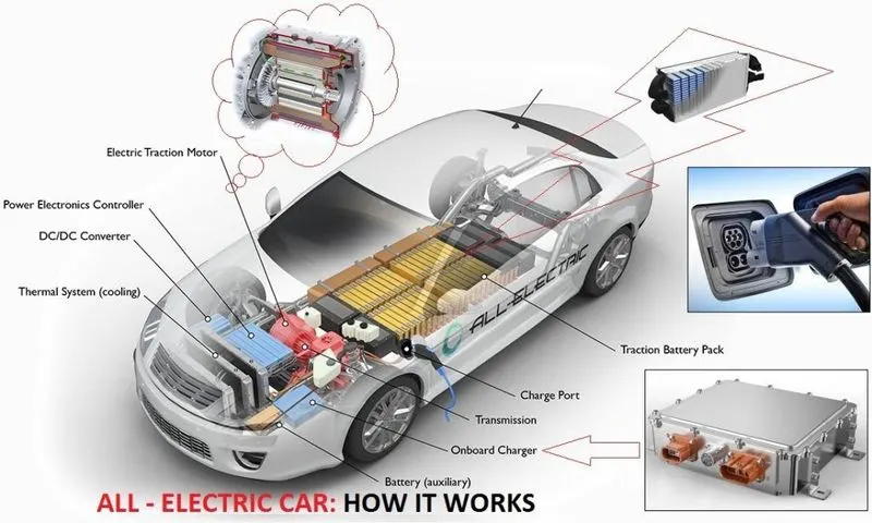
Components of EV:-
EV has no need for the fuel engine and gear transmission,the two of the most crucial components for internal combustion vehicles. an electric powered car has three primary components-Battery,Power Converter,Electric Motor
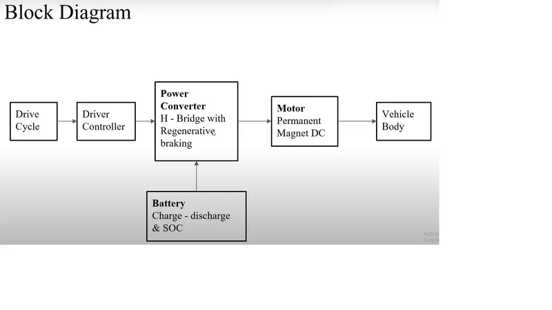 Battery:-
The battery of an electric car can be changed through the use of ordinary grid electricity at a specilaized power station but aside from the conventional lithium-ion battery technologies,there are also other major battery technologies which can be used for electric cars.
Li-Ion Battery:-
A lithium-ion battery or Li-ion battery is a type of rechargeable battery composed of cells in which lithium ions move from the negative electrode through an electrolyte to the positive electrode during discharge and back when charging.Lithium-ion batteries are commonly used for portable electronics and electric vehicles and are growing in popularity for military and aerospace applications. or NMC) may offer longer lives and may have better rate capability. Such batteries are widely used for electric tools, medical equipment, and other roles.
Lead-Acid Battery:-
Lead acid batteries are the most commonly used type of battery in photovoltaic systems. Although lead acid batteries have a low energy density, only moderate efficiency and high maintenance requirements, they also have a long lifetime and low costs compared to other battery types. One of the singular advantages of lead acid batteries is that they are the most commonly used form of battery for most rechargeable battery applications (for example, in starting car engines), and therefore have a well-established established, mature technology base.
Power Converter:-
Power converter can be regarded as the brain or processing unit of an electric vehicle.It basically consists of power electronic devices.It is the one which enable the control of an Electric Vehicle.Because the voltage from the battery is a constant DC and if it is given directly to the motor,the motor would always run at constant speed and we could not achieve the speed control of the motor.This problem is solved by the power converter which consists of inverter or chopper configurations according to the motor used and it employs various techniques such as Vector Field control,PWM etc to control the speed of the motor.
Electric Motor:-
Electric motor is the electro-mechanical machine which converts the electrical energy into mechanical energy. In other words, the devices which produce rotational force is known as the motor. The working principle of the electric motor mainly depends on the interaction of magnetic and electric field. The electric motor is mainly classified into two types. They are the AC motor and the DC motor. The AC motor takes alternating current as an input, whereas the DC motor takes direct current.
PROCEDURE:-
Vehicle Body:-
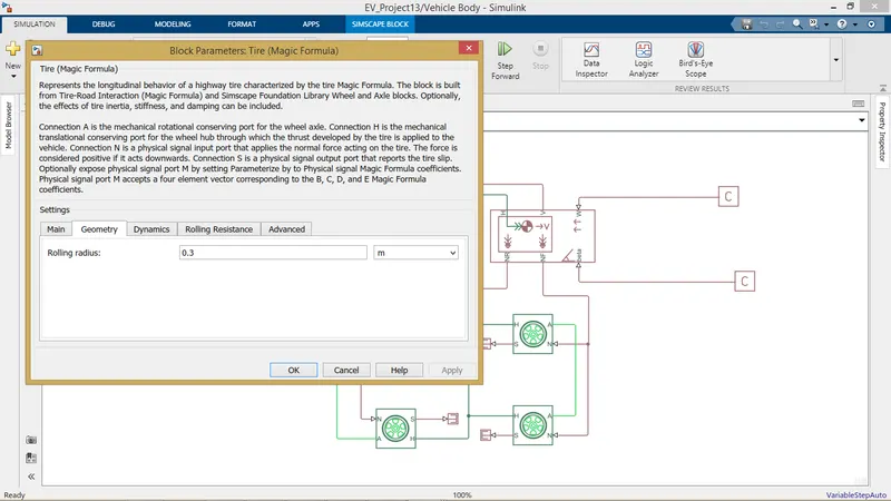
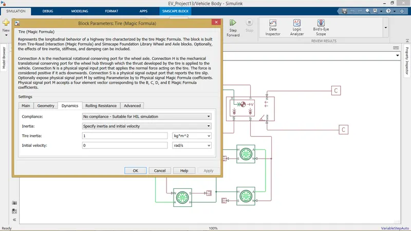
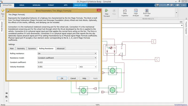
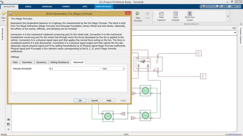
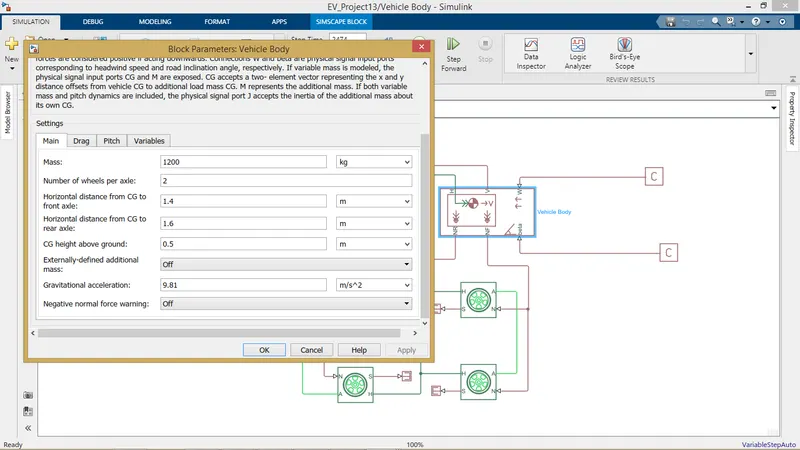
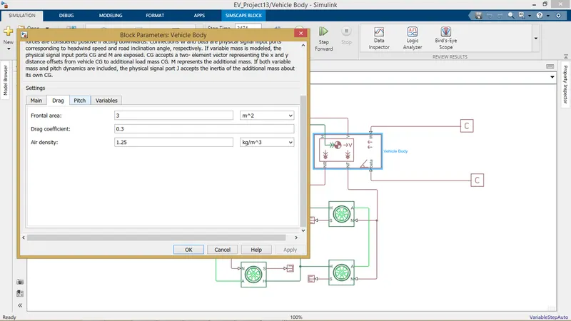
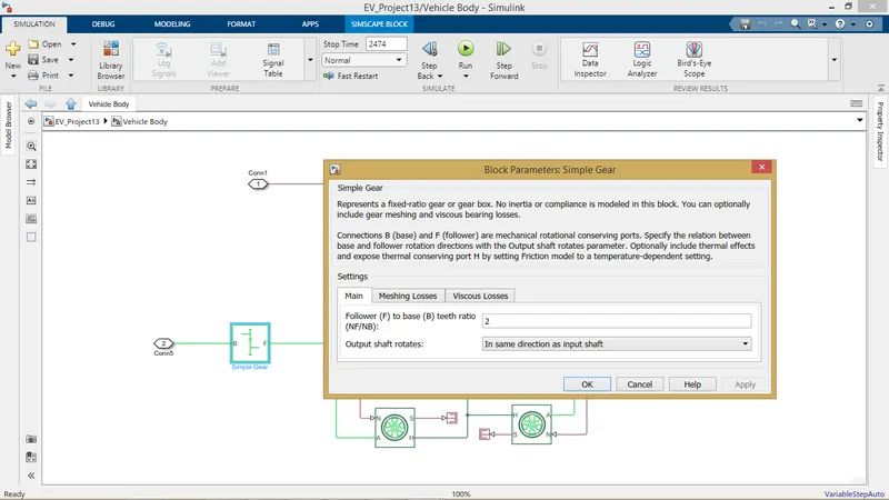
The Vehicle body subsystem consists of ''Vehicle Body" block,"Tires (Magic Formula)" blocks and a "simple gear" block from the simscape library the tires are connected to a common hub from the vehicle body and the axles are connected with in the front tires and the rear tires.The normal forward force and the normal reverse force are given to the front and rear tires respectively.The wind velocity and the angle of inclination of the vehicle are given with the help of physical constants.A simple gear block here simulates the transmissionsystem of the vehicle in asimple way
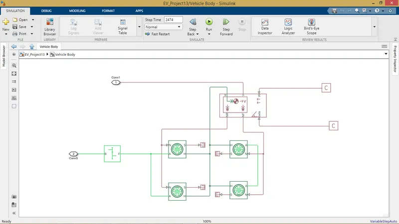
from the data sheet the values are into simulink blocks
Tire:
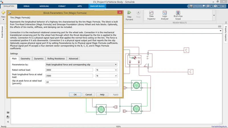
Vehicle body:
Simple Gear:-
Motor Controller Sub-System:-
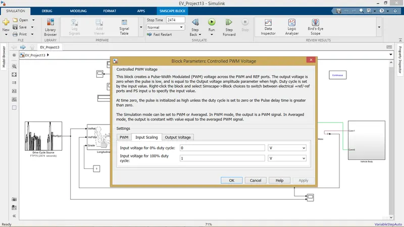
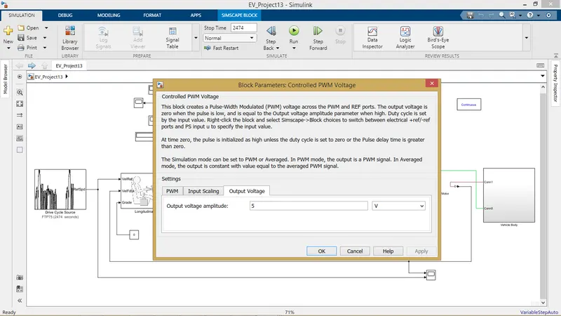
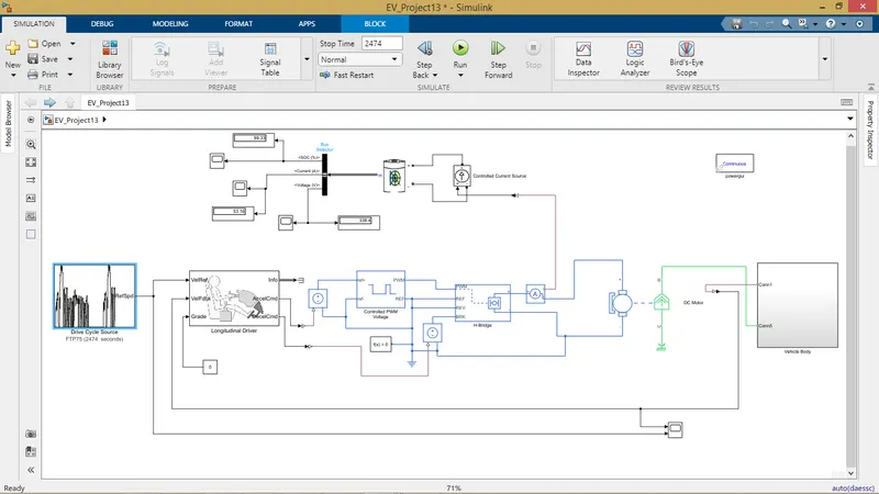
The motor controller subsystem consists of blcks such as "Controlled Voltage Source","Controlled PWM Voltage","H-Bridge" and a solver configuration.Here the acceleration and the deacceleration command are received from the longitudinal driver block and pulse of variable width are produced by the "Controlled PWM Voltage" block are into the H-Bridge.The H-Bridge the gives a voltage to the battery corresponding to the pulse.The varaible voltage across the battery inturn controls the speed of the DC motor.
PWM:-
H-Bridge:-
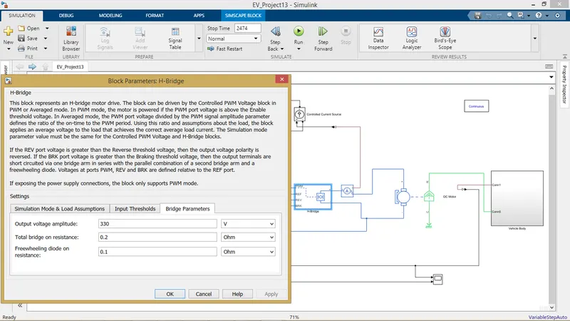
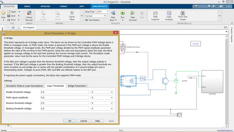
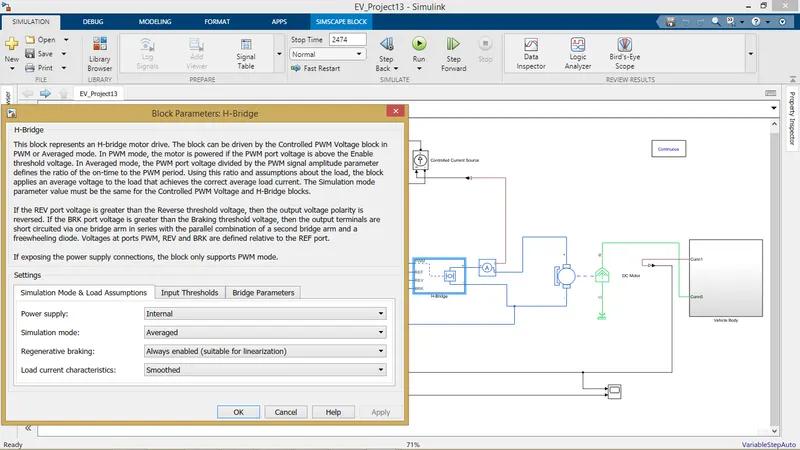
H-bridge is an electronic circuit that reverses the voltage/current at both ends of the load or output to which it is connected. These circuits are used in robots and other real-world applications for DC motor inversion control and speed control, stepper motor control (bipolar stepper motors must also contain two H-bridge motor controllers), most DC-AC converters in electrical energy conversion (such as inverters and inverters), some DC-DC converters (push-pull converters), and other power electronics devices.
H-bridge is a typical DC motor control circuit because its circuit shape resembles the letter H, so it is named with "H-bridge". 4 transistors form the 4 vertical legs of H, and the motor is the horizontal bar in H.
The H-bridge circuit can be built as discrete components or integrated into an integrated circuit and is often used in inverters (DC-AC conversion). Through the opening and closing of switches, DC power (from batteries, etc.) is inverted into AC power of a certain frequency or variable frequency, which is used to drive AC motors (asynchronous motors, etc.).
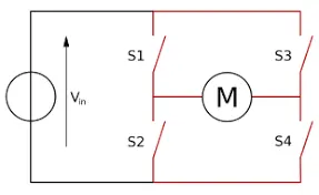
Switch T1, T4 on, T2, T3 off: u0 = Ud.
Switch T1, T4 off, T2, T3 on: u0 = -Ud;
When switching switches T1, T4 and T2, T3 alternately at frequency fS, an alternating voltage waveform (square wave alternating positive and negative) is obtained at the load resistor R with period Ts=1/fS. In this way, the DC voltage E is turned into AC voltage uo. uo contains all harmonics and can be filtered by a filter if a sinusoidal voltage is desired.
The main circuit switches T1 to T4, which is actually an ideal model for various semiconductor switching devices. The common switching devices used in inverter circuits are fast thyristor, turn-offable thyristor (GTO), power transistor (GTR), power field-effect transistor (MOSFET), and insulated gate transistor (IGBT).
In practice, there are losses in switching devices: conduction losses and commutation losses, and gate losses. The gate losses are negligible, while the conduction losses and phase change losses increase with the switching frequency.
DC Motor:-
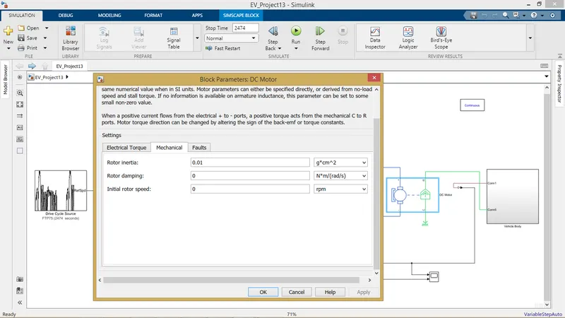
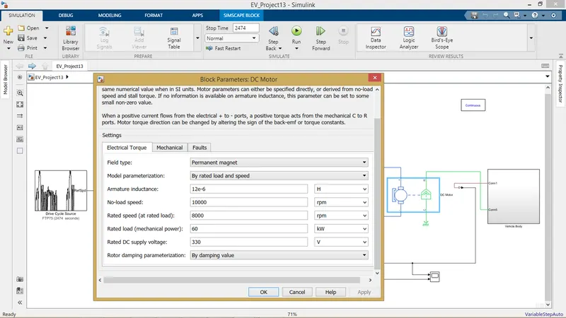
DC Motor Parameters for this simulink model was purelydone by trail and error method so that the vehicle could match with the driving cycle.It would be quite difficult to find such DC motos in real world with good efficiency.But,for the sake of simulation,it is used the DC motor block parameters are as follows:-

Longitudinal Driver:-
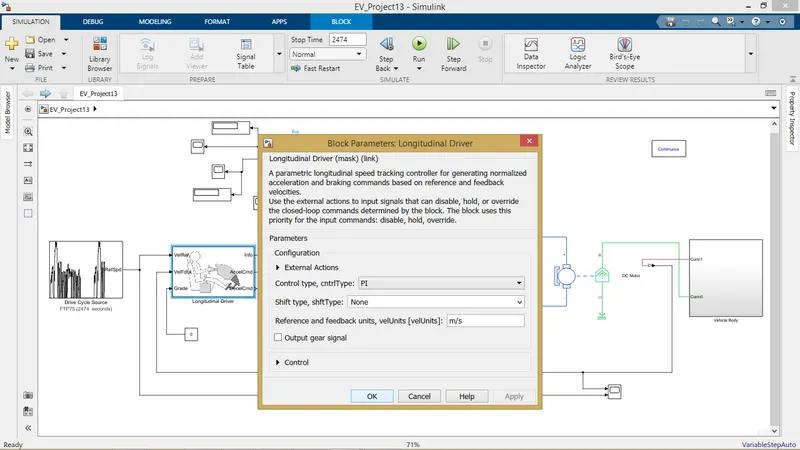
It is aparametric longitudinal speed tracking controller for generating normalized acceleration and braking commands based on reference and feedback velocities.From the simulink model,we could see that the vehicle output speed is fedback and compared with the reference speed(drive cycle) inorder to obtain the acceleration and deacceleration command.
Drive Cycle:-
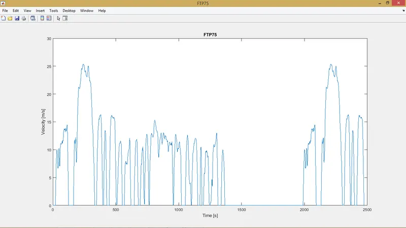
Drive cycle is simply speed vs time graph.It is generally used for various vehicle testing and simulations The drive cycle used in this simulation is the FTP 75
Model:-
Result:-
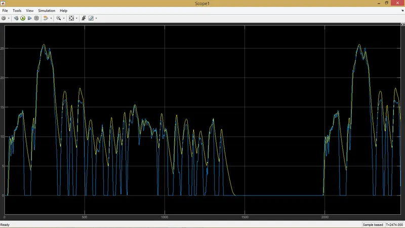
1)Vehicle Speed:-
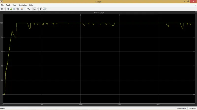
SOC:-
Conclusion:-
The model was succesfully run for simulation under the standard FTP 75 drive cycle The results have been properly analyzed.