Final Project: Design of an Electric Vehicle
EV - 21 FINAL PROJECT
Theory : -
- An electric vehicle (EV) is one that operates on an electric motor, instead of an internal-combustion engine that generates power by burning a mix of fuel and gases.
- Electric Vehicles (EV’s) include, road and rail vehicles, surface and underwater vessels, electric aircraft and electric spacecraft.
- Though the concept of electric vehicles has been around for a long time, it has drawn a considerable amount of interest in the past decade amid a rising carbon footprint and other environmental impacts of fuel-based vehicles.
- An electric vehicle may be powered through a collector system by electricity from off-vehicle sources, or may be self-contained with a battery, solar panels, fuel cells or an electric generator to convert fuel to electricity
The acronym for electric vehicle is EV. Basically, EVs are cars that are partially or entirely powered by electricity.
An electric vehicle is one that runs on electricity and have minimal operating expenses due to fewer moving parts to maintain and are particularly ecologically beneficial due to their usage of little or no fossil fuels (petrol or diesel).
While some EVs used lead acid or nickel metal hydride batteries, lithium-ion batteries are generally regarded the norm for current battery electric cars since they have a longer life span and are good at retaining energy, with a self-discharge rate of just 5% per month.
Electric Vehicles operate by connecting into a charging station and drawing power from the grid. The electricity is stored in rechargeable batteries, which power an electric motor, which moves the wheels. Electric vehicles accelerate more quickly than vehicles powered by traditional gasoline engines because they are lighter.
EVs have 90% less moving components than gas/petrol vehicles. These are the components that keep an EV running
Electric motor/engine | Provides the necessary torque to turn the wheels. It can be either DC or AC; however, AC motors are more prevalent.
Inverter | Converts direct current (DC) electric current into alternating current (AC).
Drivetrain | Electric vehicles feature a single-speed transmission that transfers power from the motor to the wheels.
Batteries are used to store the electricity needed to power an EV. The greater the battery's kW rating, the greater the range. To charge your battery, connect it to an outlet or an EV charging station
The components and functions of electric vehicles vary depending on the vehicle type. The many sorts of electric vehicle components affect how it functions.
In general, a battery electric vehicle (BEV) functions as follows:
-
You press the pedal.
-
The controller collects and regulates electrical energy from batteries and inverters.
-
Once the controller is set, the inverter transfers a predetermined quantity of electrical energy to the motor (depending on the pressure on pedal).
-
The electric motor converts electrical energy into mechanical energy (rotation).
-
The rotation of the engine causes the gearbox to revolve, causing the wheels to turn and the automobile to move.
In addition, there are three distinct EV charging speeds:
Slow | Typically, they are rated up to 3kW. Frequently used to charge overnight or during work. The charging time ranges between 8 and 10 hours.
Fast | Typically, they are rated at either 7kW or 22kW. Car parks, supermarkets, recreational facilities, and residences with off-street parking are common places for them to be built. The charging period is about 3-4 hours.
Rapid | Typically starting at 43kW. Only compatible with EVs that support quick charging. The charging time ranges between 30 and 60 hours.
The range of an EV is determined by the size of its battery (kWh). The larger the kWh of the EV battery, the more power, and the greater the range of the car.
In general, any type of vehicle may be outfitted with an electric powertrain. These are three major instances of what electrification can achieve for vehicle
BATTERY ELECTRIC VEHICLE :
Battery Electric cars are those that are completely electric, have rechargeable batteries, and do not have a gasoline engine. The battery pack, which is recharged from the grid, provides all the energy for the vehicle.BEVs are zero-emission cars since they produce no hazardous exhaust emissions or air pollution threats like typical gasoline-powered vehicles do.
HYBRID ELECTRIC VEHICLE (HEV)
Hybrid Electric Vehicles are powered by both a gas engine and an electric motor.
The battery receives all its energy from regenerative braking, which recoups otherwise lost energy in braking to aid the gasoline engine during acceleration.
This braking energy is generally wasted as heat in the brake pads and rotors of a standard internal combustion engine car. Regular hybrids cannot recharge by plugging into the grid.
PLUG - IN HYBRID ELECTRIC VEHICLE :-
Plug-in Hybrid Electric Vehicles are powered by both an engine and an electric motor. They, like ordinary hybrids, can recharge their batteries via regenerative braking.
PHEVs vary from ordinary hybrids in that they have a considerably bigger battery and can be recharged by plugging into the grid. While normal hybrids can go 1-2 miles before the gasoline engine kicks in, PHEVs can travel 10-40 miles before the gas engine kicks in.
When the all-electric range is reduced, PHEVs behave like ordinary hybrids and may drive hundreds of miles on a single tank of gasoline
ENVIRONMENTAL ADVANTAGES OF ELECTRIC VEHICLES :-
It is hard to write about electric vehicles without mentioning one problem — global warming. The recent years, in particular, has witnessed significant shifts in climate compared to a decade ago, and the situation will only deteriorate if nothing is done.
Electric cars are critical to fulfilling global climate change targets. They play an important role in mitigation strategies that restrict warming to well-below 2°C or 1.5°C, which is consistent with the Paris Agreement's objectives.
However, while EVs emit no greenhouse gases directly, they run on power that is still mostly produced from fossil fuels in many areas of the world. Energy is also used in the production of the electric vehicle, namely the battery.
Simply said, electric vehicles provide cleaner streets, making our towns and cities a better environment for walkers and cyclists. According to EDF, just one electric car on the road may save an average of 1.5 million grams of CO2 over the course of a year.
INVERTER OF POWER
The inverter converts the direct current (DC) on the battery into alternating current (AC), which is then utilized by an electric motor. Furthermore, the inverter on an electric car includes a function that converts the AC while regenerative braking to DC, which is then utilized to replenish the battery. The bi-directional inverter is a type of inverter that is utilized in various electric car types.
CONTROLLER
The controller's primary role is to regulate the flow of electrical energy from batteries and inverters to electric motors. In a nutshell, the controller controls the flow of electrical energy given by the traction battery, as well as the speed of the electric traction motor and the torque it creates. This component will govern how electric cars operate.
ELECTRIC MOTOR
The electric traction motors will turn the gearbox and wheels because the controller delivers electrical power from the traction battery. Some hybrid electric vehicles employ a generator-motor that serves as both propulsion and regeneration
COMPONENTS :
The main components of ev are
1.wheels/tyres
2.Battery
3.Motor
4.Motor controllers
5.Power converters
6.Transmission system
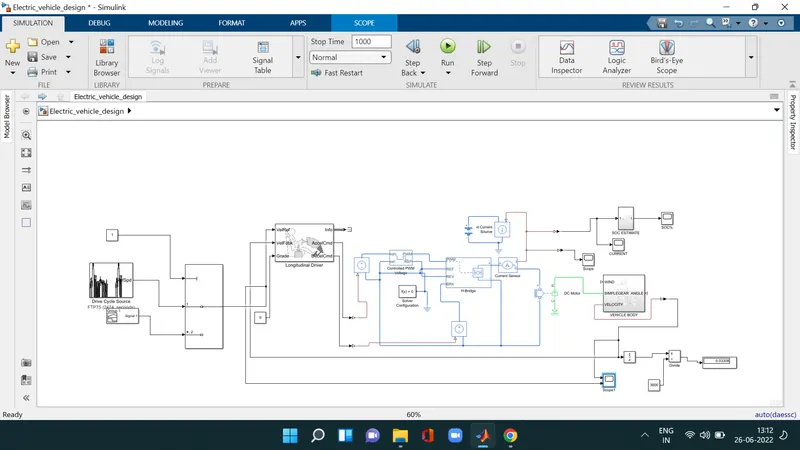
For modelling the whole vehicle in simulink we need to model the above mentioned components seperately and make them work together all the main components available in library of simulink blocks so we add components and configure the parameter working requirements of the model
VEHICLE BODY :
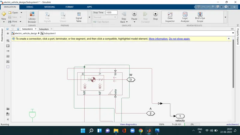
this block contain 6 ports which can be used model various aspects of the vehicle body
Represents a two-axle vehicle body in longitudinal motion. The block accounts for body mass, aerodynamic drag, road incline, and weight distribution between axles due to acceleration and road profile. The vehicle can have the same or a different number of wheels on each axle. Optionally include pitch and suspension dynamics or additional variable mass and inertia. The vehicle does not move vertically relative to the ground.
Connection H is the mechanical translational conserving port associated with the horizontal motion of the vehicle body. The resulting traction motion developed by tires should be connected to this port. Connections V, NF, and NR are physical signal output ports for vehicle velocity and front and rear normal wheel forces, respectively. Wheel forces are considered positive if acting downwards. Connections W and beta are physical signal input ports corresponding to headwind speed and road inclination angle, respectively. If variable mass is modeled, the physical signal input ports CG and M are exposed. CG accepts a two- element vector representing the x and y distance offsets from vehicle CG to additional load mass CG. M represents the additional mass. If both variable mass and pitch dynamics are included, the physical signal port J accepts the inertia of the additional mass about its own CG
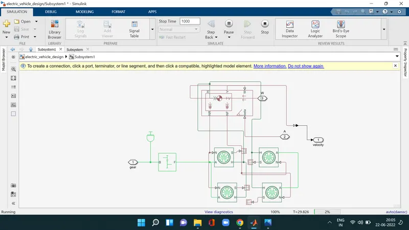
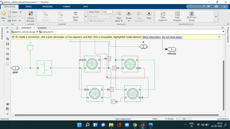
The above blocks are forming the subsystem which serves as a part for the whole vehicle four tyres are connected the right two wheels are the rear wheels and remaing front wheels they are interconnected to the hub of the vehicle body block and their respective axles are connected accoringly we here connected the rear axle with gear as we anted the rear to be wheel drive vehicle here wind velocity port and hill climbing angle ports are connected to the physical constant block which is kept zero
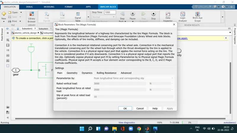
here we can change the geometry dynamics and rolling resistance other characterstics if we want
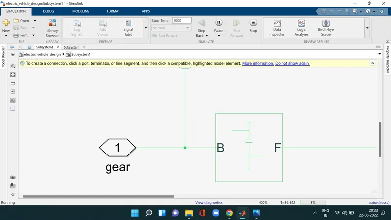
This block models a gear system with fixed gear ratio with no inertia effects however we can modify the messenging of the gear teeth here the follwer to base teth ratio has been set to 2 and output shaft rotates in the same direction as the input shaft
all these blocks are categorised into a single subsystem which we name as vehicle body block which take the mechanical input from the motor and controller block into the gear and displays the velocity body
MOTOR AND THE CONTROLLER SUBSYSTEM
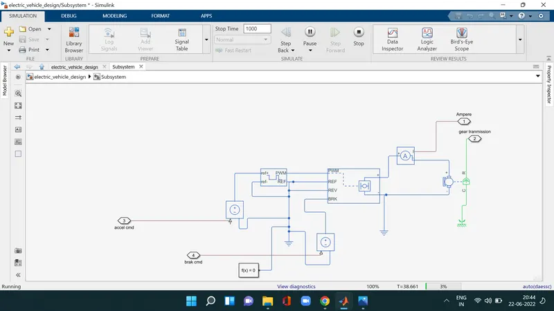
COMPONENTS
1.DC Motor
2.H-bridge
3.Controlled PWM Voltage
4.Controlled Voltage Source
5.Current Sensor
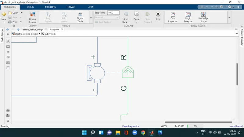
For the ev model i have selected the use a dc motor block because dc motor is easy to model and they have very few parameters to run for a particular application there are two sides of the block the mechanical on the right and electrical side is on the left mech side has two ports c and R and c stands for casing and is stable part and R is rotor which produces thetorque the electrical side has positve and negative side for the voltages applied if positive voltage is applied to the motor block positive terminal of the negative terminal then a positive torque will act from C to R port the direction of the torque can e changed by a sign of the back emf or torque constant here i have connected the c port to mechanical rotational reference because it will be statinary the port is connected to the gear in the vehicle body
H - Bridge :-
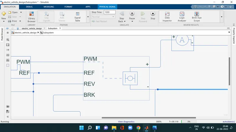
this a power converter whicjh is needed to convert power from correct form and magnitude from oe component to other inase of ev the power converter is needed to provide a dc voltage from the battery of the ev to the dc motor so that it can functioned properly at the required parameters i have used an H brige motor drive as my power converter the left side is the controlling voltage signal and right side terminals to provide the controlled voltage to the dc motor
1.pulse width modulation
2.REF - reference
3.REV - reverse
4.BRL - brake
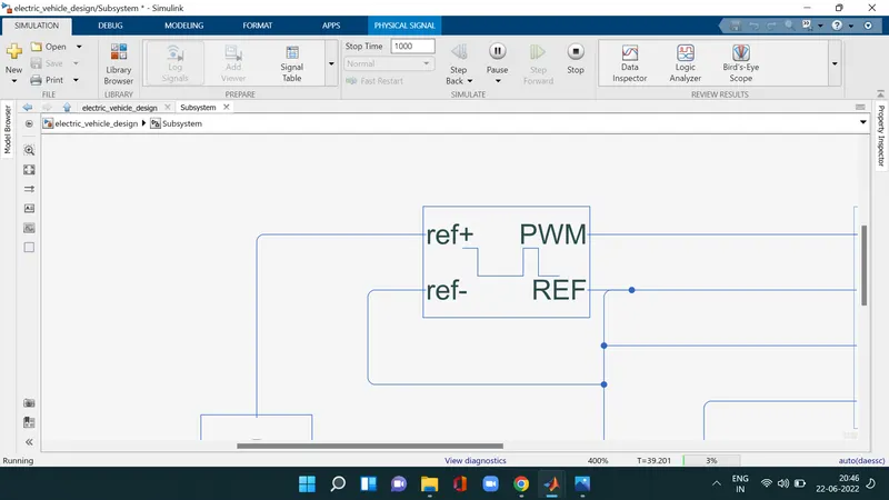
i have used the controlled pwm voltage to provide a controlled pulsewidth modulation voltage to the H-bridge block the pulses are dependent on the voltage created by this blocks duty cycle which is in that ratio time Ton / Toff = duty cycle
controlled voltage source
the block represents an ideal voltage source that is powerful enough to maintain the specified voltage at its output regardless of the current passing through it. The output voltage is V = Vs, where Vs is the numerical value presented at the physical signal port
BATTERY SUBSYSTEM
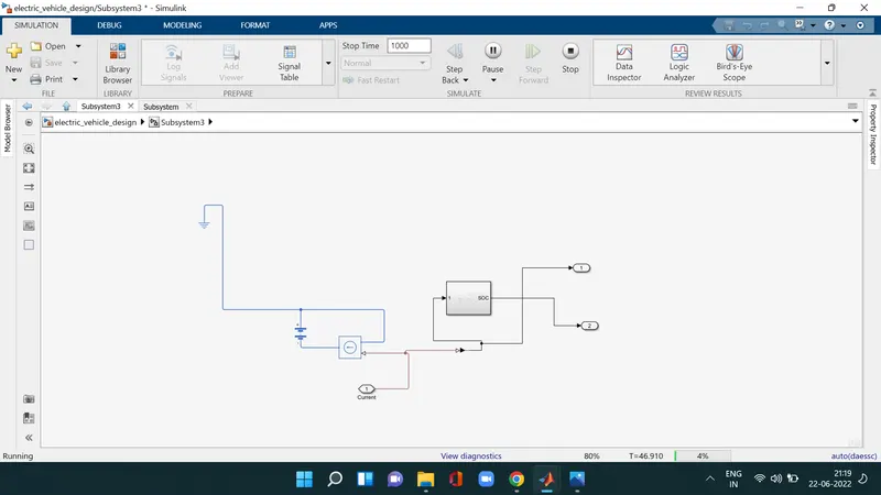
the battery will be the energy store the ev and will contain the electrical energy in dc form and provide this energy to operate
controlled current source : this block is part in the battery subsystem similar to voltage source this block produces ideal current that is powerfull enough to maintain the specified current regardless to the voltage acrossit
current source : this current sensor block represents the an ideal block current sensor and used to convert the current measured in electrical circuit to a physical signal that proportional to acurrent
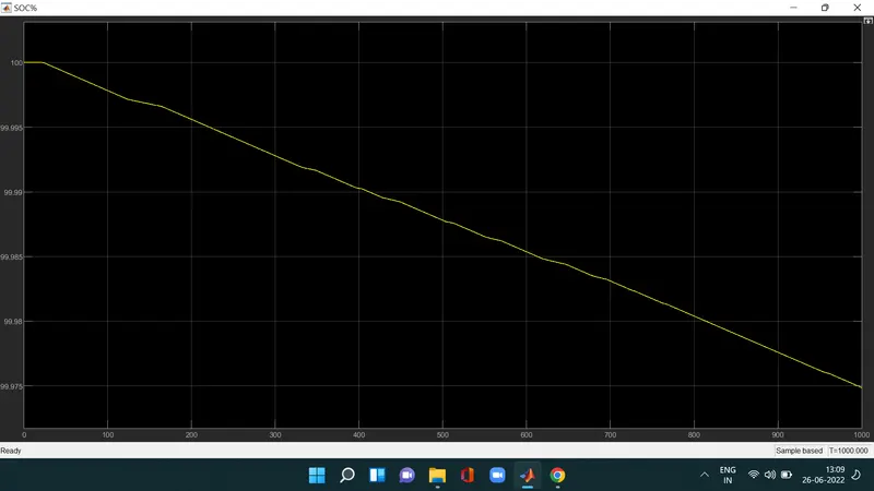
SOC - State of charge
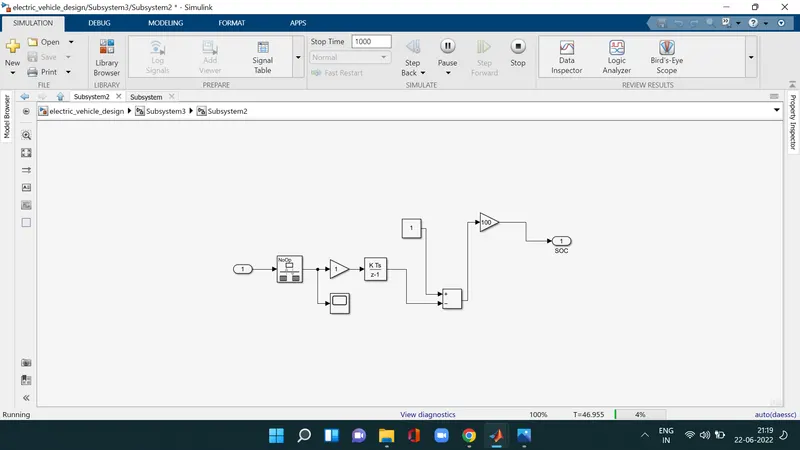
to measure the state of charge of the battery a sub system was created of various blocks the first block is integrator block used to handle data transfer and we use gain blocks discrete time ratio block and scope
LONGITUDINAL DRIVER AND DRIVE CYCLE
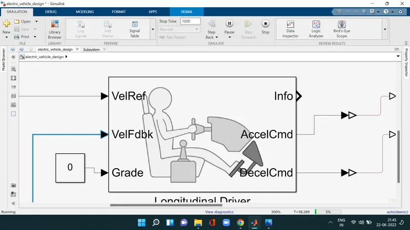
Longitudinal Driver block — Longitudinal speed-tracking controller. Based on reference and feedback velocities, the block generates normalized acceleration and braking commands that can vary from 0 through 1. Use the block to model the dynamic response of a driver or to generate the commands necessary to track a longitudinal drive cycleongitudinal Rider The Longitudinal Rider subsystem implements the rider model that the reference application uses to generate acceleration, braking, gear, and steering commands.
Velref - this stands for the reference velocity and it is the velocity data provided from the drive cycle sorce
Veldbl - this stands for feedback velocity and it is coming from the vehicles body
grade - this port provides the inclination angle on which the vehicle is travelled in degrees
Accecmd - this port provides the acceleration command to the controled voltage source
Deacclcmd - this port provides the deceleration command to the another voltage source
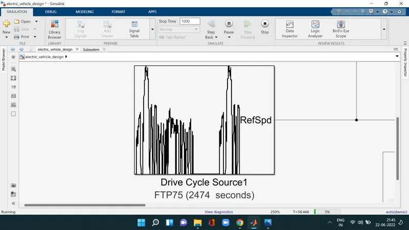
A driving cycle is a generally set of values velocity vs time, which represents how a vehicle travels through a path. In simple words, it would be a velocity vs time graph of a vehicle
vehicle model is simulated in simulation software to obtain the performance prior to actual development. In electric vehicle energy that stored in the battery of EV is transferred to the wheels through a converter, motor, and differential gears.
The transient driving cycle represents an actual pattern of a vehicle which contains acceleration, deceleration, constant speed, etc. Federal Test Procedure (FTP 75) is an example of a Transient Driving Cycle.
RESULT :
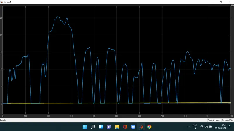
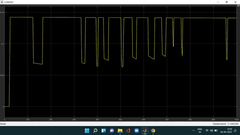
i ran the above drive cycle for my ev model and took thr outputs given from speed current SOC scopes the distance travlled by the vehicle is in the drive cycle is also measured using the display block before the simulation the run time was updated according to the drive cycle time