Final Project: Design of an Electric Vehicle
Student of EV LIVE BATCH 16
AIM : Create a MATLAB model of electric car which uses a battery and a DC motor by using Power tarin Blockset.
Obejectives:
1. System lvel Configurations
2. Model Parameters
3. Results
4. Conclusion
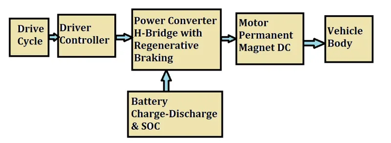
Block Diagram :
The block diagram to design an Electric car is as shown below
SIMULINK MODEL:
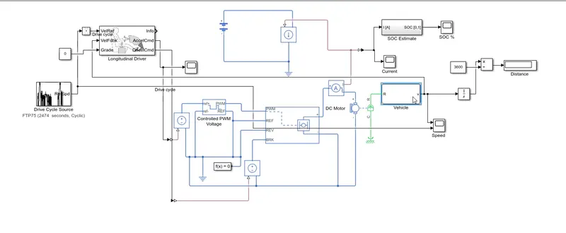
- System level configurations and Model Parameters are as discussed below
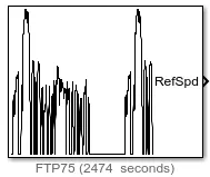
Drive Cycle Source:
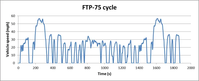
In this design we have selected as FTP75 (2474 seconds ) as drive cycle source.
This block allows us give the drive cycle data, whether it is built in or custom mode by the user.
Here we are using an In built one.
How the vehicle speed is varied with respect to Time is as shown below
Longitudinal Driver:
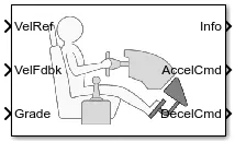
Connections of Longitudinal driver block are as follows
Velocity reference - Drive cycle source
Velocity feedback - connected to vehicle body speed calculation act as close loop feedback to meet the desired speed as per reference input.
Grade - Constant 0
Info - not connected
Accelration command - connected to controlled PWM volatge source through which it is connected to controlled PWM voltage to vary duty cycle according to driver input.
Deceleration command - Connected to Brake of H-bridge to maintain the speed according to the drive cycle and decelerates the vehicle.
The block parameters of Longitudinal driver is as shown below
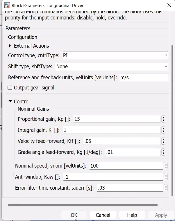
PI (Proportional Integral ) control type is selected. This is nothing but throttle pedal of the driver which will try to match with the input drive cycle given and according to it PI controller will try to match whether acceleration or deceleration as per input given.
H-Bridge:
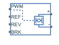
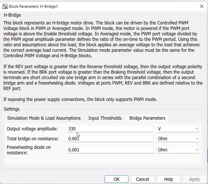
The H-bridge helps in controlloing the power that is input according to the requirement. Ouput provided as converted and controlled voltage as per the parameters given.
Ports connection:
PWM - PWM of controlled voltage source
REF - controlling with reference
REV - controlling with reverse
BRK - controlling the brake and regenerative
+ - Controlled ouptut to thee positive terminal of the motor
- - controlled output to the negative of the motor
Parameters of the H-bridge block are as shown below
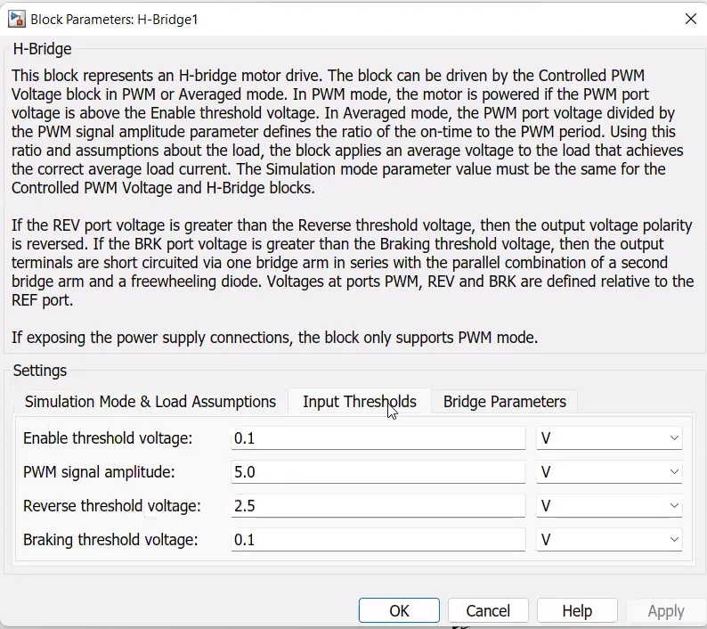
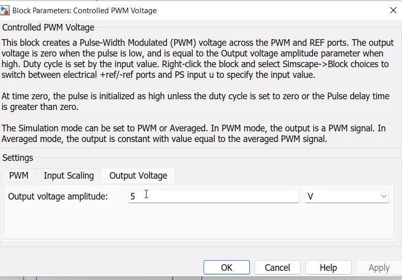
Controlled PWM volatge:
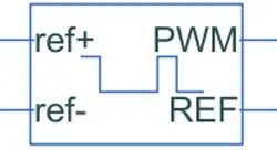
Controlled PWM voltage source to vary duty cycle according to the drivers input.
This blocks helps in keeping the modulated pulses as per the required pulses.so that the operations happens smooth and higher variations are not obeserved.
Ports connections are as follows
ref+ - connected to the acceleration command of the driver model
ref- - connected to the deceleration command of the driver model
PWM - connected to the PWM of H-bridge
REF - connected to the ref of H-bridge
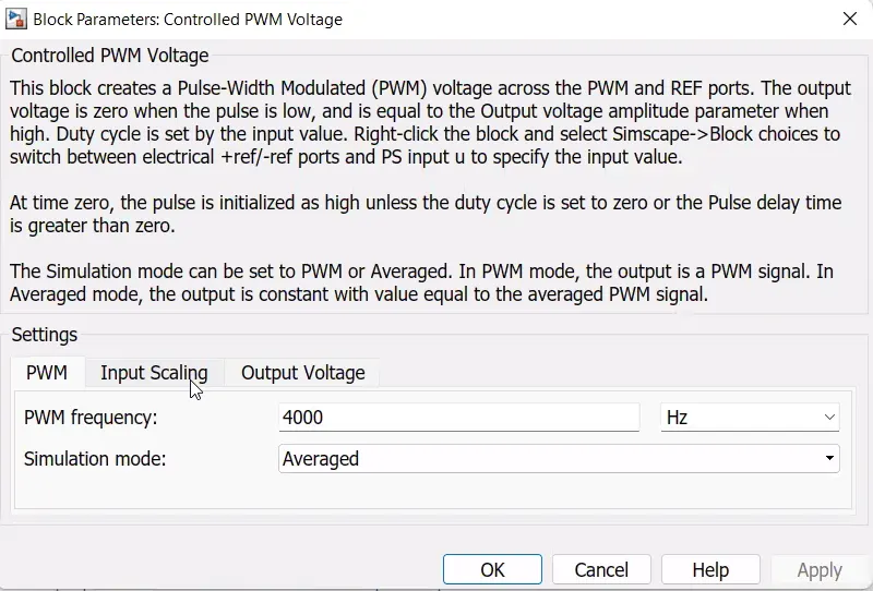
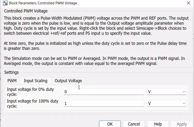
Block parameters are given as follows
DC Motor:
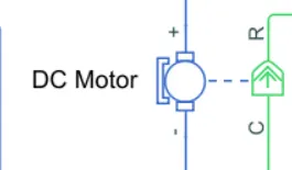
To convert Electrical enrgry to Mechanical energy we are using DC motor.
Connections of motor terminals are as follows
+ connected to the positive termianl of the H-bridge
- connected to the negative terminal of the h-bridge
R connected to the vehicle body R terminal
C connected to the Mechanical rotational reference.
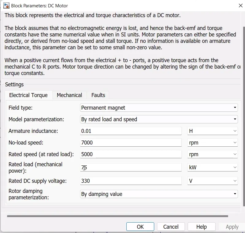
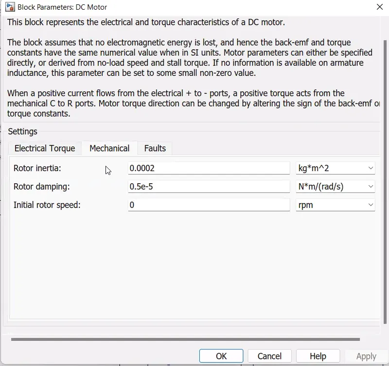
DC motor parameters are given as follows
Battery source:
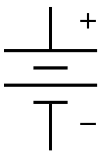
Battery is connected as the source to the model so that the power could be generated and same power is transmitted accordingly to all operating components and load demand of driver.
Terminals of Battery are conncted as
+ connected to Positive terminal of DC mtor along with SOC estiamte block.
- connected to electrical reference.
Complete battery pack:
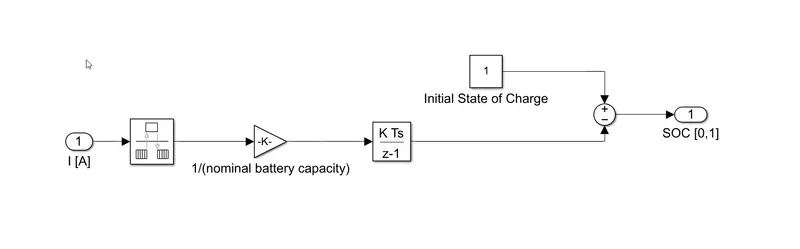
SOC estimation:
Coulomb counting is the technique used to track the state of charge of a battery.
It works by integrating the active flowing current over time to the derive the total sum of energy entering or leaving the battery pack. capacity is measured in Amp-hours.
The SOC block is connected with the battery through controlled current source block from which integrator block counts all the time period values of current, the gain considered at (1/50*3600) Ah capacity of battery , the sum block subtract the SOC from initial set constant block.This gives us the Battery SOC estimation.
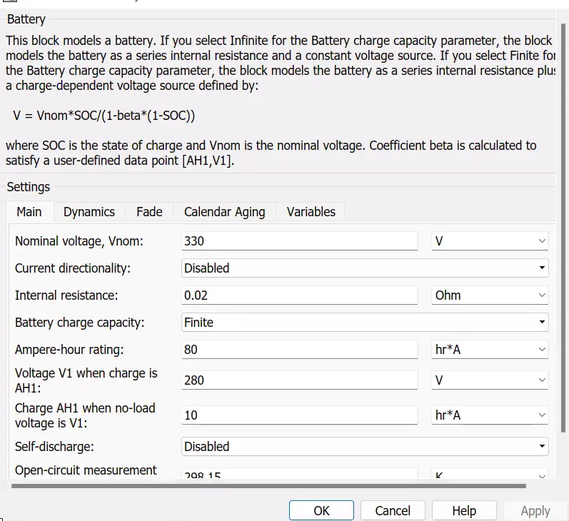
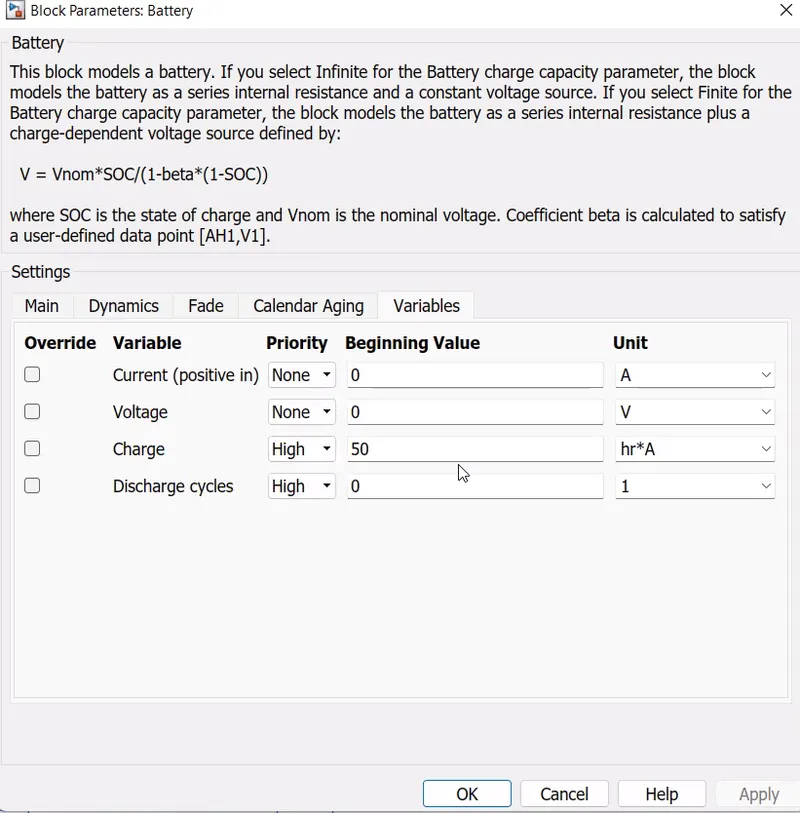
Parameters of battery source are
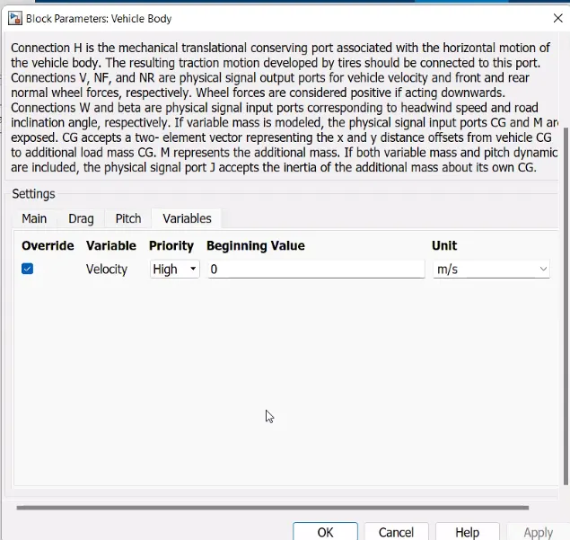
Vehicle body:
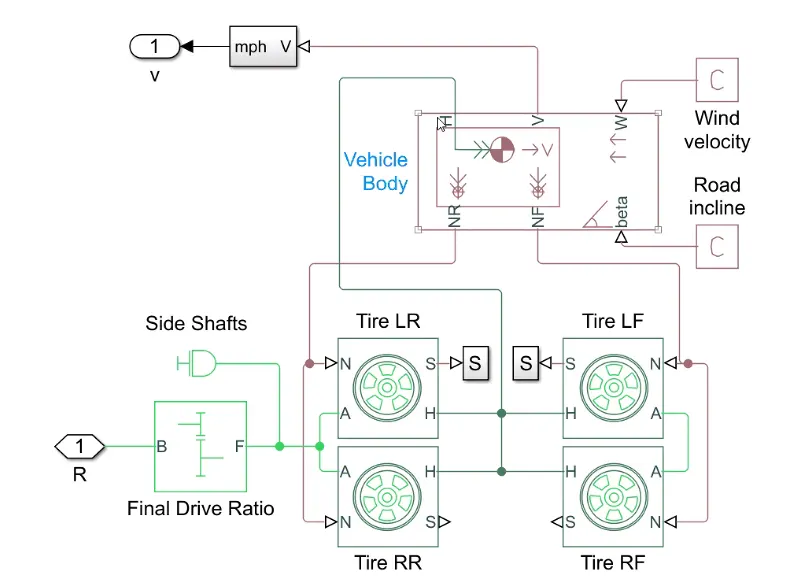
Simple block : For engaging the correct gear at the right duration where required
Vehicle block : Specifications are as mentioned below
Angle : angle could be as the road condition the slope at which the car is running
Wind : The wind could be specified as per the condition where thevehicle has to be driven.
Velocity : The speed of the EV car
NF : The front wheel connection
NR : The rear wheel conection
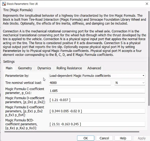
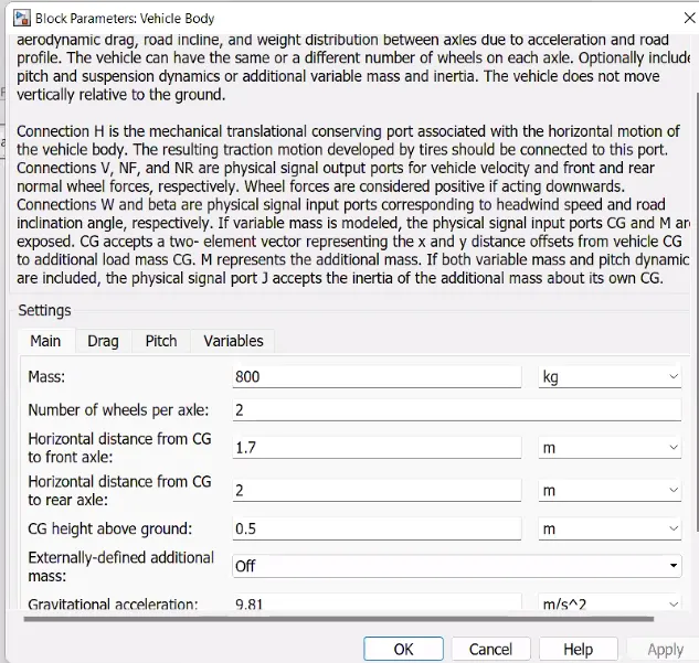
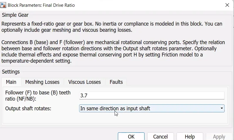
RESULTS:
Here are the results for Given input vales of Drive cycle and according to given block parameters.
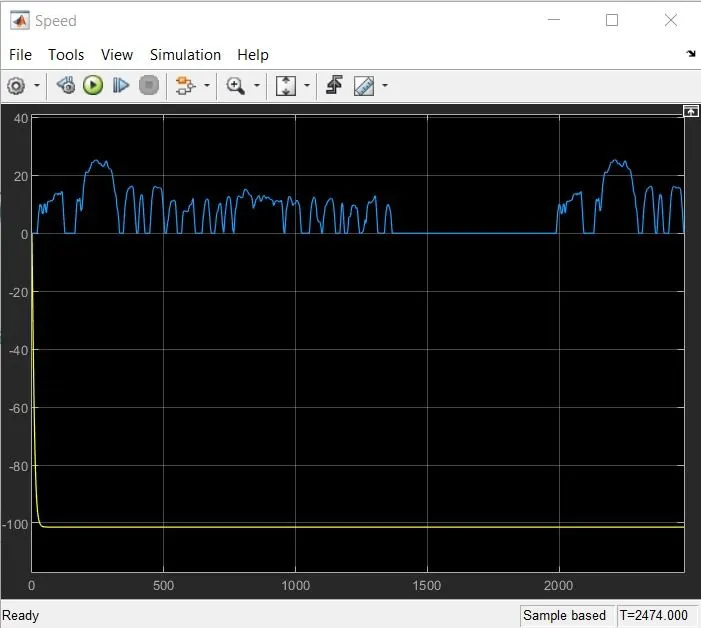
The Speed of Designed Elctric car is varied with respect to time as shown below
It is continously varyiong with respect to time
and we can obesrve that from approximately 1400s seconds to 2000 seconds the car is in Idle comdition (not Moving).
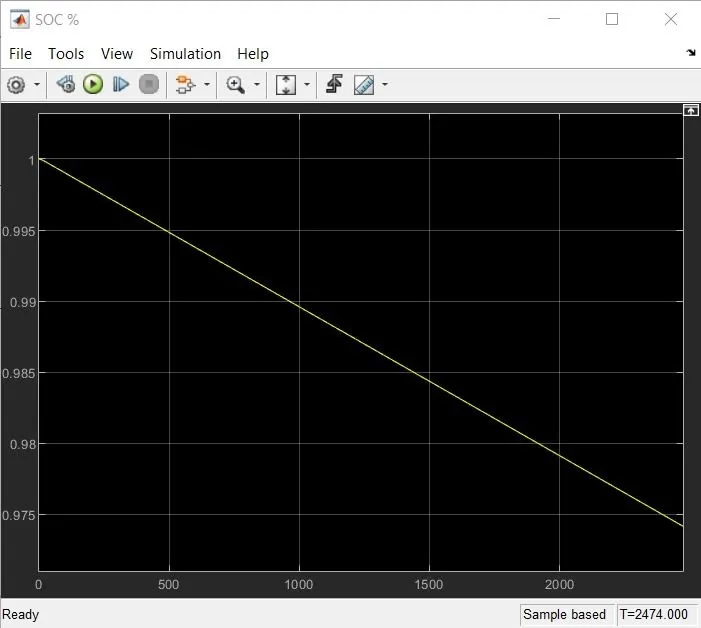
Below plot will tell us how the Battery State of Charge (SOC) is decresaing in a linear manner with respect to time.
At Starting, SOC is 1 that means the battery energy level is FULL.
At end ( 2474 Seconds ) Battery discharges upto certain value and the SOC is approximately 0.97
CONCLUSION:
- The MATLAB Model of an Electric Car which uses a Battery and DC motor has been successfully simulated by choosing the suitable blocks from the Powertrain blockest.
- The Output ( Speed of car ) has been analyzed how it varies according to the given Drive cycel source (FTP 75 .
- SOC ( State of charge ) of Battery is obeserved from above attached plot.