Final Project: Design of an Electric Vehicle
Create a MATLAB model of electric car which uses a battery and a DC motor. Choose suitable blocks from Powertrain block set. Prepare a report about your model including following:
Objectives:
1. System level configurations
2. Model parameters
3. Results
4. Conclusion
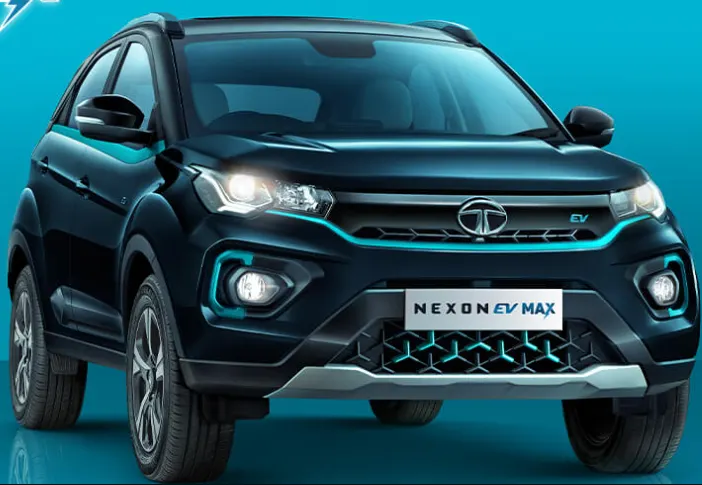
TATA NEXON-EV
Motor (Type)
Permanent magnet synchronous AC motor
Electric motor power (PS)
143*
Electric motor torque (Nm)
250 Nm
Drive modes
Multi drive mode - City, Sport & Eco
Battery pack
40.5 kWh High energy density Lithium ion battery pack
Thermal management system
Liquid cooled
Ingress protection for motor & battery pack
IP 67
Acceleration (0-100 kmph in sec)
9^
Emission
Zero tailpipe emission
Charging Standard
CCS 2
Portable charging cable
IT
Charger options
3.3 kW wall box charger or 7.2 kW AC fast charger
Estimated regular charging time (SOC 10% to 100% from any 15 A plug point)
15** hours
Estimated regular charging time (SOC 0% to 100% from 7.2 kW AC fast charger)
6.5* hours
Estimated fast charging time (SOC 0%-80%) from 50 kW DC fast charger
56* minutes
Block diagram
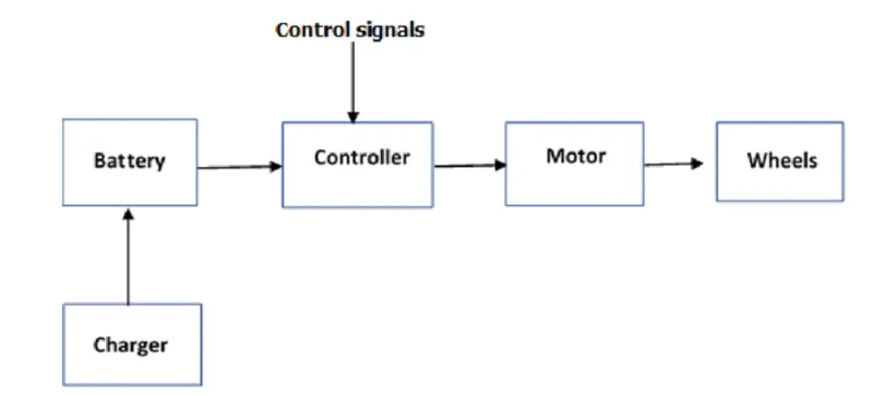
In the designed EV main blocks are battery,drive cycle,controller,DC motor,charger,transmission wheels,feedback control systems,drive cycle is the input data like how a human drive his actual vehicle here FTP75 drive cycle is introduced to make the deisgned vehicle to give that output how it reacts to the drive cycle,the main object to design the EV to obtain the speed by the driver to estimate the state of charge SOC distance travelled by the vehicle,there is SOC block that will estimate the SOC of a battery distance is calculated by speed & time parameters
MATLAB Model of an Electric car:
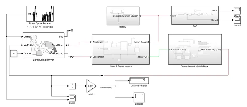
Intially the current flow to DC motor from the battery throught the DC-DC power converter to drive the motor,required voltage will controlled in the controller will follow throught the given drive cycle refrence & run the motor in the required rpm.then the motor power is transmitted to the wheels of a vehicle through a gear box & the controller will take the vehcile speed & compare & control
Model parameters
Motor & control systems
Motor-DC Motor
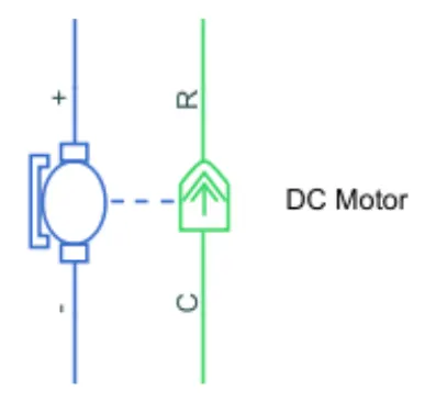
block represents the electric & torque charactertistics of a DC motor.the block assumes that no electromagnetic enrgy is lost & hence the back-emf & torque constraints have the same numerical value when in SI units,motor parameters can either be specified directly or derived from no load speed & stall torque,if no information is available on armature inductance this parameter can set to some small non-zero value.
when positive current flows from the elctrical + to - parts, a positive torque acts from the mechanical C to R ports.motor torque direction can be changed by altering the sign of the back emf or torque constants.motor controller will get input from the longitudial driver .its tasks are to control the speed of the motor & drive according to the input of the drive accordings to the input driver.majorly motor controlled we designed had two main parts named PWM voltage genrator & H-bridge
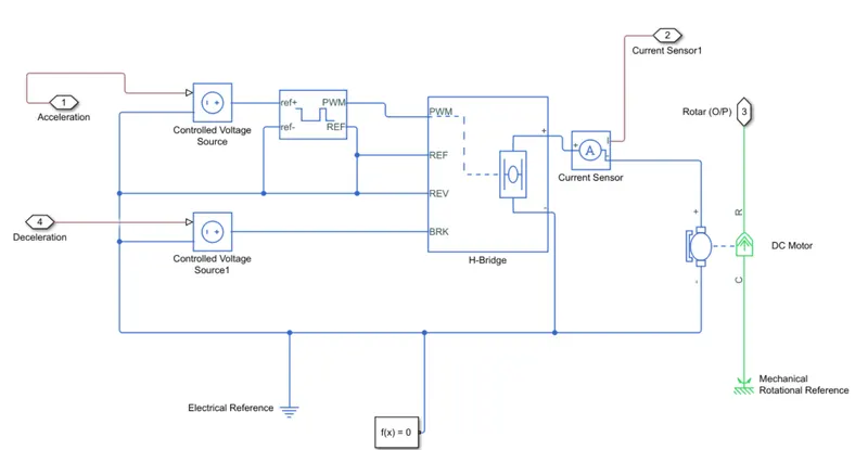
input 1 getting from the acceleration of a longitudinal driver & it is given to a controlled voltage source block where its input to the controlled PWM voltage.it will generate a PWM signal in such way that H-bridge will generate the required voltage to operate the DC motor for thr given driver input.PWM voltage block negative refrence & REF of H-bridge respectively,H-bridge is a motor controller that has IGBT components aligned in the shape H & will operate only two at a time respectively to the input of the signal from the PWM block.when deceleration occur this H-bridge will give an output from the positive & negative terminals are later connected to the DC motor & battery,all these components are the simscape electrical components so they need a connection need a connection to the solver configuration block which helps to solve this simulation
Battery
the battery is required to power the controller & motor.the controlleruses the battery power according to produce the input given by the motor to obtain max.speed,battery is also used to power every electrical component in the vehicle,battery has two stage one is charging & another one is discharging state,battery capacity 80AH
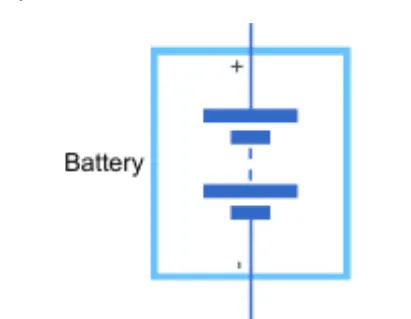
if you select infinite for the battery charge capacity parameterblock models the battery as a series internal resistance & constant voltagesource ,if you select finite for the battery charge capacity parameter block models the battery as a series internal resistance plus a charge-dependent voltage source defined by:
V=Vnom*SOC/(1-beta*(1-SOC))
SOC-state of charge & Vnom is the nominal voltage.coeffeiceint beta is calculated to statisfy by a user defined data point
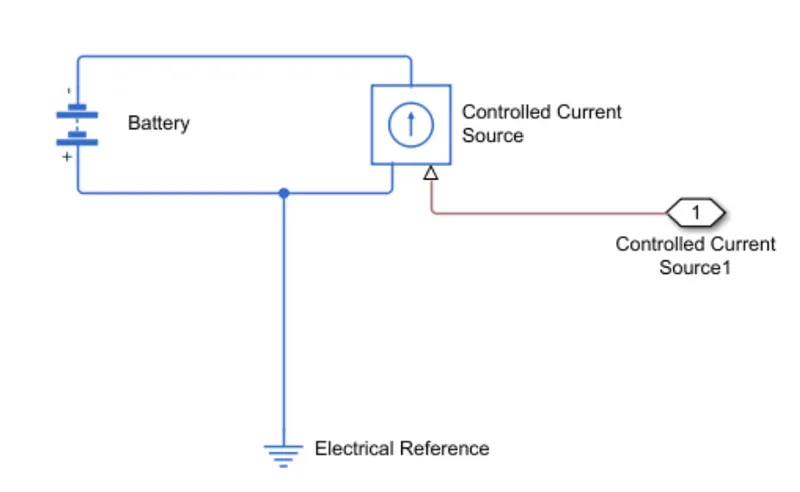
battery has a positive & negative terminal which is given thevoltage controlled source where the battery consumption is controlled by the motor controller & then given to SOC of the battery
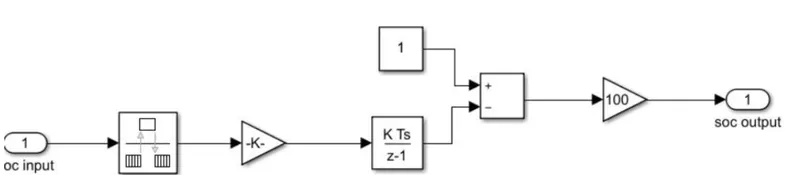
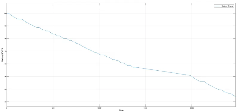
STATE OF CHARGE:it is the percentage or level of battery presents after certain travel or consumption of battery charge by the vehicle.In the designed vehcile battery charge or SOC is calculated by giving it to the rate transition & then to gain where 1/(nominal battery capaciy) then to a discrete -time intergerator & it will get minus from the 1 as it is considered a 100% battery & it is multiplied with 100 to get the percentage of battery present ,majoirty blocks blocks are simscape blocks where physical to simulink convertor is used to convert the physical signal from simscape block to simulink
Drive cycle:driver's input to a vehicle it is replace how a driver will drive a vehicle.these drive cycles are standard drive cycle which is used to test vehicle perfornaces,these drive cycle will have high speed low speed braking conditions in it.there are different types of drive cycles like WOT,FTP75 ets,here I tries FTP 75 drive cycle source
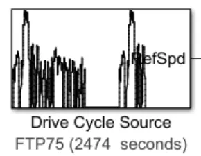
generates a standard or user specified longitudinal drive cycle,block input is the vehicle longitudinal speed.use the fault tracking parameters to identify the drive cycle faults within specified speed & time tolerances
Drive controllers:Parametric longitudinal speed tracking controller for genrating normalized acceleration & braking commands based on refrence & feedback velocities,used the extrnal actions to input signals that can disable hold or override the closed loops commands determined by the block ,uses this prority for the input commands disable hold over ride,drive cycle is connected to a longitudinal driver ,has six ports - velocity,refrences velocity feedback,grade info,acceleration & decelrations
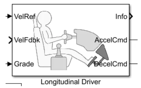
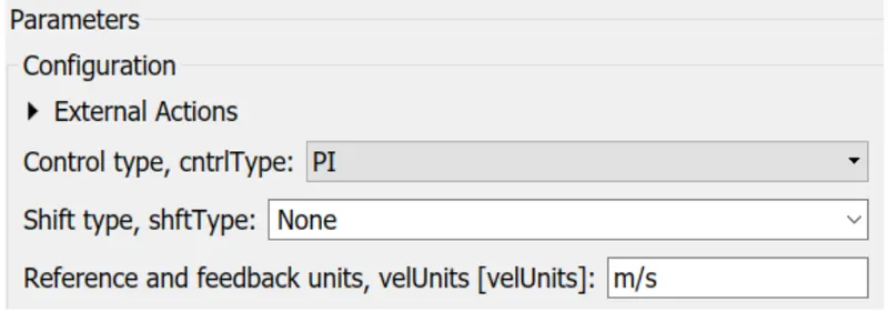
Velocity ref.is given by the drive cycle data & Velocity feed back is given by the output of the motor.these two will get compar acceleration or deceleration output will be given to motor controller.accelcmd is given the PWM generator block & decelcmd is given to the regenrative part of the H-bridge which uses to genrates regenrative braking,info is used to get any other data from a longitudinal driver block,grade is to give input of gradeability to the driver block,helps to genrate /regenrate the driver'conditions of te vehicle using the driver cycle block.
Controlled PWM voltage source
block creates a pulse width modulatted voltage across the PWM &ref parts ,output voltage is zero when the pulse is low & is equal to the output voltage aplitude parameter when high ,duty cycle is set by the input value at time zero the pulse is intialized as high unless the duty cyle is set to zero or the pulse delay time is greater than zero,simulation mode can be set to PWM or avergaed in PWM mode output is a PWM signal,in averaged mode output is constant with value equal to averaged PWM signal.Power converter ,block can be driven by the controlled PWM voltage block in PWM or avergaed mode
POWER CONVERTER
H-bridge,block driven by the controlled PWM voltage block in PWM or averaged mode.in PWM mode motor is powered if the PWM port voltage is above the enable threshold voltage,in average mode PWMport voltage divided by the PWM signal amplitude parameter defines the ratio of the on-time to the PWM period.using this ratio & assumption about the load the block applies an average voltage to load that achieves correct average load current ,simulation mode parameter value must be the same for the controlled PWM voltage& H-Bridge blocks,If REV port voltage is greater than reverse threshold voltage,then the output voltage polarity is reversed ,if the BRK port voltage is greater than braking threshold voltage the the outputterminals in series with the parallel combination of a second bridge arm & a frewheeling diode,voltage ports PWM,REV & BRK are defined relative to the REF part,if exposing the power supply connections the block only supports PWM mode.
Vehicle body & transmission
Motor will produce the rotational output which will give the vehicle body & transmisson system,rptational output is taken by the gear system here to maintain the constant speed throught out the transmission without any loss in speed from the motor to tries,below diagram show hoe it is inside the vehicle body & transmission system & in the main design it is refreed just only as transmission ,wheel drive transmission system
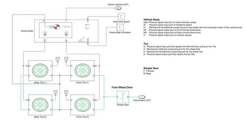
gear output is given to axles of front tries in the circuit it is shown that gear is connected to the front wheels & front tries are connected to rear tires thus vehicles moves forward.N is the normal force caused by the tires & it is given to the vehcile body normal force port .the vehcile body has an H-Hub,S-tire slip,N-normal force ,A-axel connection wind velocity inclination angle.the tires hub is connected to a constant bloxk & the beta inclination angle is connected to other constant block where we can assign wind velocity 7 inclination angle as per requirement.velocity is the outputport where we can get at which spedd the vehcile is moving ,velocity is taken out to the get the distance trvelled & state of change
Results:
Distance travelled
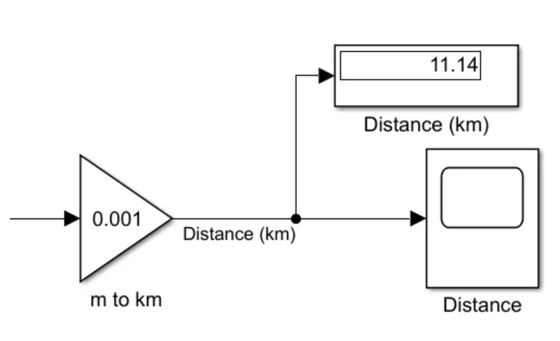
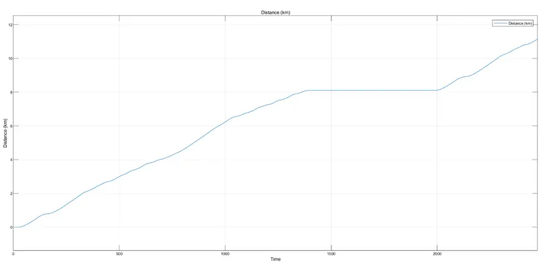
Distance obtained for a given FTP75 drive cycle with 80AH battery capacity is able to cover 11.4Km distance
State of charge
Speed travelled
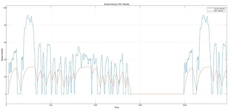
Vehicle speed performance we can conclude that vehcile has attend its max speed ,there is delay in decceleration & acceleration.
hence EV has obtained an output according to the FTP75 drive cycle & it can be tested for any drive cycle by selecting in the drive cycle block,