Final Project: Design of an Electric Vehicle
Create a MATLAB model of electric car which uses a battery and a DC motor. Choose suitable blocks from Powertrain block set. Prepare a report about your model including following:
Objectives:
- System level configurations
- Model parameters
- Results
- Conclusion
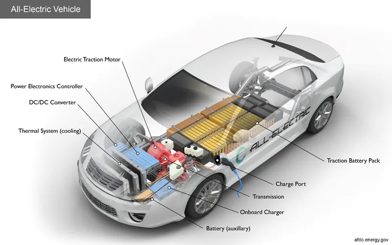
All-electric vehicles (EVs), also referred to as battery electric vehicles, use a battery pack to store the electrical energy that powers the motor. EV batteries are charged by plugging the vehicle in to an electric power source. Although electricity production may contribute to air pollution, the U.S. Environmental Protection Agency categorizes all-electric vehicles as zero-emission vehicles because they produce no direct exhaust or tailpipe emissions.
A vehicle with an internal combustion engine can be converted to an EV by completely removing the engine and adding a battery pack, one or more electric motors, high-voltage cables, and instrumentation. To maximize EV driving range, such conversions are often performed on smaller, lighter-weight vehicles. Careful consideration should be given to the space available to package added batteries and electric motors, along with the ability of the original chassis to support the added weight and placement of those components while still meeting requirements for emissions and crashworthiness.
Battery (all-electric auxiliary): In an electric drive vehicle, the auxiliary battery provides electricity to power vehicle accessories.
Charge port: The charge port allows the vehicle to connect to an external power supply in order to charge the traction battery pack.
DC/DC converter: This device converts higher-voltage DC power from the traction battery pack to the lower-voltage DC power needed to run vehicle accessories and recharge the auxiliary battery.
Electric traction motor: Using power from the traction battery pack, this motor drives the vehicle's wheels. Some vehicles use motor generators that perform both the drive and regeneration functions.
Onboard charger: Takes the incoming AC electricity supplied via the charge port and converts it to DC power for charging the traction battery. It also communicates with the charging equipment and monitors battery characteristics such as voltage, current, temperature, and state of charge while charging the pack.
Power electronics controller: This unit manages the flow of electrical energy delivered by the traction battery, controlling the speed of the electric traction motor and the torque it produces.
Thermal system (cooling): This system maintains a proper operating temperature range of the engine, electric motor, power electronics, and other components.
Traction battery pack: Stores electricity for use by the electric traction motor.
Transmission (electric): The transmission transfers mechanical power from the electric traction motor to drive the wheels
Block Diagram of EV vehicle
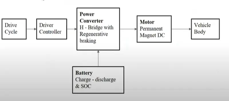
Basic Model of EV vehicle
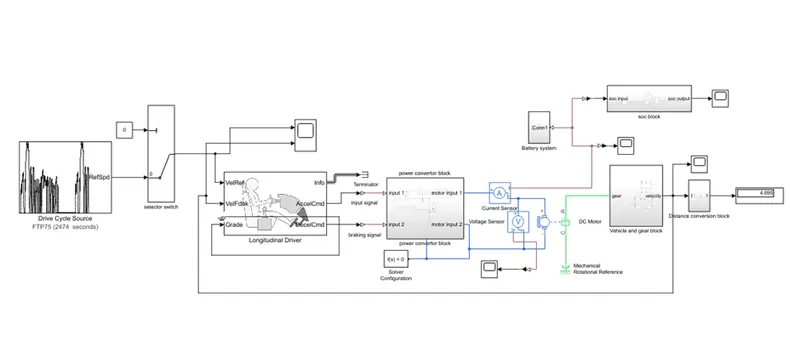
In this above model consist of subsystem there are.
- Drive cycle
- Longitudinal Driver
- Power converter model
- Dc motor
- Vehicle body
- Battery block
- State of charge
- Distance travelled
PROCEDURE:
- Drive cycle:
A drive cycle is typically represented by a series of data points which plots vehicle speed against time. Driving cycles are produced to assess the performance of vehicles in various ways, including fuel consumption and pollutant emissions.
Different type of drive cycle
- FTP75
- Wide open throttle
And many more drive cycle are present and also, we can also do our own drive cycle the can be speed or velocity vs time. That can be load in program and also use the signal builder block and slider switch and scrip file also we use input as a drive cycle.
In this model we can consider for this model FTP75 Drive cycle can used.
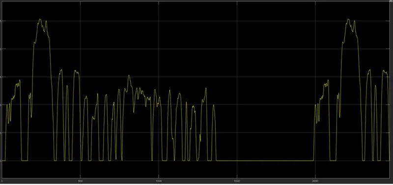
The FTP75 Drive cycle was to run 2474 second we can run this model.
- Longitudinal Driver
The Longitudinal Driver block implements a longitudinal speed-tracking controller. Based on reference and feedback velocities, the block generates normalized acceleration and braking commands that can vary from 0 through 1. You can use the block to model the dynamic response of a driver or to generate the commands necessary to track a longitudinal drive cycle.
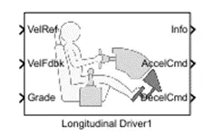
- it is a parametric longitudinal speed tracking controller for generating normalized Acceleration and Braking commands based on reference and feedback velocities.
- The VelRef port is the reference velocity port where the input drive cycle data is fed.
The VelFdbk port corresponds to the feedback velocity. The actual velocity output given by the vehicle body is connected here by comparing the actual (feedback) velocity with the reference velocity, the driver block generates acceleration and braking signals in order to. Minimise the error between the two concerned velocities
Grade corresponds to the grade angle. For this simulation, no inclination is considered and hence, block with value O is connected. We are not concerned grade there for we are used “0”.
Info gives the output for the bus signal for different block calculations like difference in reference vehicle speed and vehicle speed, etc this INFO we will not used this terminal and for that we will connect the PS terminator re connected.
AccelCmd & DecelCmd correspond to the acceleration and deceleration commands generated respectively and are connected to the corresponding ports of the Controlled PWM Voltage block. AccelCmd will given to the PWM power convertor block and DecelCmd given to Braking input.
- Here, the selected control type is PI. Accordingly, the block implements proportional-integral (PI) control with tracking windup and feed-forward gains. Constant
- Power converter model:
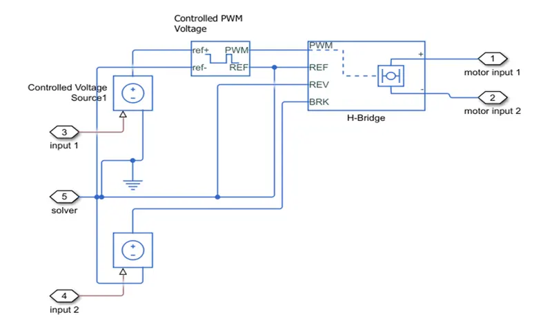
The power converter block we can used in that we can used PWM power converter. In PWM power converter consist of following components, there are following.
- Controlled PWM voltage
- H bridge
- Controlled voltage source
- Controlled PWM voltage:
The input given from the Longitudinal Driver to the controlled PWM voltage.
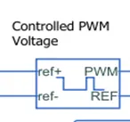
The above fig shows the controlled PWM voltage the ref+ and ref- will give through the controlled voltage source the controlled voltage source connected to the Longitudinal Driver when driver acceleration given the controlled voltage source scene the signal and that connect to the controlled PWM converter. And the output of the controlled PWM voltage connected to H bridge ckt.
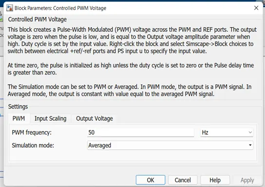
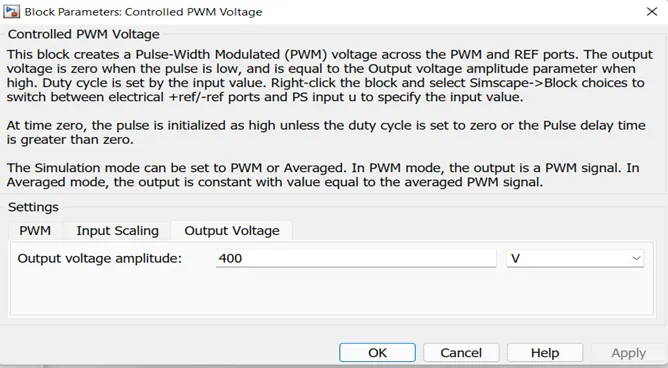
The above fig shows the set values of Controlled PWM voltage. Frequency as 50Hz. And output voltage was 400v
- H-bridge
This block represents on H-bridge motor drive. The block can be driven by the Controlled PWM Voltage block in PWM or Averaged mode.
- In PWM made, the motor is powered if the PWM port voltage is above the enabled threshold voltage. In Averaged mode, the PWM port voltage divided by the PWM signal amplitude parameter defines the ratio of the on-time to the PWM period.
- Connection REF is for the reference input. This combined with the PWM connected will form the pulse input for pluses H-bridge
Here, the REF input is connected to the Electrical Reference (ground).
- Connection REV corresponds to the reverse motion of the motor which essentially means, the backward motion of the vehicle. Here, the backward motion of the vehicle is not accounted for and so, the port is connected to the electrical reference.
- Connection BRK is for the braking of the vehicle.
- Since, the PWM mode results in a huge amount of simulation time, Averaged mode is selected for this simulation
- Load current characteristics are considered to be smoothed here.
- Also, the regenerative braking is an abled for the simulation This means, when the vehicle starts decelerating. corresponding amount of charge will be ted back to the battery. Accordingly, the BRK input is connected to a Controlled Voltage Source. This will generate emf corresponding to the intensity of brakes applied and fed the power back to the battery.
- the braking given through the controlled voltage source then braking applied that time motor work as a generator and it goes in to regenerative braking mode. And that time battery charge.
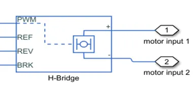
The above fig shows the H bridge
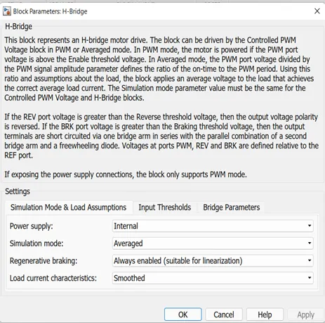
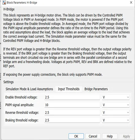
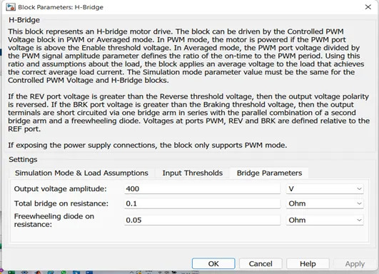
The above fig shows the we set the parameter in H bridge block given and we set the H bridge was 400v given.
- Dc motor
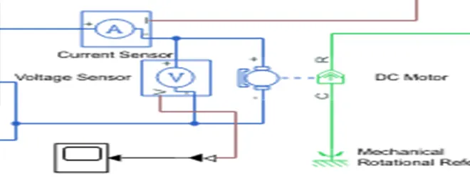
The above fig shows the DC motor connection.
The H bridge output connected to the motor +ve and -ve terminal through the current sensor in series with stator and voltage sensor connected to the stator in parallel connected to determining voltage and current across stator. And connected to solver configuration block.
The rotor side connected R is connected to the gear box and vehicle body and C is connected to the mechanical rotational reference.
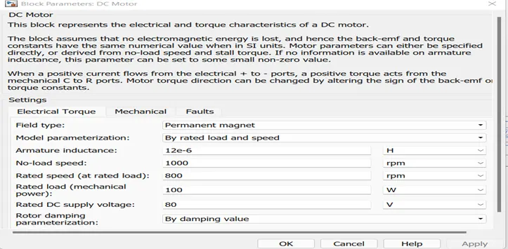
The above fig shows the DC motor given parameter.
- Vehicle body:
According to the question I was consider car 4-wheel drive and if E’auto considered the we take 3-wheel drive. For this example, we are considered car it is consists of 4 wheels and two are front and two are rear wheels and motor are connected to rear wheels.
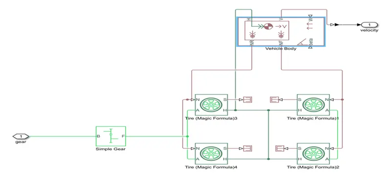
- Tire (Magic Formula)4
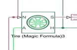
The vehicle is assumed to be a front axle driven (4 wheels 2 on each axle). • The wheels are modelled using simple Tire (Magic formula) Simulink blocks
- The N port of the tire corresponds to the Normal Reaction acting on it.
The A port corresponds to the Mechanical Rotational conserving port for the wheel axle. Thus, both the wheels on the same axle should form a connection through their respective A ports. Connection H corresponds to the Mechanical Translational conserving. Port for the wheel hub through which the thrust developed by the tire is applied to the vehicle. Thus, all the 4 wheels form a connection through their respective H ports and this is in turn connected to the translational hub of the vehicle body. The connection S represents the output port for slip of the tire.
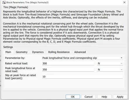
- The tires are parameterized by Peak.longitudinalforce and. corresponding slip The other block parameters such as - rated vertical load, peak longitudinal force at rated load and sip at peck force at rated load - are kept with their default values
- The tire radius is given as 0.3 m as default values.
- Vehicle body

- This block basically represents a two-axle vehicle body in longitudinal motion The block accounts for
- Body of mass
- Aerodynamic drag
- Road incline
- Weight distribution between axles due to acceleration
- Road condition
- Here, the connection H is the mechanical translational conserving port hub. NF & NR correspond to the output ports for normal. reaction forces on front axle and rear axle wheels respectively. Connection V represents the actual output. translational. velocity. Of the vehicle beta is the road inclination angle & W corresponds to the headwind. Speed (headwind - direction opposite to that of vehicle).
- The gross weight is given to be 800 kg.
- The geometric parameters of the vehicle are given as-
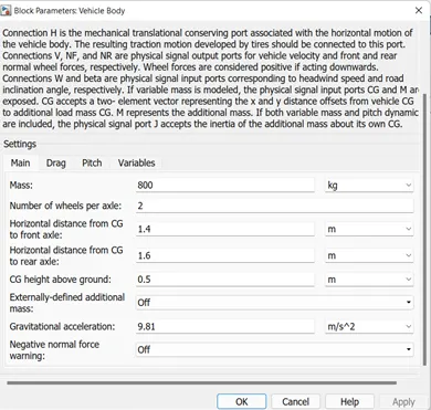
- Gear system:
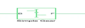
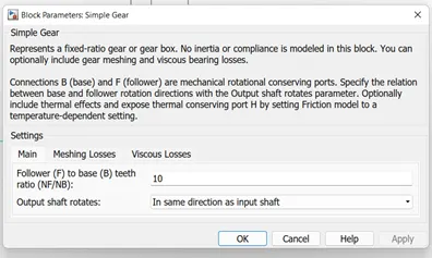
The input for this subsystem is taken as the Rotational speed of the motor. This input is fed to the front ale through a Simple Gear representing the Final Drive Ratio of 10 Here, the rotational direction of the output shaft is kept the some as that of the input shaft Also, no meshing losses are considered for the simulation.
- Battery subsystem:
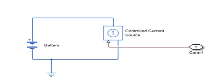
The above fig shows the battery connected to controlled current source. The battery +ve and -ve are connected to the controlled current source and connected to the motor current sensor.
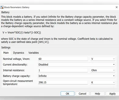
The above fig shows the battery data given to battery system input voltage give 60v and remaining values are default values.
- BATTERY STATE OF CHARGE:
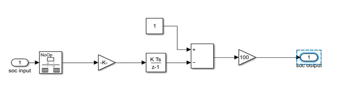
The above fig shows state of charge of battery.
The output of the battery connected to SOC block in this block we can see the how much battery how much of the battery will discharge and how much of the battery charge remain. In gain value should be such as (1/nominal voltage* time).
OUTPUT OF EV VEHICEL MODEL.
- Battery status of charge output:
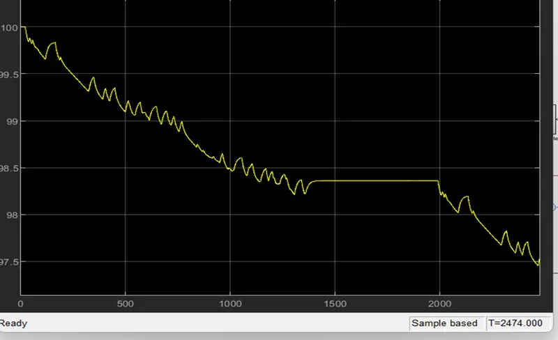
The above wave from shows the output of battery status of charge. We run simulation for FTP75 Drive cycle and for 2474 second the battery will consume 2.5% of the charge of battery.
- Output graph of drive cycle of FTP75 and output of vehicle
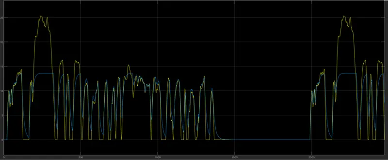
The above graph shows the yellow colour show the FTP75 drive cycle out put and blue colour shows the vehicle output.
3. output for H-bridge voltage and current:
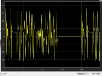
output current of H- bridge:
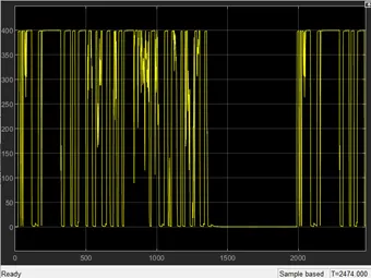
output voltage of H- bridge: