Final Project: Design of an Electric Vehicle
Create a MATLAB model of electric car which uses a battery and a DC motor. Choose suitable blocks from Powertrain block set. Prepare a report about your model including following:
Objectives:
1. System level configurations
2. Model parameters
3. Results
4. Conclusion
Answer :
Block Diagram of Electrical Vehicle
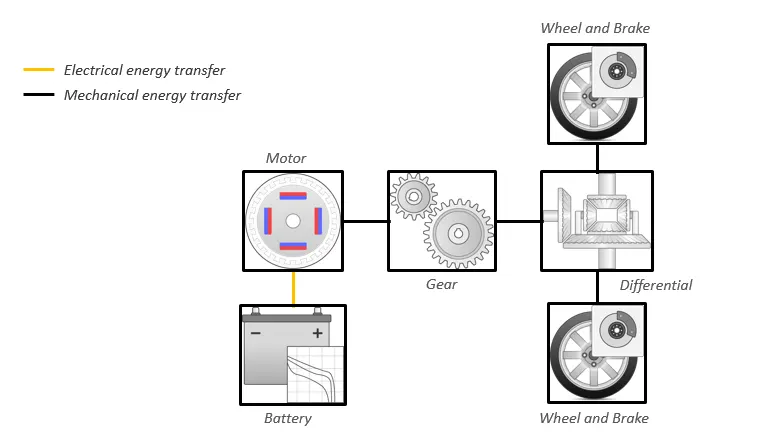
In Electrical Vehicle, Following Components are present:
- Battery
- Motor
- Gear
- Differentail
- Wheel and Brake
Detail View of Electrical Vehicle
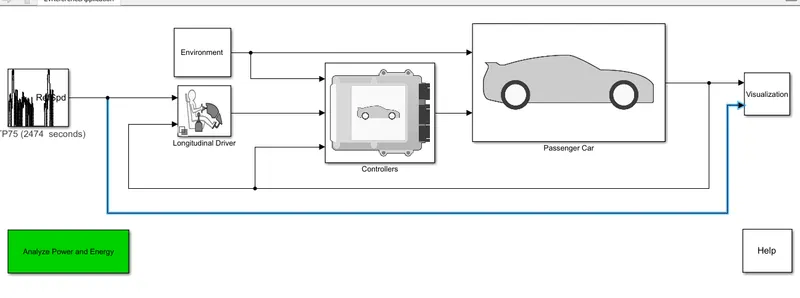
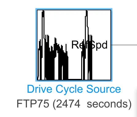
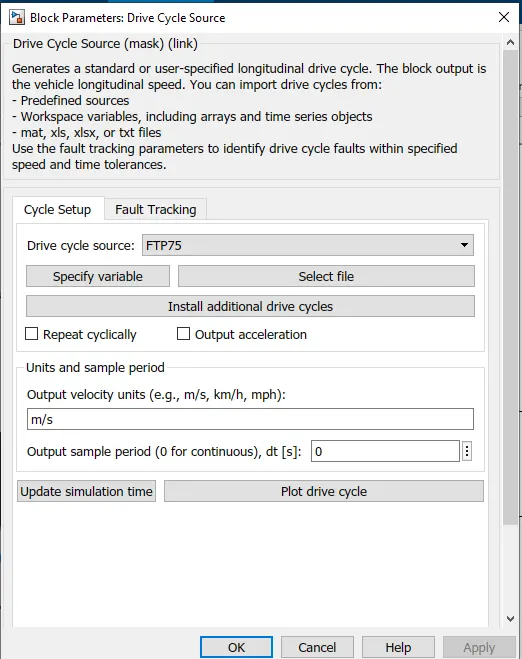
1) Drive Cycle Source:
The Drive Cycle Source block generates a target vehicle velocity for a selected or specified drive cycle. The reference application has these options.
| Timing | Variant | Description |
|---|---|---|
|
Output sample time |
|
Continuous operator commands |
|
|
Discrete operator commands |
Generates a standard or user-specified longitudinal drive cycle. The block output is the vehicle longitudinal speed. You can import drive cycles from:
- Predefined sources
- Workspace variables, including arrays and time series objects
- mat, xls, xlsx, or txt files
Use the fault tracking parameters to identify drive cycle faults within specified speed and time tolerances.
Controller :
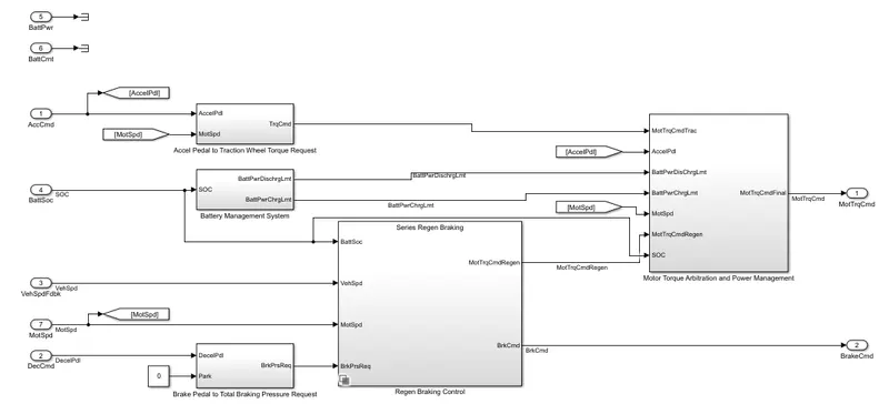
To determine the motor torque and brake pressure commands, the reference application implements a supervisory controller. Specifically, the controller subsystem includes a powertrain control module (PCM) with:
-
Regenerative braking control
-
Motor torque arbitration and power management
-
Converts the driver accelerator pedal signal to a torque request.
-
Converts the driver brake pedal signal to a brake pressure request. The algorithm multiplies the brake pedal signal by a maximum brake pressure.
-
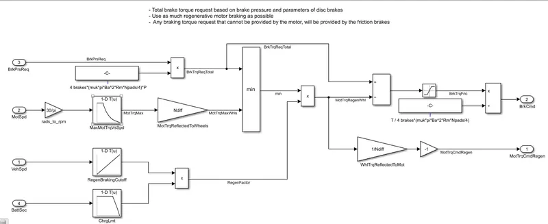
Implements a regenerative braking algorithm for the traction motor to recover the maximum amount of kinetic energy from the vehicle.
-
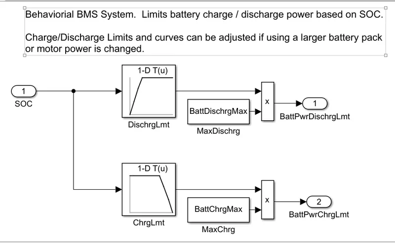
Implements a virtual battery management system. The algorithm outputs the dynamic discharge and charge power limits as functions of battery state of charge (SOC).
-
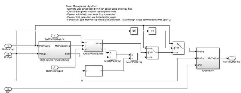
Implements a power management algorithm that ensures the battery dynamic discharge and charge power limits are not exceeded.
-
Regen Braking Control has these variants.
| Controller | Variant | Description |
|---|---|---|
|
Regen Braking Control |
Series Regen Brake (default) |
Friction braking provides the torque not supplied by regenerative motor braking. |
Parallel Regen Braking |
Friction braking and regenerative motor braking independently provide the torque. |
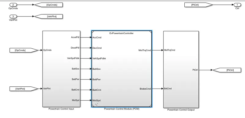
Powertrain Control Modulw(PCM):
Battery Management System:
Series Regeneration Braking :
Power Management:
Passenger Car
To implement a passenger car, the Passenger Car subsystem contains a drivetrain and electric plant subsystem. The reference application has these variants.
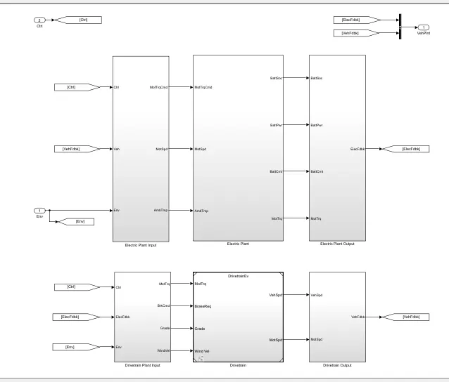
Drivetrain
| Drivetrain Subsystem | Variant | Description | |
|---|---|---|---|
|
Differential and Compliance |
All Wheel Drive |
Configure drivetrain for all wheel, front wheel, or rear wheel drive. For the all wheel drive variant, you can configure the type of coupling torque. |
|
Front Wheel Drive (default) |
|||
Rear Wheel Drive |
|||
|
Vehicle |
Vehicle Body 3 DOF Longitudinal |
Configured for 3 degrees of freedom |
|
|
Wheels and Brakes |
|
For the wheels, you can configure the type of:
For performance and clarity, to determine the longitudinal force of each wheel, the variants implement the Longitudinal Wheel block. To determine the total longitudinal force of all wheels acting on the axle, the variants use a scale factor to multiply the force of one wheel by the number of wheels on the axle. By using this approach to calculate the total force, the variants assume equal tire slip and loading at the front and rear axles, which is common for longitudinal powertrain studies. If this is not the case, for example when friction or loads differ on the left and right sides of the axles, use unique Longitudinal Wheel blocks to calculate independent forces. However, using unique blocks to model each wheel increases model complexity and computational cost. |
|
|
|
|||
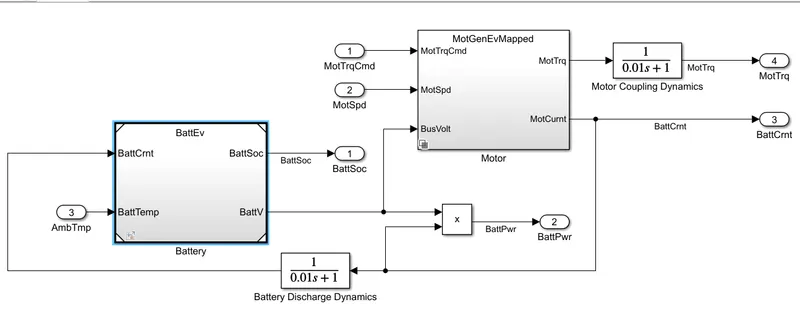
Electric Plant
| Electric Plant Subsystem | Variant | Description |
|---|---|---|
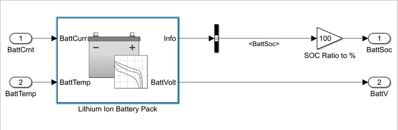
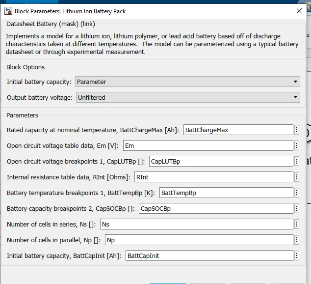
| Battery |
|
Configured with electric battery |
| Motor |
|
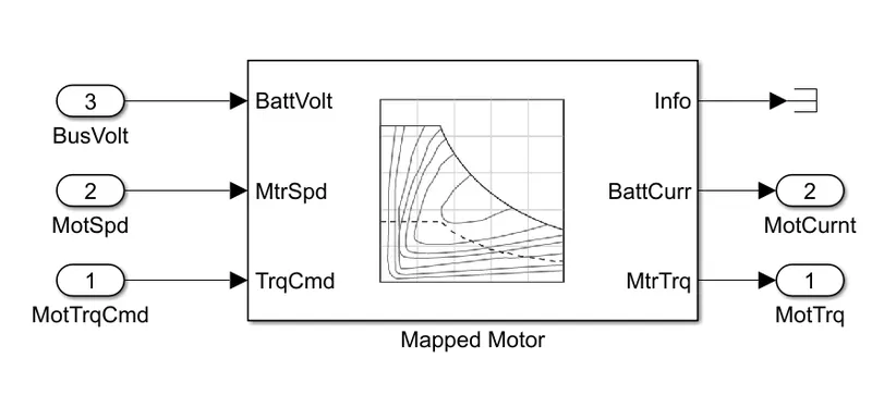
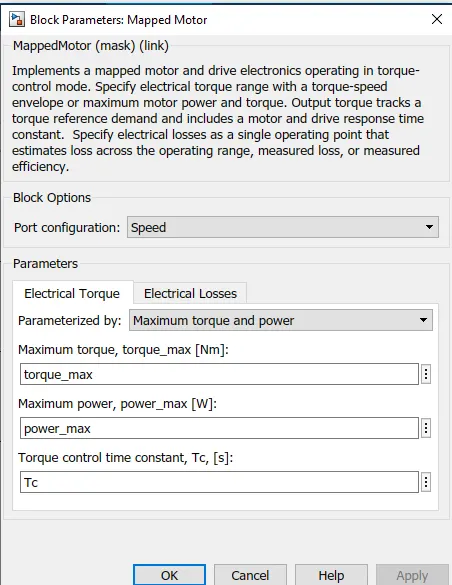
Mapped motor with implicit controller |
|
|
Interior permanent magnet synchronous motor (PMSM) with controller |
Longitudinal Driver
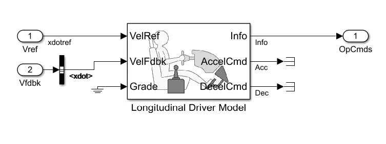
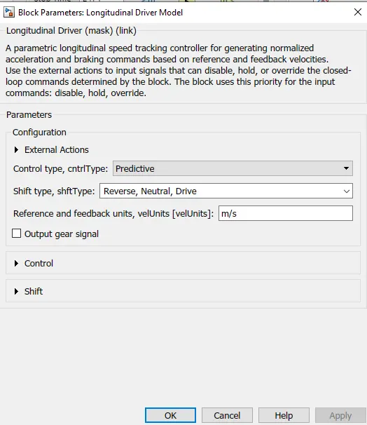
The Longitudinal Driver subsystem generates normalized acceleration and braking commands. The reference application has these variants.
|
Block Variants |
Description | ||
|---|---|---|---|
|
Longitudinal Driver (default) |
Control |
|
PI control with tracking windup and feed-forward gains that are a function of vehicle velocity. |
|
|
Optimal single-point preview (look ahead) control. |
||
|
|
Proportional-integral (PI) control with tracking windup and feed-forward gains. |
||
|
Low-pass filter (LPF) |
|
Use an LPF on target velocity error for smoother driving. |
|
|
|
Do not use a filter on velocity error. |
||
|
Shift |
|
Stateflow chart models reverse, neutral, and drive gear shift scheduling. |
|
|
|
Input gear, vehicle state, and velocity feedback generates acceleration and braking commands to track forward and reverse vehicle motion. |
||
|
|
No transmission. |
||
|
|
Stateflow chart models reverse, neutral, park, and N-speed gear shift scheduling. |
||
|
Open Loop |
Open-loop control subsystem. In the subsystem, you can configure the acceleration, deceleration, gear, and clutch commands with constant or signal-based inputs. |
||
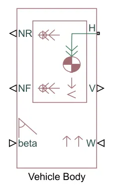
Vehicle Body:
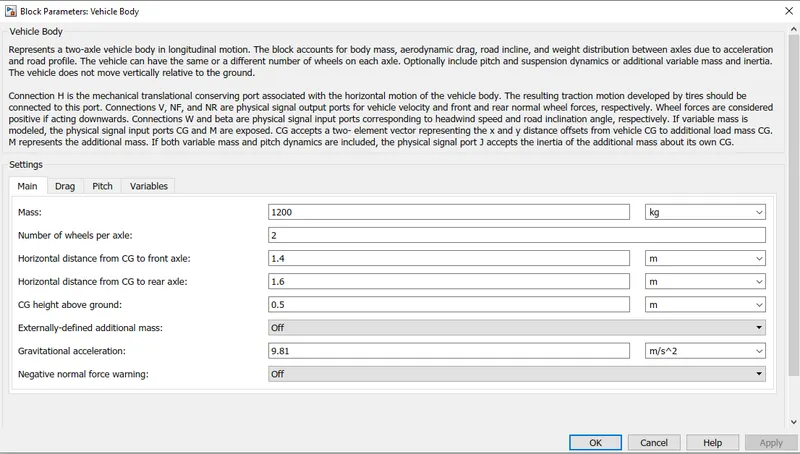
The Vehicle Body block represents a two-axle vehicle body in longitudinal motion. The vehicle can have the same or a different number of wheels on each axle. For example, two wheels on the front axle and one wheel on the rear axle. The vehicle wheels are assumed identical in size. The vehicle can also have a center of gravity (CG) that is at or below the plane of travel.
The block accounts for body mass, aerodynamic drag, road incline, and weight distribution between axles due to acceleration and road profile. Optionally include pitch and suspension dynamics. The vehicle does not move vertically relative to the ground.
The block has an option to include an externally-defined mass and an externally-defined inertia. The mass, inertia, and center of gravity of the vehicle body can vary over the course of simulation in response to system changes.