Final Project: Design of an Electric Vehicle
Final Project: Design of an Electric Vehicle
Aim: Create a MATLAB model of electric car which uses a battery and a DC motor. Choose suitable blocks from Powertrain block set. Prepare a report about your model including following:
Objectives:
1. System level configurations
2. Model parameters
3. Results
4. Conclusion
Theory:
Electric Vehicle:
An electric vehicle (EV) is a vehicle that uses one or more electric motors for propulsion. It can be powered by a collector system, with electricity from extravehicular sources, or it can be powered autonomously by a battery (sometimes charged by solar panels, or by converting fuel to electricity using fuel cells or a generator).[1] EVs include, but are not limited to, road and rail vehicles, surface and underwater vessels, electric aircraft and electric spacecraft.
Modeled EV:
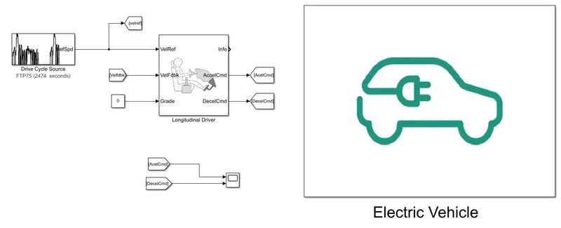
Components Inside EV:
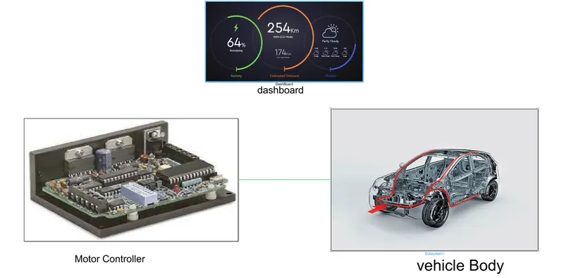
Motor and Motor Controller:
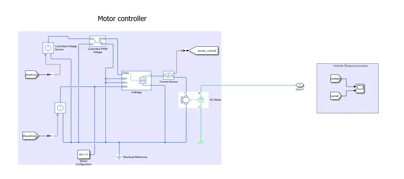
System Parameters:
Controlled PWM Voltage Block:
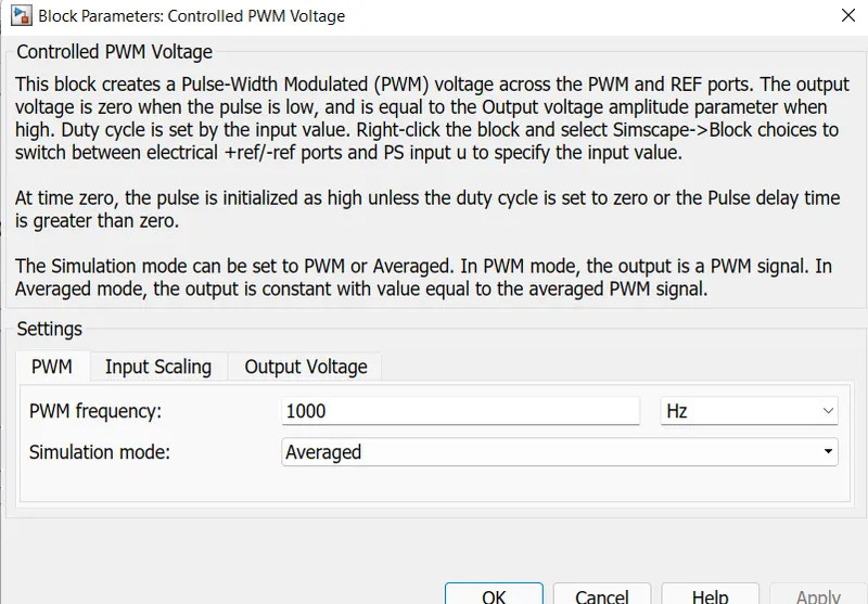
Input scaling :
Input voltage for 0% duty cycle: 0
Input voltage for 100% duty cycle: 1
Output Voltage:
Output voltage amplitude : 1
Accelerator is connected to this block.
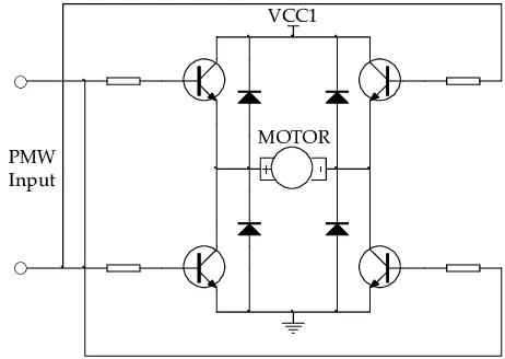
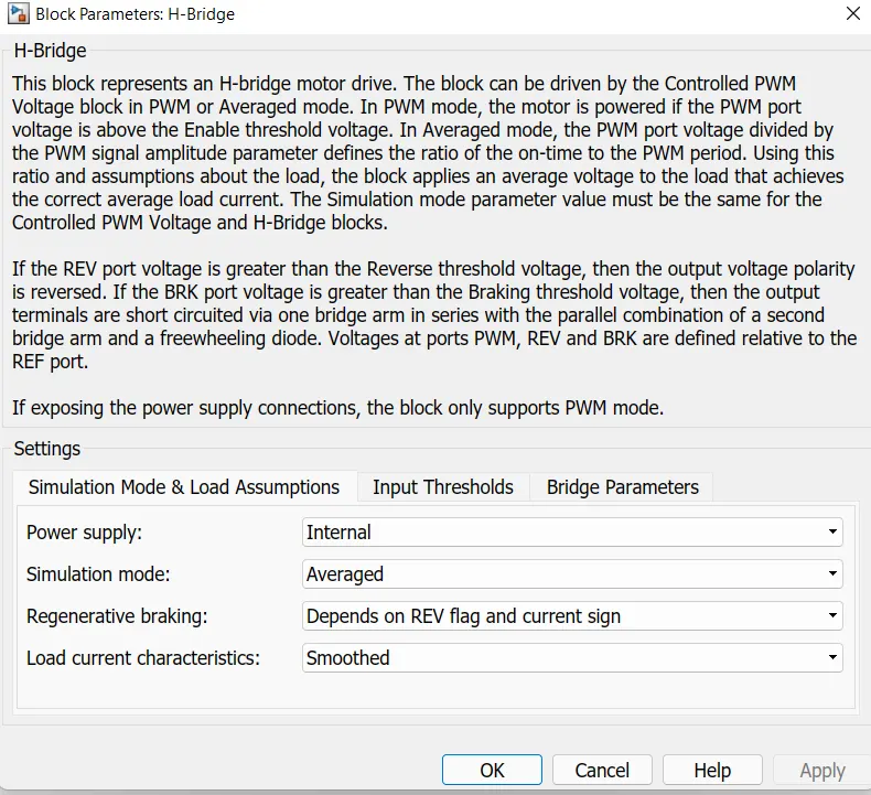
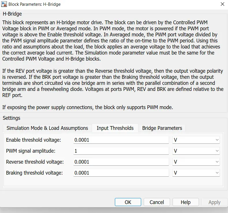
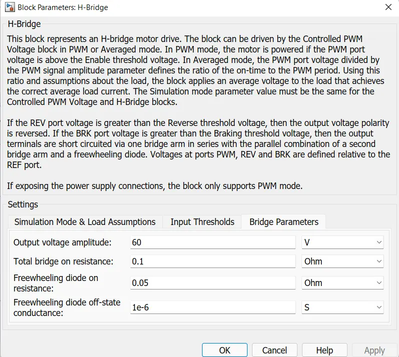
H-Bridge:
The H-bridge is an electronic circuit that looks like the letter H. An H-bridge is used to drive a load, such as a brushed DC motor, in both directions. And it controls the flow of current to a load.
Simulation Mode and Load assumptions:
Input Thersholds:
Bridge Parameters:
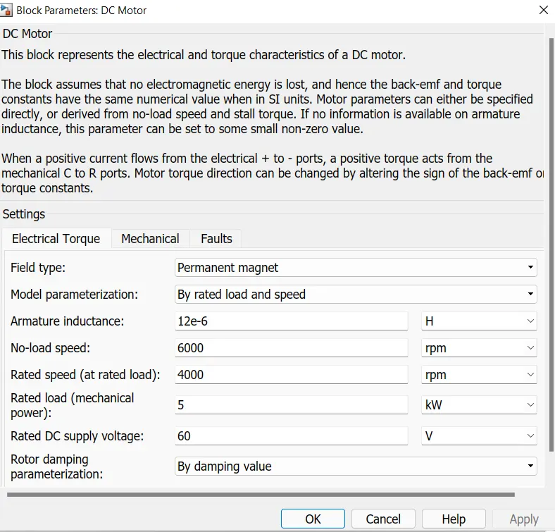
DC motor:
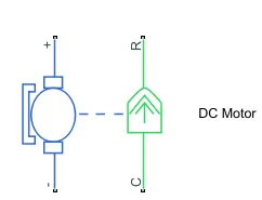
Blue portion in block is where electrical connections are made, Green portion is mechanical part of the motor, it has four connection ports two are for power supply connections and port R is rotating object and port C is casing part of motor which is connected to rotational reference.
Block Configration:
Vehicle Body and Transmission Block:
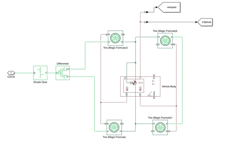
Components:
1.Simple Gear
2.Differential Gear
3.Tire
4.Vehicle Body
1.Simple Gear:
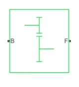
Here this is an simple where the Driving shaft comes from motor and joins at B port and driven shaft is connected at F port.
Here all the losses like meshing losses and viscous losses are neglected.
Block parameters:
Gear ratio : 2
Output shaft rotates : Same direction as Input shaft
2.Tire:
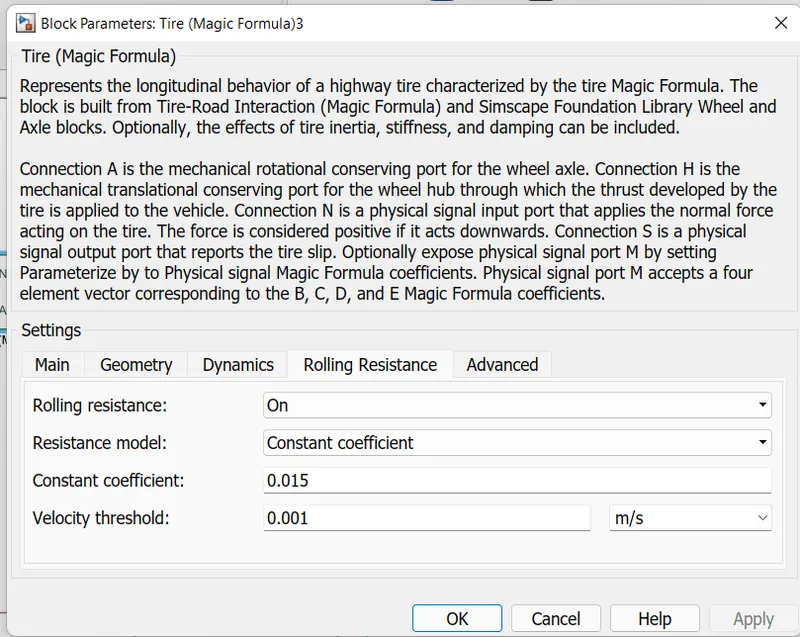
Represents the longitudinal behavior of a highway tire characterized by the tire Magic Formula. The block is built from Tire-Road Interaction (Magic Formula) and Simscape Foundation Library Wheel and Axle blocks. Optionally, the effects of tire inertia, stiffness, and damping can be included.
1.Connection A is the mechanical rotational conserving port for the wheel axle.
2.Connection H is the mechanical translational conserving port for the wheel hub through which the thrust developed by the tire is applied to the vehicle.
3.Connection N is a physical signal input port that applies the normal force acting on the tire. The force is considered positive if it acts downwards.
4.Connection S is a physical signal output port that reports the tire slip.
Block Parameters:
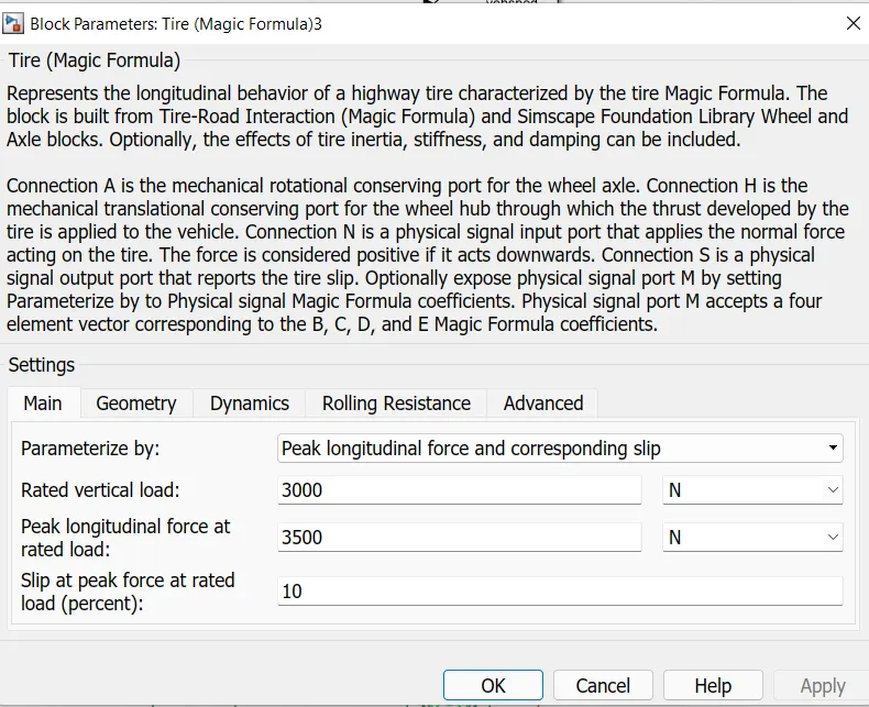
Wheel Diameter : 0.3 m
Vehicle Body:
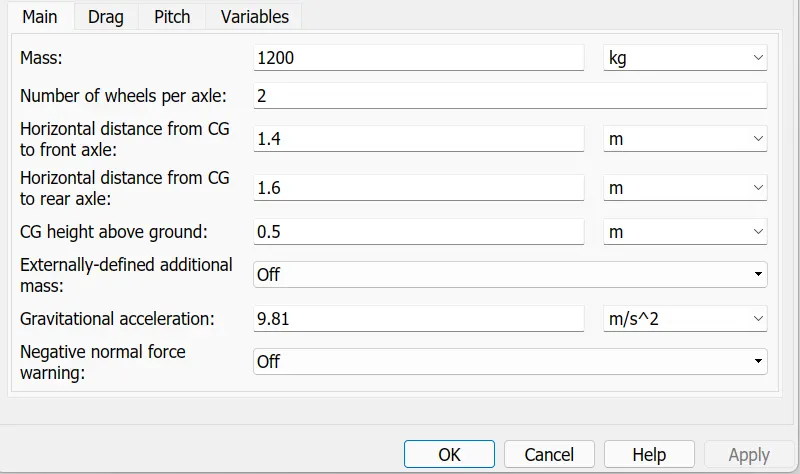
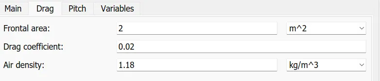
Represents a two-axle vehicle body in longitudinal motion. The block accounts for body mass, aerodynamic drag, road incline, and weight distribution between axles due to acceleration and road profile. The vehicle can have the same or a different number of wheels on each axle. Optionally include pitch and suspension dynamics or additional variable mass and inertia. The vehicle does not move vertically relative to the ground.
1.Connection H is the mechanical translational conserving port associated with the horizontal motion of the vehicle body. The resulting traction motion developed by tires should be connected to this port.
2.Connections V, NF, and NR are physical signal output ports for vehicle velocity and front and rear normal wheel forces, respectively. Wheel forces are considered positive if acting downwards. Connections W and beta are physical signal input ports corresponding to headwind speed and road inclination angle, respectively.
Results:
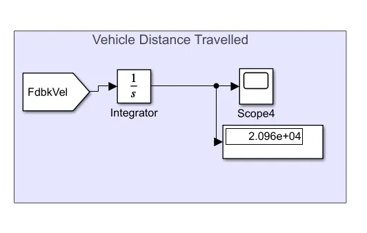
1. Drive Cycle source FTP75 is used as drive cycle, Simulation was ran for 500 Seconds the results are below.
Distance Travelled in 500 Secs:
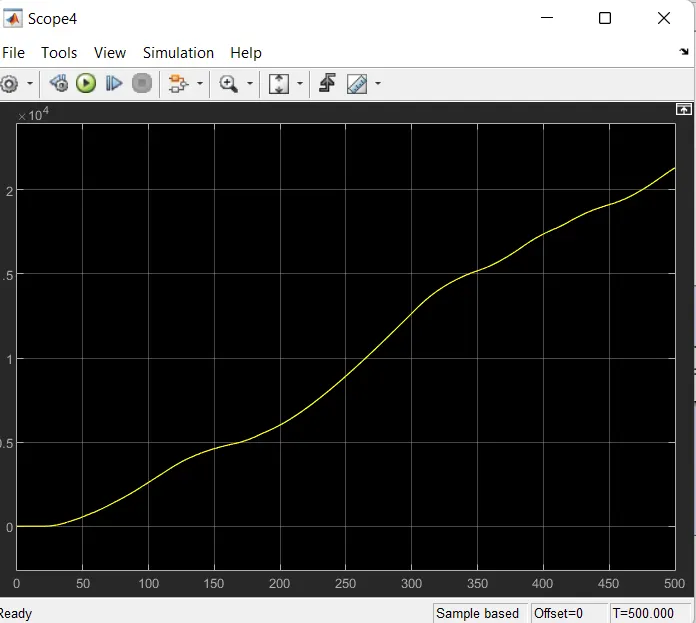
Distance Travelled around 2.1 kms
2. State Of Charge:
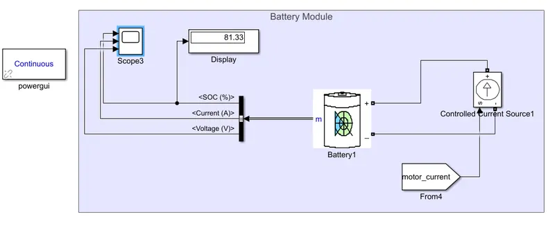
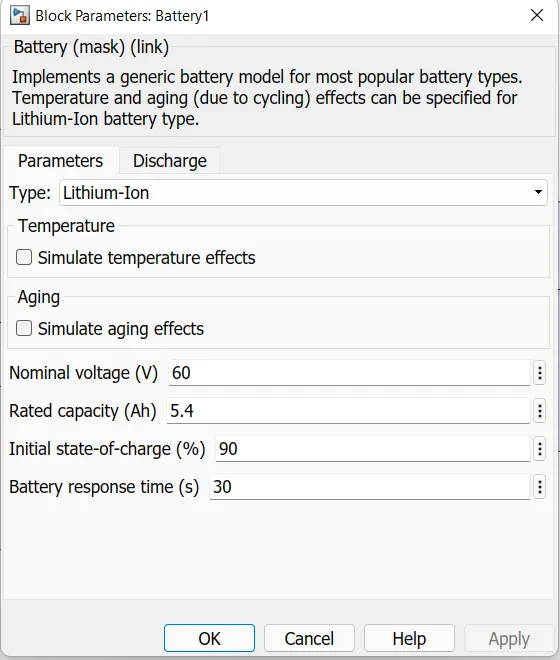
Here a battery of lithium ion is taken with following parameters:
After simulating for 500 seconds below are the battery state of charge.
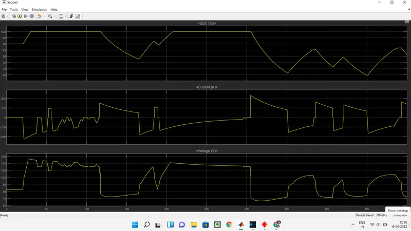
Here the battery is charged with back emf produced during braking, there is also change in direction of current while braking which indicates the reversal flowof current.
3.Difference between Reference velocity and Feed back velocity:
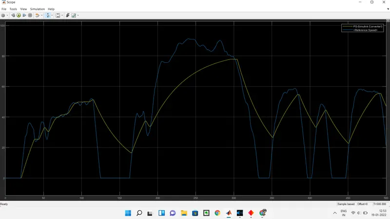
The yellow line represents feed back velocity i.e vehicle velocity and blue line is reference velocity.
There is a variation in both the velocities as, The battery capacity isnt good enough to propell the motor so vehicle could reach required speed.
Conclucion:
Electic vehicle model has been sucessfully modelled and using drive cycle source the model has been tested and results are discussed.