Final Project: Design of an Electric Vehicle
Introduction to HEV using MATLAB & Simulink
Final Project: Design of an Electric Vehicle
Aim:
Create a MATLAB model of electric car which uses lithium ion battery and induction motor. Choose suitable blocks from Powertrain block set.
Prepare a report about your model including following:
Objectives:
1. System level configurations
2. Model parameters
3. Results
4. Conclusion
Ans=>
- Introduction :
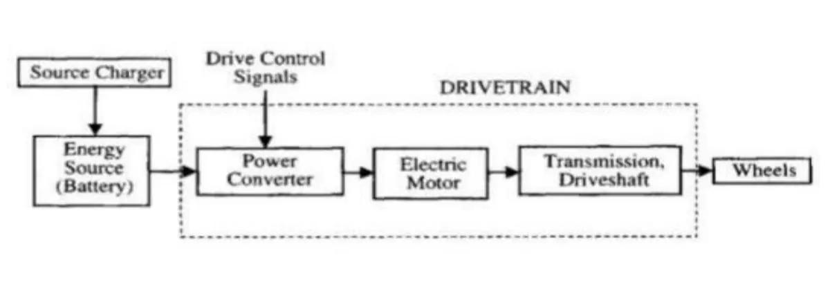
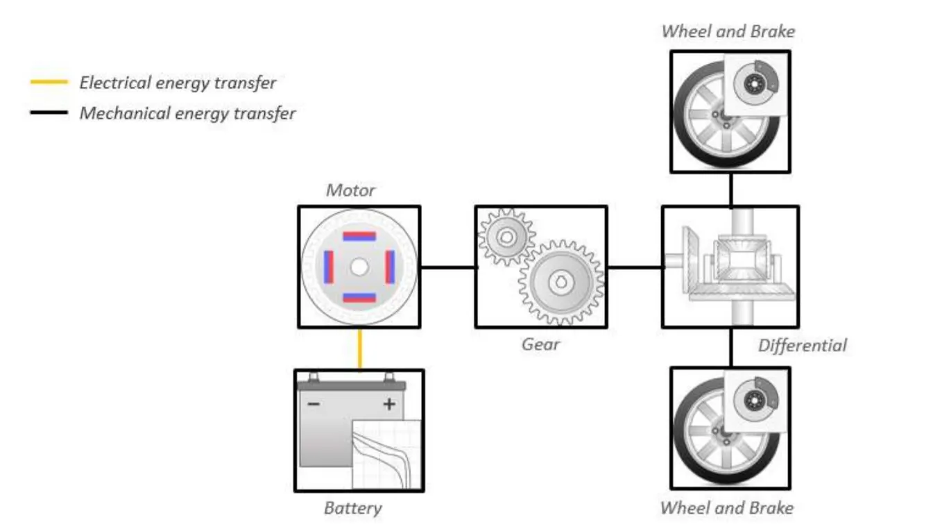
Battery Electric Vehicles (BEVs), compared to classic internal combustion engine (ICE) vehicles, are fairly simple and easy to operate. The simplest powertrain architecture consists in a high voltage battery, an electric motor with power electronics controller and a single speed gearbox. BEVs are also called pure electric vehicles.
In a BEV the propulsion is based exclusively on the electric energy stored in the high voltage battery.
Battery electric vehicle are increasing their market share because they are the most viable way towards a clean and efficient transport system. Compared with ICE vehicles, the most important advantages of a BEV is the overall high efficiency, reliability and relatively low cost of the electric motor. The main drawback is the low energy density of the high voltage battery.
Pure Electric Powertrain:
Archittecture of Electric Vehicle
- System Level Configuration:
There are major components which is using in EV
1. Drive Cycle
2. Driver
3. H-Bridge
4. DC Motor
5. Battery Source
6. Controlled PWM Voltage
7. Vehicle and others
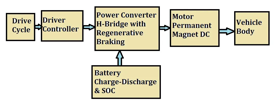
- Block Diagram
- EV Model
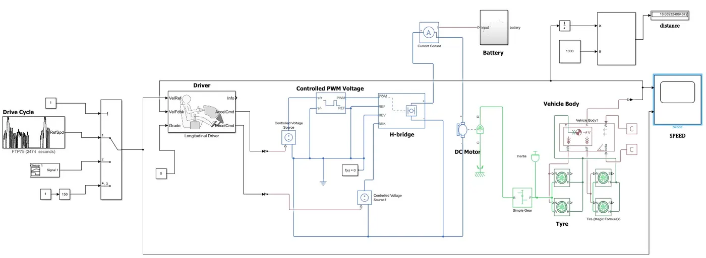
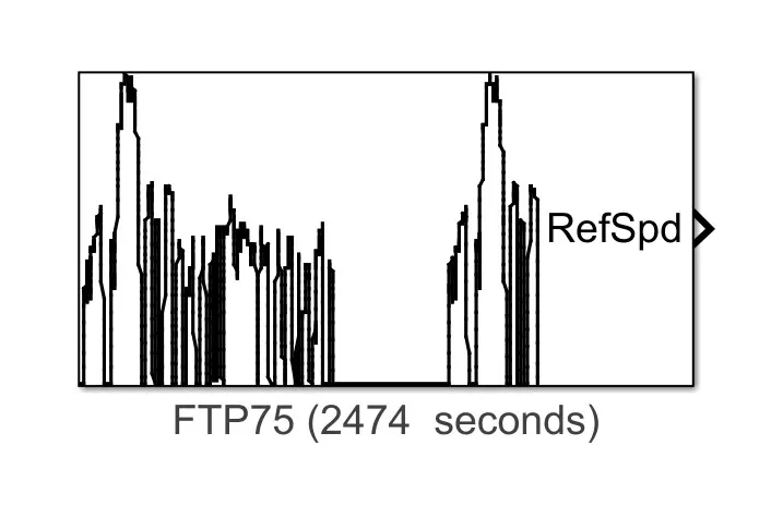
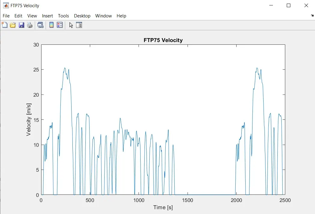
Starting with the Drive Cycle, We have chosed the FTP75 Drive Cycle for the operation of the Cycle in which the test duration would 2474 seconds.
- 1. Drive Cycle
- 2. Driver Model
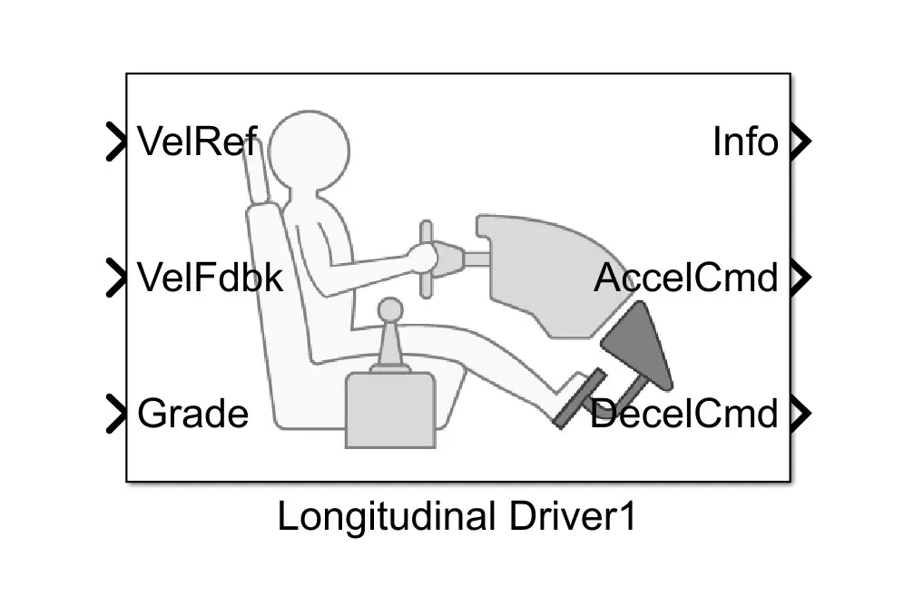
The Driver model has the input ports which are connected to the following
Velocity Reference - Drive Cycle
Velocity Feedback - Connected to vehicle Body Speed Calculation act as close loop feedback to meet desire speed as per reference input
Grade - Constant 0
Info - Not Connected
Acceleration Command - Connected to Controlled PWM Source through which it is conected to Controlled PWM Voltage to vary duty cycle according to drivers input.
Deceleration Command - Connected to Brake in of H-Bridge to maintain the speed according to the Drive Cycle and deccelerate the vehicle.
The parameters inputs are as follows :
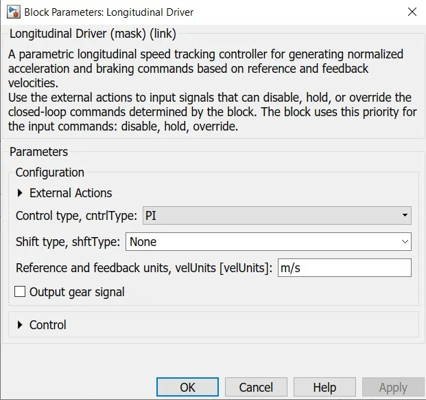
PI Control Type is selected (Proportional Integral). This is nothing but Throttle pedal of the driver which will try to match the with input drive cycle given and according to it PI controller will try to match whether acceleration or decceleration as per input given.
- 3. H-Bridge
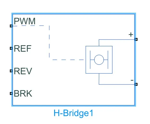
The H-Bridge helps in controlling the power that is input according to the requirement. The output provided are converted voltage as per the controlled parameters.
The Ports for Input and Output are PWM - Pulse Width Modulation
REF - Controlling with Reference
REV - Controlling with Reverse
BRK - Controlling the Brake and Regenerative
+ = Controlled Output to the positive Terminal of the Motor
- = Cotrolled Output to the Negative Terminal of the Motor
Parameters Consider for the H-Bridge
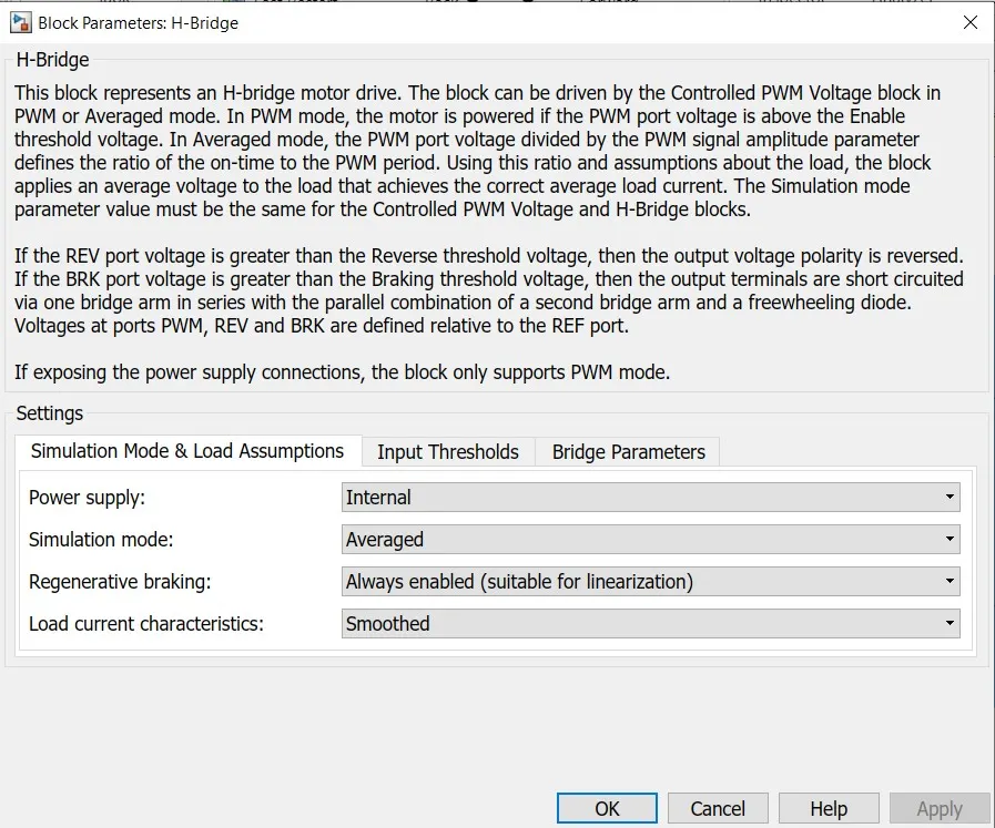
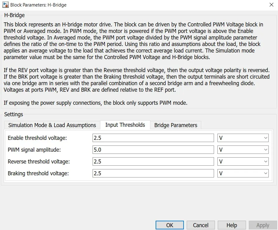
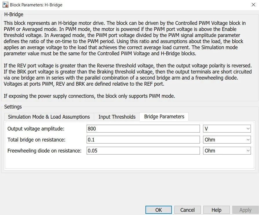
We have selected the Internal type Power Supply and Enabled the Regenerative Braking for flow power back to battery while braking and decceleration to make EV efficient.
- 4. DC Motor
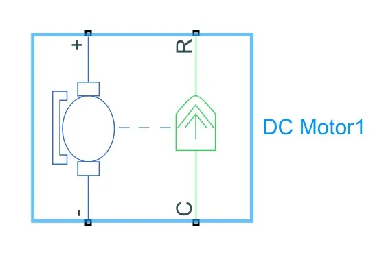
This is the DC Motor (Brushed Type) Terminals are connected as mentioned below-
+ = Electrical Signal to the Motor Positive Terminals
- = Electrical Signal to the Motor Negative Terminals
C = Connected to Casing of the Motor connected with the Mechanical Rotational Reference Block
R = Rotor shaft of dc motor is connected to simple gear vary torque and speed
The Parameters consider are
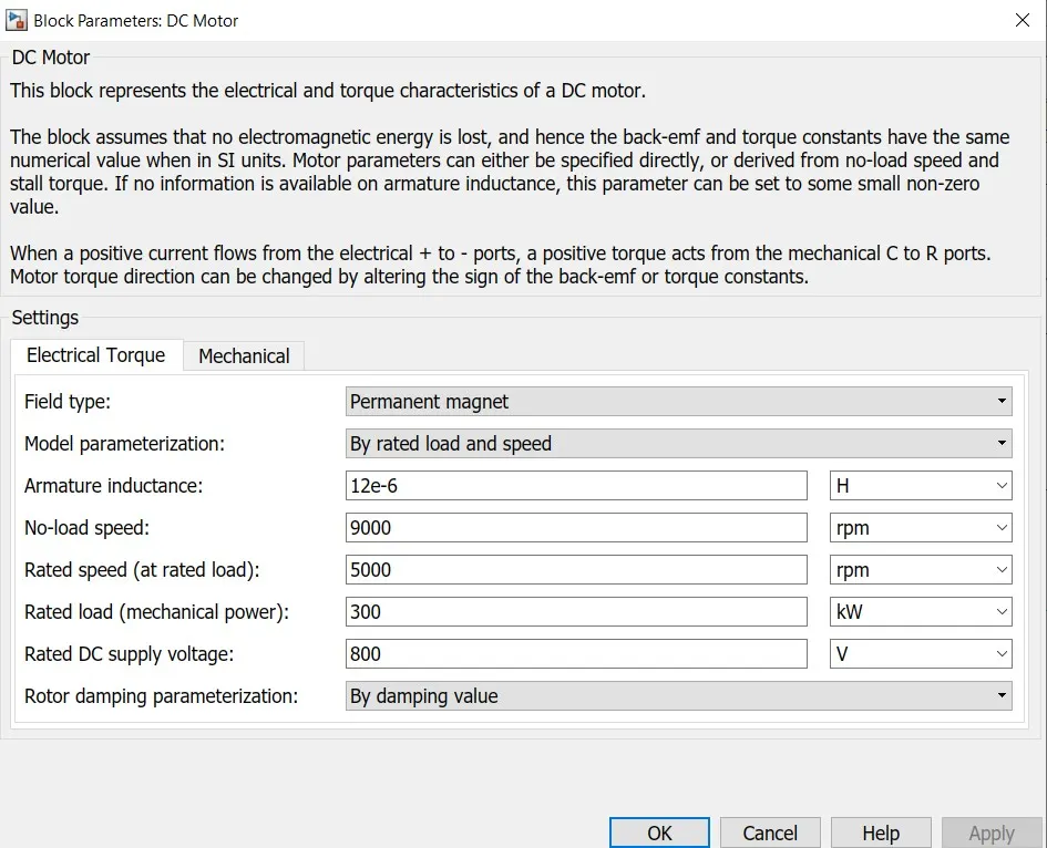
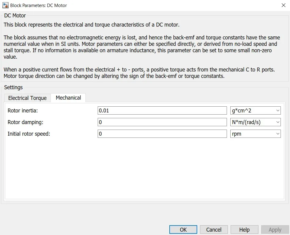
Field Type is Permanent Magnet.Model Parameterized by rated Load and speed.The Armature Inductance is as default, We have varied the changes in the No-load Speed @ 9000 RMP, the rated speed @ 5000RPM, the Rated Load (Mechanical Power) at 300 KW, and the Rated DC Supply Voltage @ 800V. All other parameters are as default.
- 5. Battery Source
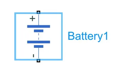
The Battery is connected as the source to the model so that the power could be genereted and the same power is transmitted accordingly to all the operating sources and load demand of driver.The Terminals connected are to,
+ = The Positive Terminal of the operating sources
- = The Negative Terminal of the operating sources
The Complete Battery Block
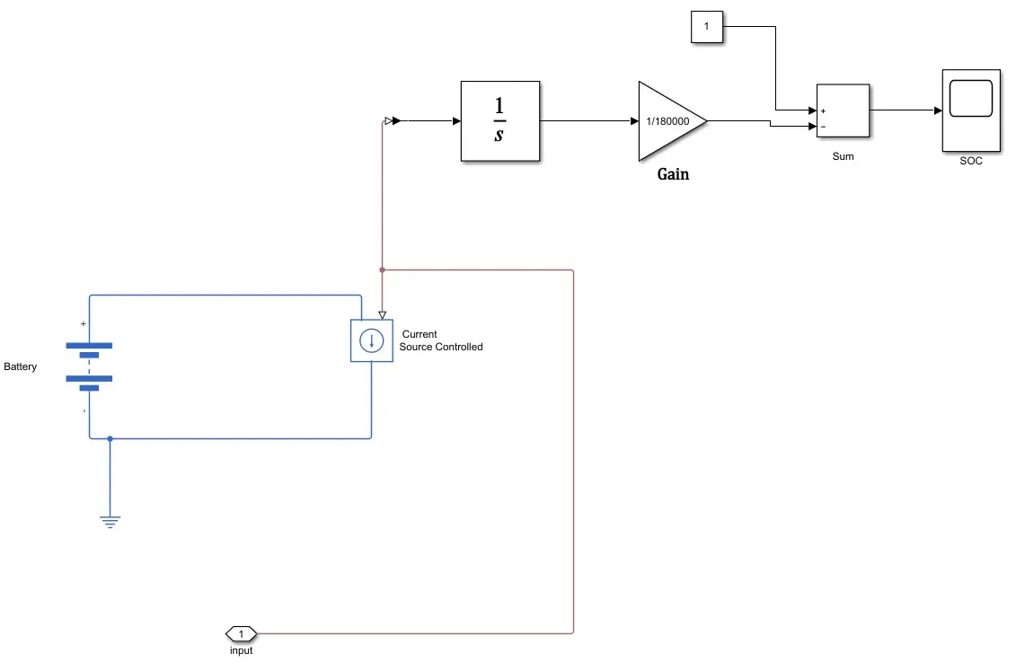
The complete block is as mentioned above it includes the controlled current sources to draw controlled current from battery to load, the electrical reference, PS-Simulink Converters, the Scope and the SOC Estimate.
SOC Estimation :
For SOC estimation we use simple method called Coulomb Counting.
Coulomb counting is a technique used to track the State of Charge of a battery pack. It works by integrating the active flowing current (measured in amps) over time to derive the total sum of energy entering or leaving the battery pack. This produces a capacity that is typically measured in Amp-hours.
The SOC Estimate Block is connected with battery through Controlled Current Source block from which Integrator block counts all time period values of +,- values of current, the Gain considered at (1/50*3600) Ah capacity of battery, the sum block subtract the SOC from Initial set Constant block . This gives us the Battery SOC Estimate.
The parameters considered of the Battery are
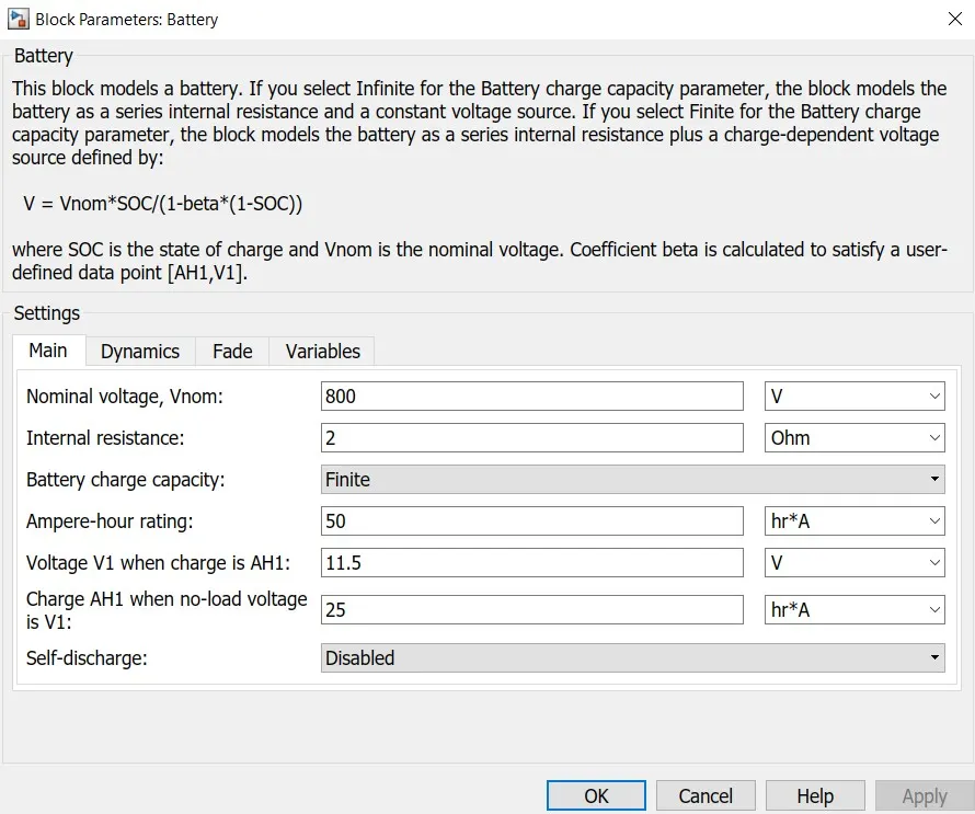
The Battery Nominal Voltage is rated as per 800 Volts, the internal resistance is as per 2 Ohm, Battery charge capacity 50 Ah (finite) and rest all others are as default
- 6. Controlled PWM Voltage
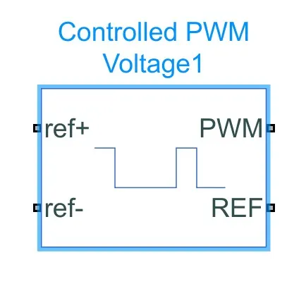
Controlled PWM Voltage to vary duty cycle according to drivers input.
The Controlled PWM Voltage Block helps in keeping the Modulated Pulses as per the required pulses. So that the operations happens smooth and higher variations are not observed.The ports are connected as follows
ref+ = Reference Positive connected with the Acceleration Commands from the Driver Model
ref- = Reference Negative connected with the Deceleration Commands from the Driver Model
PWM = PWM connected directly to the H-Block
REF = REF connected directly to the H-Block
The parameters are as follows
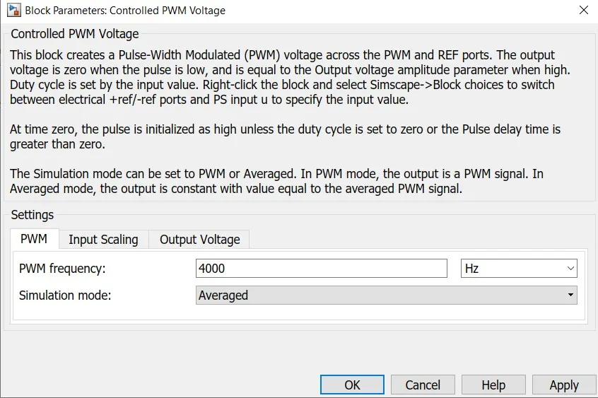
To have less simulation time we selected as Average instead of PWM Simulation mode.PWM frequency is set @ 4000 Hz to make operation smooth & fast, rest all set as default.
- 7. Vehicle
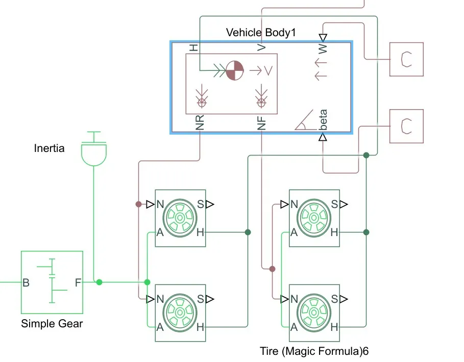
The Component in the Block are the
1. Simpe Gear - For engaging the correct gear at the right duration where required.
2. Tyre - 4 Tyre and the Operational wheels are the Rear, as the vehicle represented here Rear Wheel Drive.
3. Vehicle Block - Specifications of the same are mentioned below.
4. Angle - The Angle could be as the road condition the slope at which the car is running.
5. Wind - The Wind could be specified as per the condition where the vehicle has to be driven.
6. Velocity - The Speed of the EV CAR.
7. NF - The Front Wheel Connection.
8. NR - The Rear Wheel Connection.
The detailed parameters are as follows
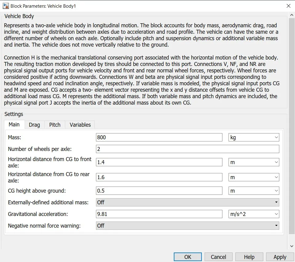
Mass of vehicle set to 800kg while rest all others are as default.
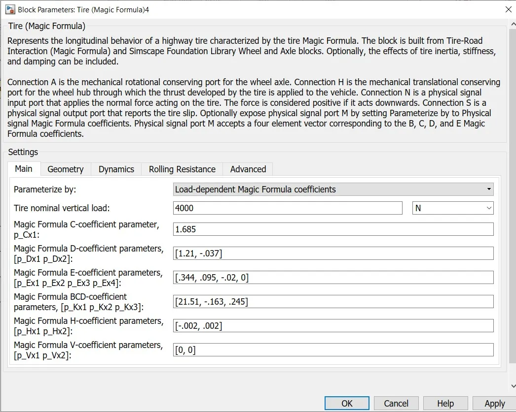
Here, Tire parameterize by : Load-dependent Magic Formula coefficient,
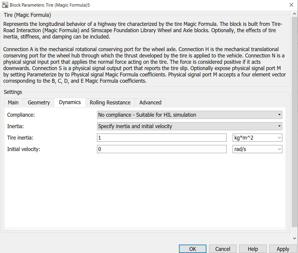
Here we set Inertia as Specify inertia and initial velocity
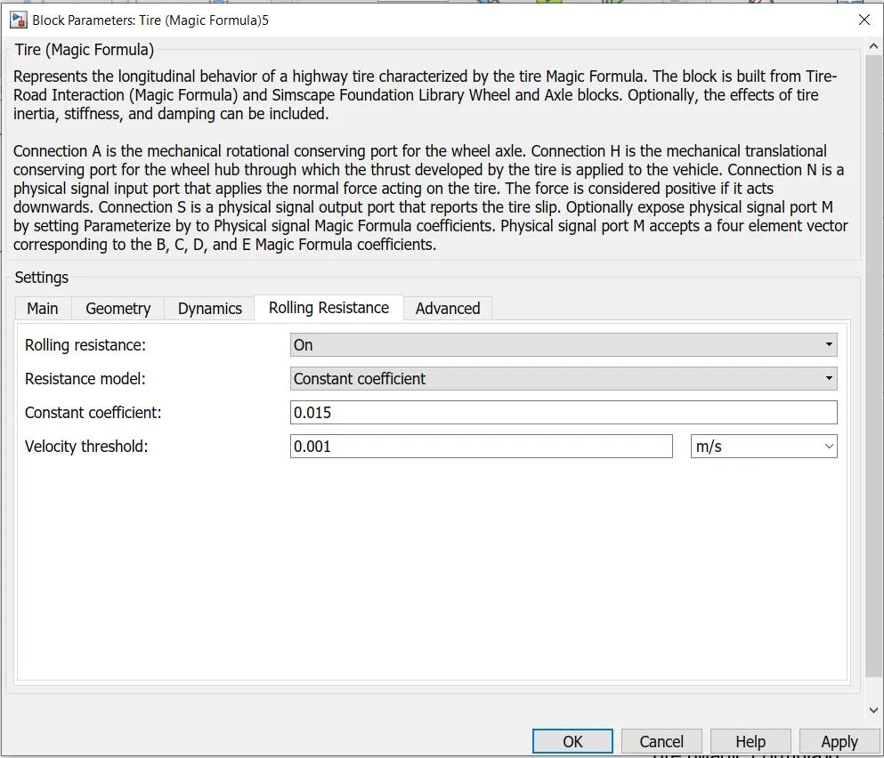
and set Rolling resistance On and rest all values as default.
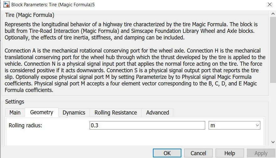
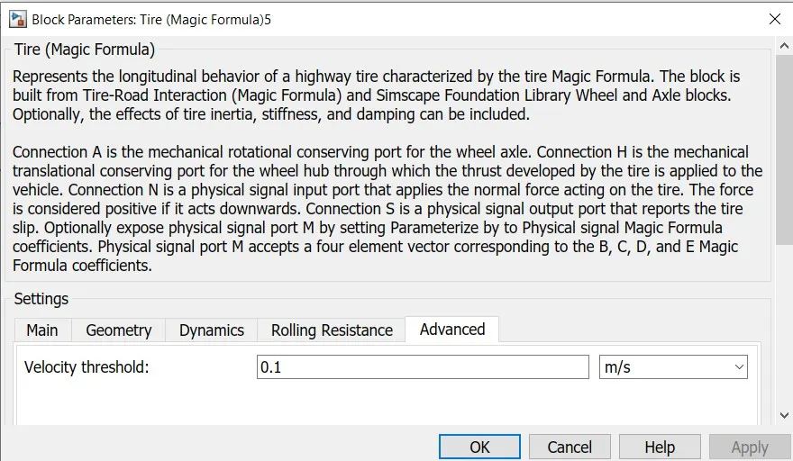
These are the model details which would be simulated and the results are as follows:
- Scope 1 - The Velocity Feedback and the Drive Cycle Source
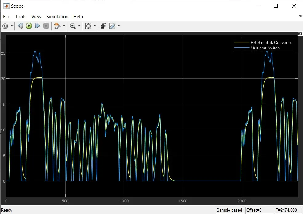
Here results are according values selected as above detail parameters.Max speed achieve is 20m/s but not max speed of drive cycle.So now we again increase the motor rating and see the result as follows.
- Scope 2 - The Velocity Feedback and the Drive Cycle Source with increase Motor rating
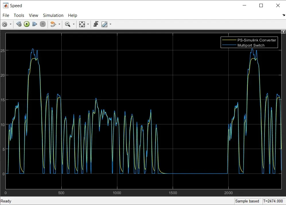
Here we have set Motor Mechanical power @800KW & Rated DC supply @ 800V .Thus we can see like vehicle nearly matches with max speed of drive cycle input given. To match further we need to increase motor rating further.
- Scope 3 - The Velocity Feedback and the Drive Cycle Source with increase Motor rating
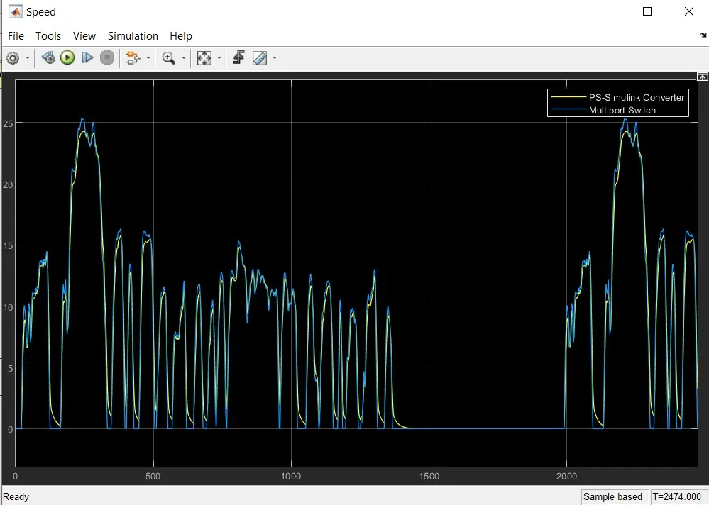
Here we have set Motor Mechanical power @1000KW & Rated DC supply @ 1000V .Which is practically far high rating for DC type Motor.But with this change in simulink environment we can see like , vehicle almost matches with max speed 25m/s of drive cycle input given.
- Here PS Simulink converter (Yellow line) is our Vehicle speed output and Multiport switch (Blue line) is input given as drive cycle (FTP75) which vehicle tries to match with input drive cycle with EV model and its parameters.
Thus from above result, we can see that Vehicle speed output almost matches with reference speed input with small deviation due to vehicle inertia and its control parameter.
The Vehicle is operated as per the Battery specifications as mentioned above on the specifications, the battery voltage supplied as the major source is 800V and the motor used is the DC Motor which tries to operate the vehicle as per drive cycle input given.
The overall distance travelled by the vehicle 18 kms in a duration of 2474 seconds.
- Battery SOC Scope 4-
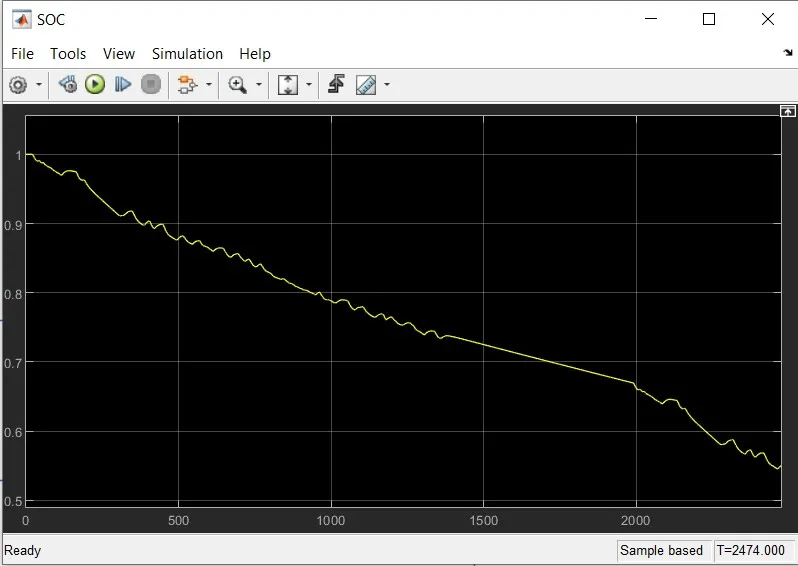
It is noted that the charge of the battery started from 100% at the initial level and during the operation of the vehicle for 2474 seconds using the FTP75 Drive cycle.
Battery got discharge nearly to 50% and after the acceleration was been released the battery started recharging as the Regeneretive
In between while vehicle deccelerating and while braking battery started recharging beacause during this time duration Motor act as Generator and flow negative current back to battery .This can be seen from above result like sometimes SOC (State Of Charge) spike starts increase.
- CONCLUSION:
It is clearly visible that the vehicle could be simulated in the same manner and different such simulations could be made to analyze.
These same simulations could be carried out before deciding the overall specification that the vehicle should achieve. In this manner the motor , Battery and other components could be chosen and then the actual model could be manufactured.
There are chance of varition in the results which would be obtained in comparison of the actual and MATLAB Simulations as actual Conditons would vary the results.
All components could be customized as per the test which has to be carried out like the vehicle mass, the Vehicle Battery Specification the Battery motor and all others.
As we analyzed in the test carried out above the vehicle has successfully achived the max speed of 20m/s but could not achieve max speed of drive cycle 25 m/s in Scope-1, due to DC motor limitation as we have selected field type as Permanent Magnet. So voltage is applied to armature of Rotor to magnetised PM of rotor and if we select both Stator and Rotor to Supply Voltage then magnetisation power will be more and rotor will rotate with less amount of current and less amount of voltage to match desired speed.
As we can see the Scope-2 & Scope-3 , Vehicle can successfully achieved the max speed of 25 m/s by increasing the Motor power (KW) and Voltage(V) respectively.