Final Project: Design of an Electric Vehicle
Design of an Electric Vehicle
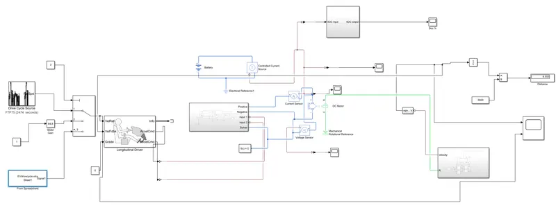
Create a MATLAB model of electric car which uses a battery and a DC motor. Choose suitable blocks from Powertrain block set. Prepare a report about your model including following:
Objectives:
1. System level configurations
2. Model parameters
3. Results
4. Conclusion
Electric Vehicle :
The main work of vehicle is to move people,goods or anything we want from one place to another place.we can do this work by many option ike we can use of animals,use of boat,plane,train and vehicle.in vehicle we can use two wheeler,three wheeler, four wheeler, trucks,crains,etc...and these vehicle are conventional like they use petrol,diesel fossil fuel,some are using gas(LPG,CNG,etc),but its harmfull for environment and it will create pollutonlike Air aswell noice pollution.so what i am trying to say is we just need to go one to another direction so why we cant use that things which is pollution free,have a enough speed,less cost,high torque,and human friendly.so for that we can add electric vehicle in this list.apart from this we can use HEV(hybrid electric vehicle),fuel cell vehicle by using hydrogen as fuel cell,ethanol based vehicle and in future we can find many options aswell.
An electric vehicle (EV) is defined as a vehicle that uses an electric motor or a traction motor for propulsion as opposed to an internal combustion (IC) engine used by conventional vehicles. Electric vehicles use electricity for power instead of fossil fuels as conventional vehicles would and because of this difference, electric vehicles do not produce any exhaust gases or pollution. The power needed for the operation of an EV can come from a variety of sources such as batteries, generators, or through a collector system. Batteries fitted in to the body of an EV are capable of high energy densities in order for them to meet the power demands and range requirements. Generators are machines which generate electrical energy from an input of mechanical work and are a part of the electric motor, and they operate during braking to produce the phenomenon of regenerative braking. Collector systems are off-vehicle systems which allow for the charging of an EV from homes or public charging stations. The electricity used for charging in these systems are generated from solar panels which can be used by the grid or by homes of EV owners so that they can charge their vehicles more conveniently.
EVs offer several advantages over conventional vehicles besides the lack of pollution and lack of need to rely on fossil fuels. One is that, EVs are more efficient meaning that they offer more miles per gallon gasoline equivalent, meaning that you will spend lesser on recharging an EV than you would to refuel a conventional vehicle. This because the more efficient the EV is, the more distance you travel with the available energy. In the US, Tesla owners can charge their EVs for free at their private charging stations for life which results in significant savings in fuel. Regenerative braking in EVs adds to their efficiency as the unused energy in braking gets reused purposefully. Another benefit is that EVs have fewer moving/rotating parts and this means lesser maintenance costs than you would have with IC engine vehicles e.g. changing oil, transmission fluid. This, in the long term would give better savings than you would get with conventional vehicles. Lesser moving parts means there is lesser friction between moving parts and hence quieter operation.
A compromise between IC engine vehicles and EVs exists as Hybrid Electric Vehicles. HEVs combine an IC engine with an electric propulsion system to produce a 'hybrid' between the two different classes of vehicles. The purpose of this is to use the power available form the electric powertrain to improve the fuel economy of the vehicle so that it does not rely solely on the petrol/diesel it uses as fuel. This in turn will also improve the overall performance of the HEV. The IC engine can be used to power the electric motor to charge the battery or use directly in the electric drive motor with a combination of a motor and generator in one. HEVs also implement regenerative braking to recharge their batteries among other features used in EVs. Compared to EVs, HEVs represent more of the automotive market with a 19% market share on all automobiles in the world. This is because HEVs still run on fossil fuels which is still more convenient as a fuel source in most parts of the world. The all time best selling HEV to date is the Toyota Prius.
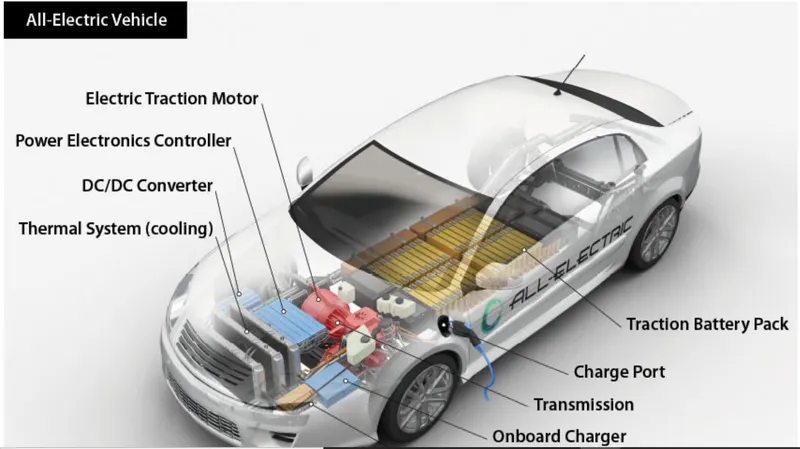
The main components of an electric vehicle are:
- Battery (auxiliary)
- Electric traction motor
- Onboard charger
- Thermal system (cooling)
- Power electronics controller
- Inverter(in case of AC motor)
- Charge port
- Transmission
- DC to DC converter
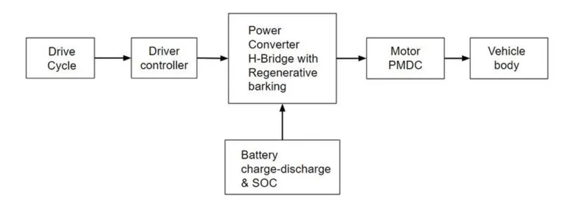
Block Diagram of the Electric Vehicle shown below:
PROCEDURE :
MODEL :
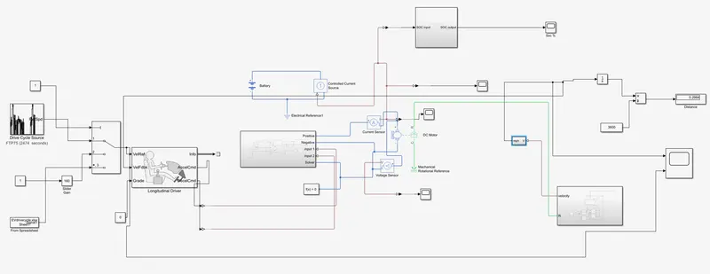
Blocks used in the model :
- vehicle body
- tire (magic formula)
- H bridge converter
- DC motor
- Controlled PWM voltage
- Longitudinal Driver
- Battery
- Controlled current source
- Voltage sensor
- Current sensor
- Multiport Switch
- Drive cycle
- Slider gain
- From spreadsheet
Block explanation:
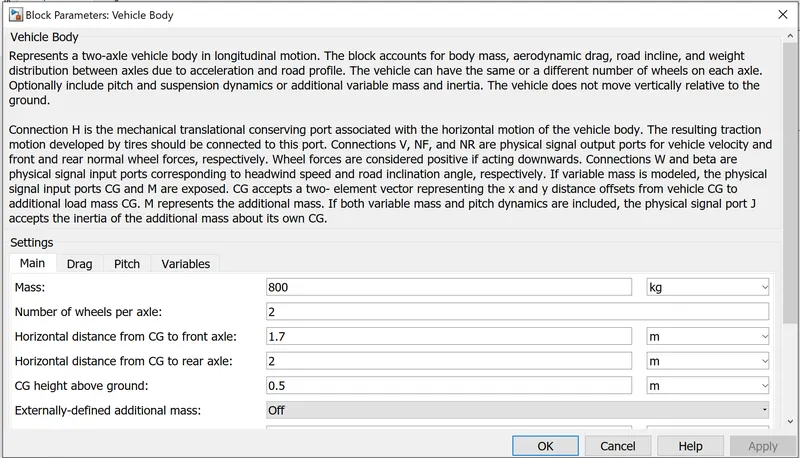
vehicle body :
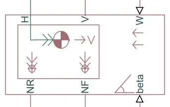
The vehicle body block repersents a two axle vehicle body in longitudinal motion.the vehicle can have same or a diff no. of wheels on each axle.vehicle have centre of gravity that is at or below the plane of travel.the block account for body mass,aerodynamic drag,road incline and weight distributer between axles due to accelaration and road profile.optionally include pitch and suspension dynamics.the vehicle doesnot move vertically relative to the ground.the mass,inertia,and center of gravity of the vehicle body can vary over the course of simulation in response to system changes.
input ports :
W - headwind speed (m/s)
beta - road incline angle (rad)
CG - center of gravity (m)
M - mass (kg)
J - external moment of inertia(kg*m^2)
Output ports :
V - Longitudinal velocity (m/s)
NF - Front axle normal force(N)
NR - Rear axle normal force(N)
Conserving Port :
H - Horizontal motion
H Bridge :
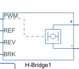
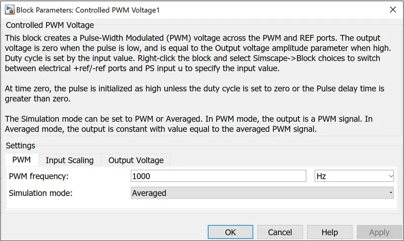
H bridge block represents an H bridge motor driver.the block has the following mode options :
PWM - the H bridge block output is a controlled voltage that depends on the input signal at the PWM port. if the input signal has a value greater then the enable thresold voltage parameter value, the H bridge block output is on and the value is equal to the output voltage amplitude parameter. if it has a less value then the enable thresold voltage parameter value,the block maintains the load circuit using :
- via one semiconductor switch and one free wheeling diode.
- via two freewheeling diode.
- via two semiconductor switches and one freewheeling diode.
The signal at the REV port determines the polarity of the output. If the value of the signal at the REV port is less than the value of the Reverse threshold voltage parameter, the output has positive polarity, otherwise, it has negative polarity.
Averaged - This mode has two Load current characteristics options:
- Smoothed
- Unsmoothed or discontinuous
Ports:
H : Thermal
- : Negative load connection port
+ : Positive load connection port
V- : Negative voltage connection
V+ : Positive voltage connection
PWM : pulse width modulated signal
ref : Reference
REV : Reverse
BRK : Brake
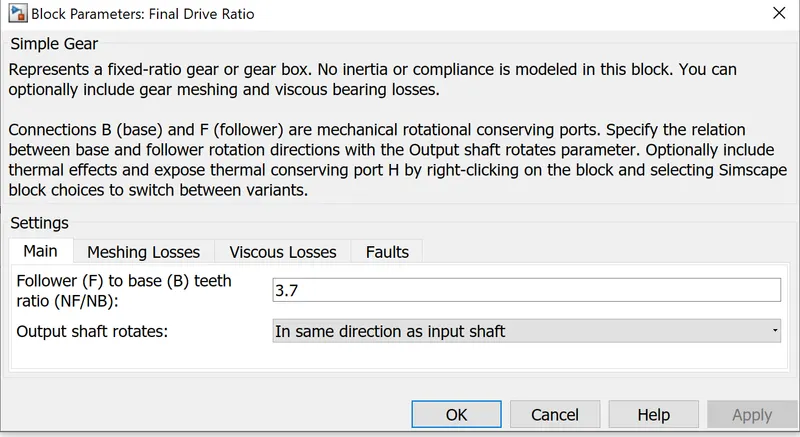
simple gear :
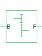
This simple gear block is fixed-ratio gear or gear box.Connections B (base) and F (follower) are mechanical rotational conserving ports. Specify the relation between base and follower rotation directions with the Output shaft rotates parameter. we can change the direction of shaft in both direction by click on the setting.
Ports :
B - connected with motor
F - connected with the wheel
Tire :
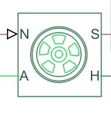
The tire(magic formula) block models a tire with longitudinal behaviour given by the magic formula,an empirical equation based on four fitting coefficients.the block can model tire under constant or variable pavement conditions.to increase the fidelity of the tire model you can specify properties such as tire compliance,inertia,and rolling resisrance.
ports :
N - normal force on the wheel
S - slip angle between tire and road
H - Wheel hub
A - Axle on which tires sits on
DRIVE CYCLE :
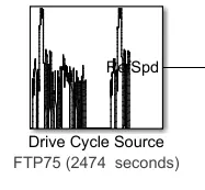
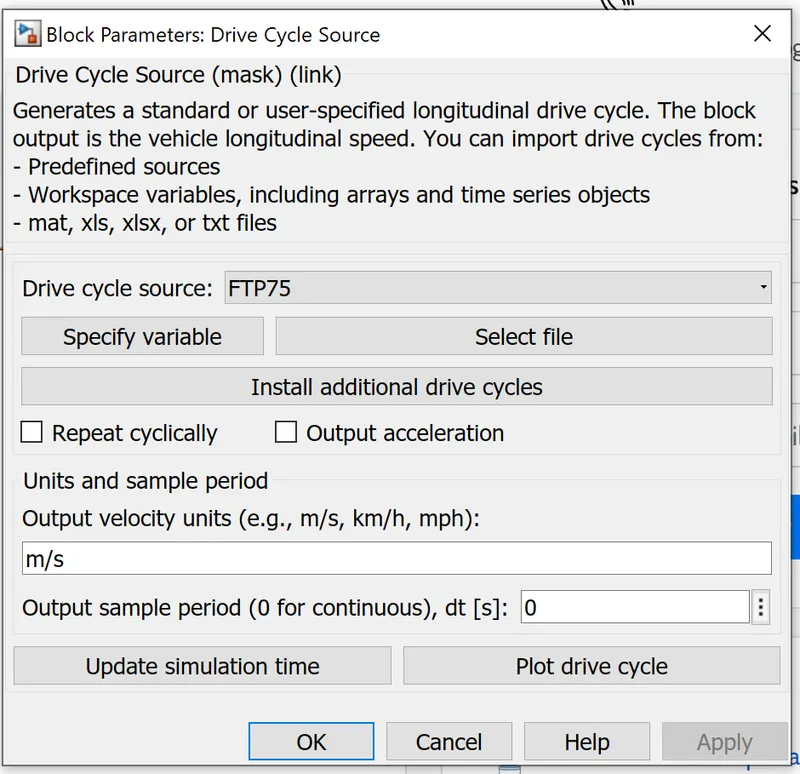
This drive cycle block is standard or user specified drive cycle.we can give any types of drive cycle to the input by adding the drive cycle to this block and then find the output of the drivecycle how it will behave and compare them with diff cycle or real time cycle aswell.we can customise the cycle and give the data in any form like by using excel,txt and matlab life aswell.we can plot drive cycle in this block aswell and we can choose miles/hr,km/h or m/s aswell.
Multiport switch :
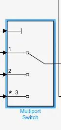
Multiport switch Pass through the input signals corresponding to the truncated value of the first input. The inputs are numbered top to bottom (or left to right). The first input port is the control port. The other input ports are data ports.we need to give constant block so we can give input from there and we can decide which drivecycle or ehich block we given as input and according to this it will give us output and tranfer to the appropriate block.we can give as many input port as we want.
Battery :
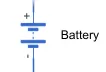
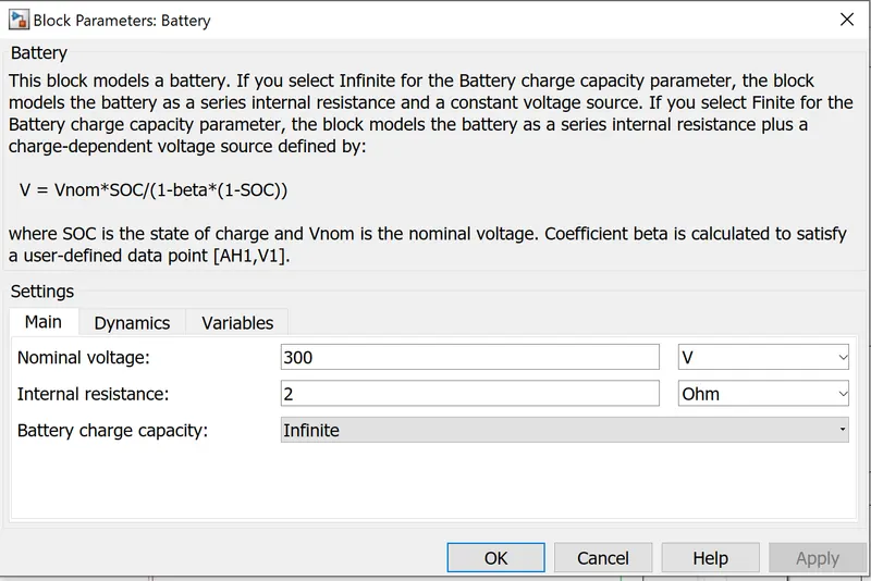
in simulink library many types of battery availabel this is simple one we use beacuse it will save our simulink times and we can do many things which this battery aswell for our model.here we have two option for battery charge capacity : infinite and finite.we can change nominal voltage, resistance and variables such as charge discharge,current voltage
Ports :
+ : positive terminal
- : negative terminal
controlled current source :
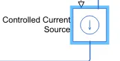
This controlled current source block represent an ideal current source that is powerfull enogh to maintain the specified current through it regardless of the voltag3e across the sources. the positive direction of the current flow is indicated by the arrow.
controlled PWM voltage :
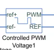
the controlled PWM voltage block represents a pulse width modulated voltage source. the block has two modeling varients,accessibible by right clicking the block in your block dia and then selecting the appropriate option from the context menu,
electric input ports - the block calculate the duty cycle based on the referance voltage across its ref+ and ref- ports.
PS input - specify the duty cycle value directly by using an input physical signal port.
Ports :
ref+ : positive terminal
ref- : negative terminal
REF - Floating zero volt referance
PWM : pulse width modulation signal
DC motor :
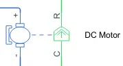
DC motor block represents the electric and torque characteristics of a DC motor using the following equivalent circuit model :
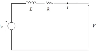
the resistor R corresponds to the resistance we specify in the armature resistance parameter.the inductor L corresponds to the inductance you specify in the armature inductance parameter.DC motor block is used to supply propulsion power to the whell through the gesr box.there are various types of DC motor block such as PMDC,BLDC.based on the requirment proper motor is used.
Electrical Ports :
- : Negative terminal
+ : positive terminal
Mechanical ports :
R- motor rotor
C - motor case
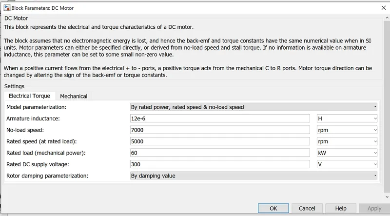
as DC motor block contains two parts one is electrical and another is mechanical. the electric part is connected to the controller port and machine is connected to the gear box and electrical referance. the parameter of the DC motor can be changed as per required condition.here we have chosen as rated power and no load speed.according to vehicle speed and gear ratio rated speed can be changed.
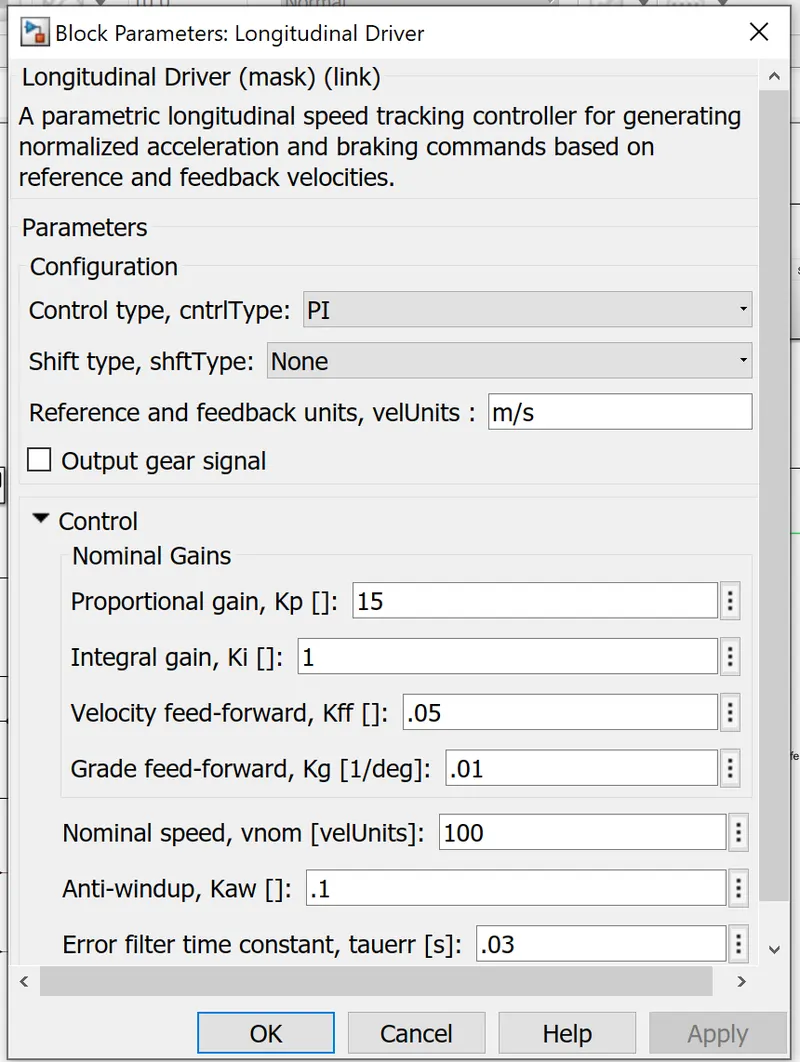
Longitudinal driver :
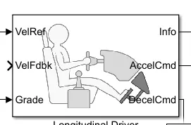
this block implements longitudental speed tracking controller. based on referance and feedback velocities, the block generates acceleration and braking commands that can vary from ) through 1. we can use this block to model the dynamic responce of a driver or to generate the commands necessary to track a longitudental drive cycle.
Input ports:
VelRef : Reference vehicle velocity
VelFdbk: Longitudinal vehicle velocity
Grade: Road grade angle
output ports:
Info: Bus signal
AccelCmd : Commanded vehicle acceleration
DecelCmd : Commanded vehicle deceleration
Vehicle model subsystems :
transmission system :
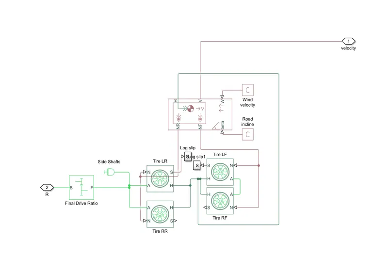
Explanation :
- transmission system is the important part of the vehicle it will transform the power to the wheels.
- here, for transmision the block i used is tire, vehicle body, simple gear,etc..
- this will help us to controll the tire, vehicle, gear ,throttle , power input ,etc
- there are 4 tire blocks used as 4 wheels of the vehicle and here we have connected the gearbox with the rear wheel to make it a rear wheel drive.
- in vehicle body block we have connected PS constant block to beta and wind velocity beacuse we asssume both are zero and tire slip is connecte with form and goto block.
Motor controller :
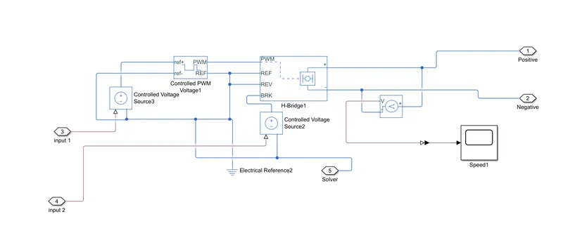
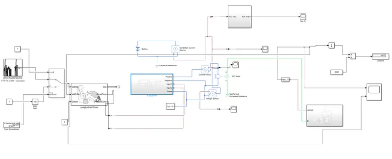
- This motor controller subsystem have H bridge,controller PWM voltage block and many small blocks.
- H bridge block is used to supply the power from the battery to the DC motor.
- H bridge has 4 switches that give DC voltage to DC motor and we can also control the supply of voltages.
- in this block we have PWM voltage,reverse and braking effect.
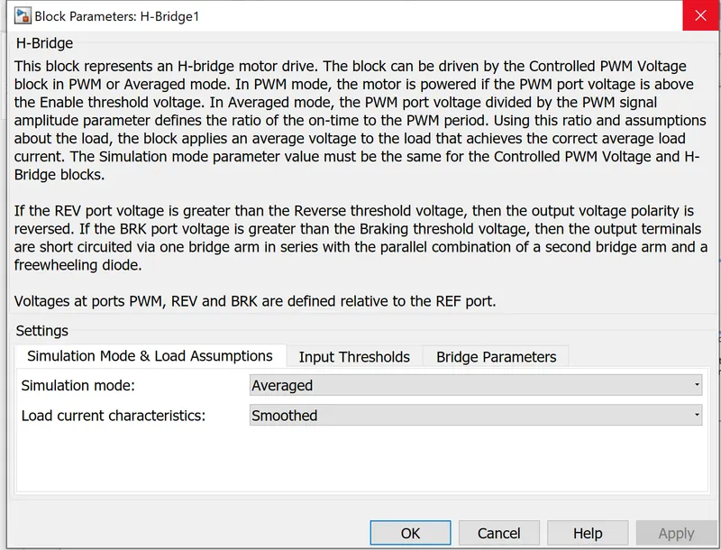
- here, we have two option for simulation mode,internal and external.as we choose internal we have a choice of PWM mode and avarage mode.
- here we chhose avarage mode beacuse it will faster then PWM mode.
- we kept regerative mode enable and load current characterstics smoothed.
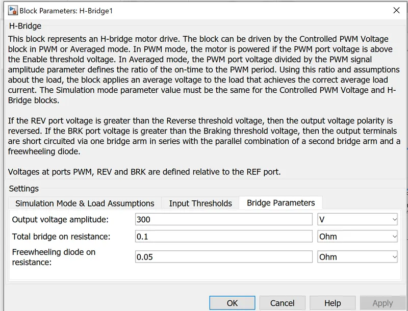
- also, we have to change the output voltage amplitude to the voltage we have supplied to the DC motor.
- This block will apply pulses and based on these pulses from the fixed battery voltage variable output voltage will be available to the motor and thr motor speed and motor torque are changed.
- this subsystem will control the power supply and transfer to the DC motor.
SOC calculation :
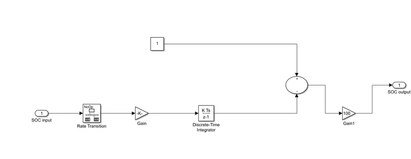
- the block used are rate transition, gain ,constant, add,etc..
- rate transition block takes input from controlled current source block as soc input signals and do a sampling of the signals and transfer to the gain block.
- gain block multiple the sampling signal with the rated voltage and give it to the discretetime intergrator block.
- Discrete time intergrator block integrates the signal and adds in to the constant given and supply it to gain block again.
- gain block multiplies it with 100 to give value in percentage and it will give it to the SOC output.
Distance calculation :
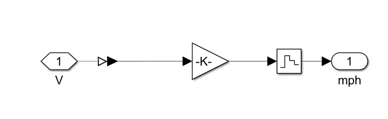
- the input is taken from the velocity feedback and then gain block multiplies it with 1.61 and give to the zero holder block so it will tranfer the value in mph.
so, here we take 3 input block such as drive cycle, slider gain and spreadsheet and we will use this one by one by using multiport switch block and diffrent diffrent running time and we will analyse the result.
1. FTP75 drive cycle as input :
Output :
SOC :
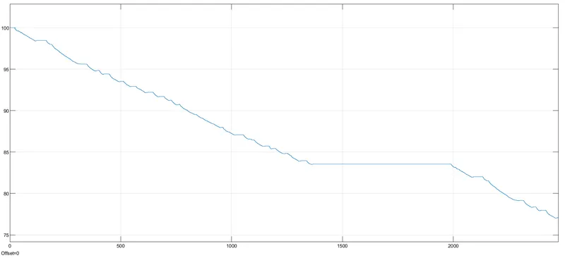
- Here we give the input as FTP75 drive cycle and run the model for 2474sec.
- here we can observe the SOC of the battery is been discharge by 13% from total 100% battery.
- SOC of the battery is 77% after the drive cycle completed.
- as we can observe that in graph curve is going sometimes littlebit up beacuse regenration happen and when vehicle in steadystate condition graph is linear.
- from 1300 to 1900 sec battery is in steadystate condition.
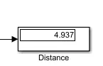
Distance travel in miles :
b. Velocity :
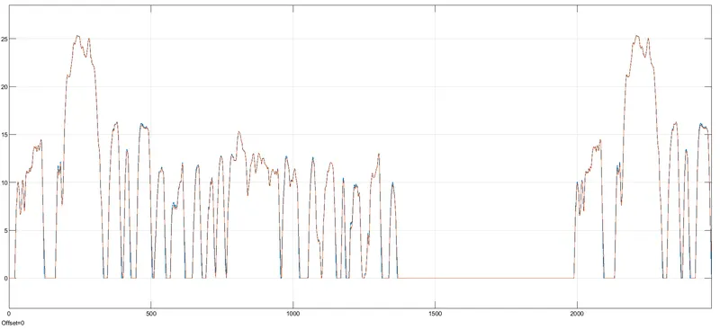
- Here we can observe that velocity by the vehicle is aproximately same as of standard drive cycle given as input.
- as per the standard drive cycle peak velocity attained by vehicle is 25mph which is same as standard drive cycle.
2. slidergain as input :
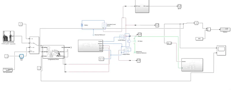
Output :
a. SOC :
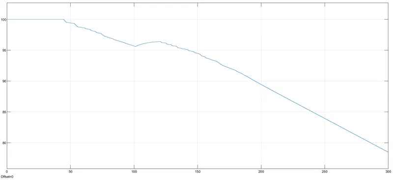
- Here we gave slider gain as input drive cycle and run the mode for 300 sec.
- here we can observe the SOC of the battery is been discharge by 12% from total 100% battery.
- SOC of the battery is 78% after the drive cycle completed.
- as we can observe that in graph curve is going sometimes littlebit up beacuse regenration happen.
- from 93% to 78% battery discharge is smoothly there is no any regenration happen. but it will good for the battery health.
Distance travel in miles :
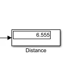
b. Velocity :
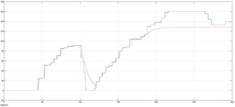
- As the input given to the vehicle velocity was the slider gain.
- we can observe that velocity by the vehicle is not exactly same as applied input.
- beacuse we change the throttle speed more faster so it will difficult for the vehicle to follow the driving cycle.
- at some points we applied sudden brake so vehicle take little more times to brake.
- and when i applied sudden accelaration vehicle can't abe to reach at that speed beacuse lack of power.
3. Spreadsheet as input :
Output :
a. SOC :
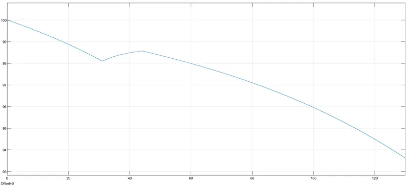
- Here we gave slider gain as input drive cycle and run the mode for 130 sec.
- here we can observe the SOC of the battery is been discharge by 7% from total 100% battery.
- SOC of the battery is 93% after the drive cycle completed.
- as we can observe that in graph curve is going sometimes littlebit up beacuse regenration happen this is due to little hard braking pressed so it will store more energy.
- from 30 to 45 sec battery is charging beacuse of regeneration through applied brake.
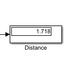
Distance travel in miles :
b. Velocity :
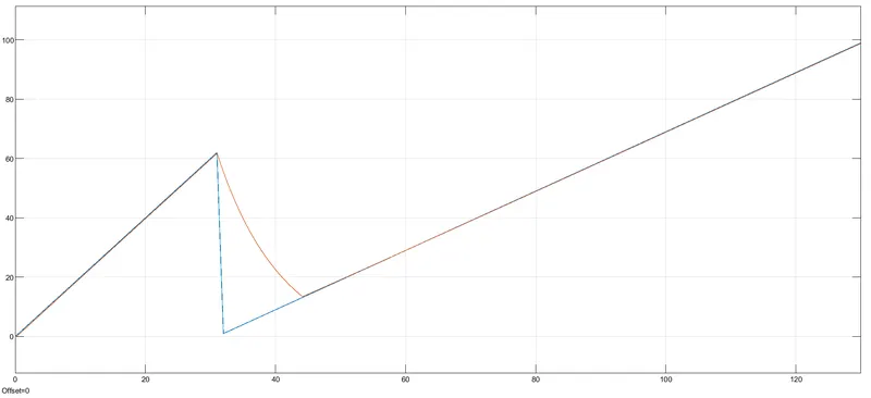
- As the input given to the vehicle velocity was the spreadshit.
- here we need to carefully save the spreadsheet and model in same path or folder.
- and we need to have spreadsheet data in workspace of matlab to access the file in simulink.
- we can observe that velocity by the vehicle is not exactly same as applied input when i applied sudden brake.
- beacuse we change the throttle speed more faster so it will difficult for the vehicle to follow the driving cycle.
- at 30 sec to 45 sec points we applied sudden brake but in real simulink time vehicle take more times to apply brake beacuse of the load of the vehicle and vehicle have to take care of the vehicle safety and passanger safety aswell.
Conclusion :
| Input | FTP75 drive cycle | slidergain | Spreadsheet |
| distance covered(miles) | 4.93 | 6.55 | 1.71 |
| Peak velocity | 25 | 130 | 98 |
| SOC (%) | 77 | 78 | 93 |