Final Project: Design of an Electric Vehicle
1. Create a MATLAB model of electric car which uses a battery and a DC motor. Choose suitable blocks from Powertrain block set. Prepare a report about your model including following:
Objectives:
1. System level configurations
2. Model parameters
3. Results
4. Conclusion
Sln.
The Electric car us that if fully or partially propelled by electric motors, using energy stored in recharagable batteries
* The First Practical electric card were produced in 1880 Electric car were popular late 19th century early 20th century
* Innovaiton and advanced development in the internal combustion and mass production of cheaper gasoline vehicles has led to a decline in the use of electric vehicles
* Diff types of electric car changed and are developed continously giving users and potential users choice todaythe world is increasingly familiar with the terms BEV, HEV PHEV and FCEV.
How does electric car work?
* When pedal of the card is pressed then controller takes and regulates electic energy from batteries and inverters
* With the controller set, the inverter then sends a certain amount of electrical energy to the motor
* Electric motor converts electrical energy into mechanical enegry. Rotation of the motor rotor rotates the transmission SO the wheels turn and then car moves
Types of electric cars:
1. Battery electric vehicle
2. Hybrid Electric vehicle
3. Pulg in Hybrid Electric Vehicle
4. Fuel cell electric vehicle
BLOCk Diagram of EV:-
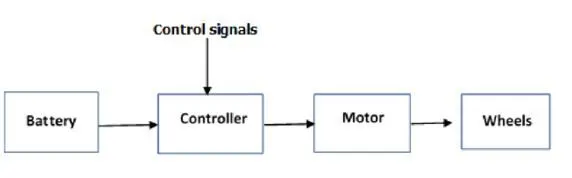
We have design our model with the help of tools availabe in MATLAB
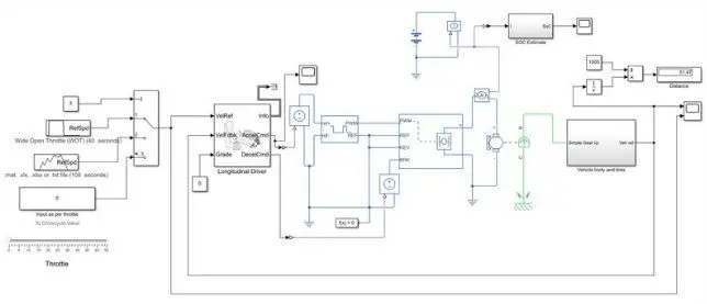
The Model not clear for looking so we have subsystem this model so we can clearley understand particular area of function.
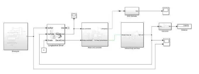
Explanation if model and the block used in the designing
DRIVE CYCLE:
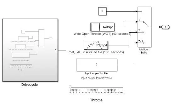
The Drive cycle Source block generates a standard of user-specified longitudinal drive cycle, The block output is the specified vehicle longitudinal Speed. We have 1 WOT test cycle. user defined and 1 real time input throttle which is nothing but a slider.
Here Multiport switch is used to select the drive cycles available which can done changing the value of constant block input tomultiport switch
LONGITUDINAL DRIVER:
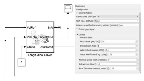
The Longitudinal Driver block implements a longitudinal speed tracking controller
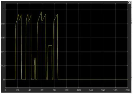
Based on refrence and feedback veloctities the block generates normalizied acceleration and braking commands that can vary from 0 through 1 We have use this block to model the dynamic response of a driver or to generate the commanda neccessary to track a longitudinal drive cycle. Its parameters settings is shown anove The block contains PI controller
MOTOR AND CONTROLLER:
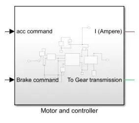
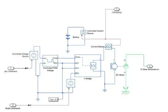
The acc command and decc command from longitudinal driver is given to H-Bridge through controller PWM voltage block. Outputs of which is given to DC motor. Explanation and configuration of individual block is shown below
Controlled PWM Voltage:
The controlled PWMm voltage block diagaram represents pulse width modulation Voltage source. Electrical input ports The block calculates the duty cycle based on the reference voltage across its ref and ref- ports This modelling varaiant is the default PS input Specify the duty cycle value directly by using an input physical signal port The settings of block is shown below.
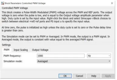
Dc Motor:
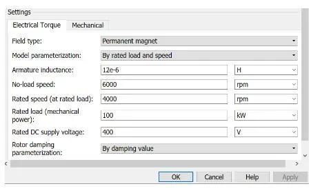
This block represents the electrical and torque characteristics of a DC motor
The block assumes that no electromagnetic energy is lost and hence the back emf and torque constants have the same numerical value when in SI units Motor parameters can eitther be specified directly, or derived from no load speed and stall torque, If no information is available on armature inductance this parameter can be set to some small no n zero value
When a positive current flows from electrical + to - ports a +ve torque acts from the mechanical C to R ports Motor torque direction can be changed by altering the sign of the back emf of torque constants The setting of block is shown below.
VEHICLE BODY AND TIRES:
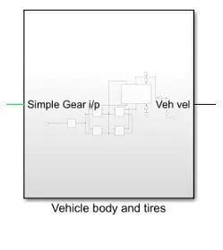
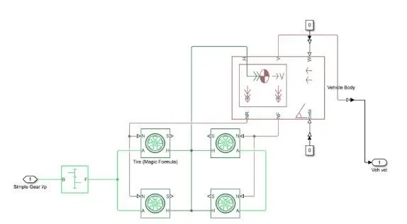
The o/p from the Dc motor is given to the simple gear which transfer the mechanical movement to tires Tiers are connected to the vechicle body. The vehicle uses a rear wheel drive system Block used is explain below.
Simple Gear:
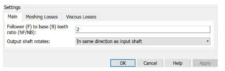
Reprsents a fixed ratio gear of gear box No inertia or compliance is modeled in this block you can optionally include gear meshing and viscous bearing losses
Conenction B base and F follower are mechanical rotational conserving ports. Specify the relation between base and follower rotation directions with the output shaft rotates parameter. Its setting is shown below.
Vehicle Body:
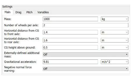
Reprsents a two axle velocity body in longitudinal motion. The block accounts for body mass aerodynamic drag, road incline and weight distribution between axles due to acceleration and road profile The vehicle can have the same or a different number of wheels on each axle. Optionally include pitch and suspension dynamics or additional varaiable mass and inertia, The vehicle does not move vertically relative to the ground.
Conenction H is the meachnical translational Conserving port associated with the horizontal motion of the vehicle body The resulting traction motion developed by tires should be connected to this port connection V, NF and NR are physical signal port for vehicle velocity and front and rear normal wheel forces respectively its setting is shown below.
SOC ESTIMATE:

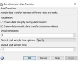
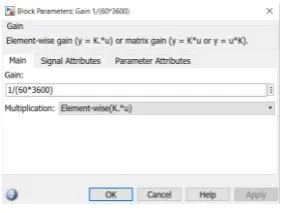
Current Sensor and controlled current source does the job measuring current from battery which is used to estimate SOC, Function and setting block used in shown below.
Rate Transition:
Gain:
Discrete tiime integrator:
Calculating Distance (m/s to km):
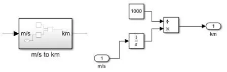
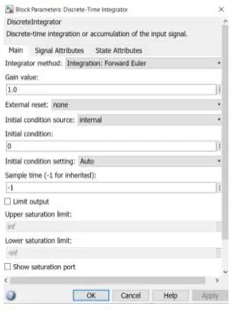
The integration velocity we all know is speed the integrator block does the same function here. To ge the distance in km we have divided the value by 1000
RESULTS:
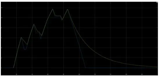
The drive cycle we have choosen here is to get knowledge about the vehicle behaviour and response according to the input.
Velocity:
The yellow line is the actual vehicle speed and the blue is our drive cycle input.
Acc Command:
Soc and Distance travelled:

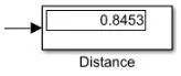
The SOC went down to 98% and regeneration can be seen which has given back energy to battery. The distance travelled was 0.85km (850m).
Conclusion: The Project was completed with a result..