Final Project
all the calculations can be accessed in the file
introduction: selection of springs and antiroll bars are done based on the vehicle level targets. this project involves the selection of the anti-roll bar for a lightweight sports vehicle that would provide the requisite auxiliary roll stiffness for a given stiffness value of the springs. the calculations need to be done while staying within the constraints specified under vehicle level targets. apart from doing the rolling analysis, tire stiffness analysis under static loading conditions for both the front and rear tire has to be done to assess how decreasing or increasing normal load affects parameters like corning stiffness, camber stiffness, and aligning stiffness. the third analysis involves preparing an understeer budget sheet that analyses the contribution of the kinematics and compliance characteristics of the suspension system to understeer or oversteer. this analysis can then be used to access which parameters need to be altered to give a net under-steer effect on the vehicle. since it is easier for a car to come out of an understeer situation, most passenger cars are designed to understeer for most of the handling, by stating, for the most part, an understeering car could become an over-steered one if it crosses its characteristic speed.
the characteristic speed of a car is given by: Uchar=sqrt(57.3*L*G/K)
L is the wheelbase
K is the understeer gradient
Deliverables:
- Rollbar outer diameters (front and rear) (inner diameter = 0) in mm
- Primary and secondary roll stiffness at the wheel center in ft-lb/deg
- Auxiliary roll stiffness (front and rear) percentage
- Tire stiffness plots (stiffness vs load)
- Understeer budget sheet
- Contribution bar chart
all the targets can be seen in excel sheet page 1
Stage 1
Roll Analysis: The first stage of the project involved the calculation of primary and auxiliary roll stiffness to meet the target roll gradient and also to calculate the appropriate size of Anti Roll Bar diameters. The vehicle parameters including the spring rates were specified as inputs.
a) Ride Rate: A 2 DOF Quarter Car Model is used to analyze the effects of the sprung, unsprung mass, and spring stiffness on vehicle vibrations. Using this model, a relationship between the ride rate and sprung mass which denotes the body hop natural frequency in Hz can be formulated. This formulation can further be extended to relate sprung mass natural frequency to static deflection under 1g loading condition. Ride Rate gives the combined effect of springs at the wheel center level and the tire rate. A term known as motion ratio is used to relate the change in displacement of the spring to the change in vertical wheel center movement. This wheel center movement is known as wheel rate(kW) which is expressed using the relation:
Kw=MR2*Ks in lb/in where MR is lesser or equal to 1
It is essentially the inverse of mechanical advantage and is used to relate spring rate to wheel center rate. Since wheels are the first point of contact between the road and the vehicle, the displacement of the wheel has a multiplying effect on spring displacement. The motion ratio must be kept fairly high so that the suspension system is effective enough to damp out road disturbances. Having a very low motion ratio would translate to a high spring displacement but an ineffective wheel center rate. This is the reason why the inclination of springs and the pivot points are key factors behind the motion ratio. Springs inclined at a very steep angle will reduce the effectiveness of the suspension despite having a fairly high motion ratio. Thus it is pivotal to keep a balance between the two.
Since the spring stiffness and their related motion ratio was specified, the wheel rate for both the front and rear tires was calculated using the above relation and after obtaining the effect of springs at the wheel center level, the quarter car model is used to calculate the combined effect of the wheel and tire rates.
ride rate(Krr) = (Kw*Kt)/(Kw+Kt) (lb/in)
Kw is wheel rate
Kt is tire rate
b)Primary and Secondary Roll Rate: The roll rate is nothing but the stiffness of the car during the roll. It is the torque resisting body roll per unit degree of body roll about the roll axis. Roll rates have a significant effect on cornering performance because it directly affects the distribution of tire lateral forces at each corner. The factors that affect roll rate include:
- Spring Rate
- Center of Gravity
- Track Width
- Weight Distribution
- Anti-Roll Bar Size and Stiffness
To calculate roll rate, we first begin with CG Height and weight distribution. Since these values have already been specified under vehicle level targets, we can calculate the roll moment which arises due to the difference between the roll center height and CG Height. Roll Center Height provides information about the proportion of the lateral load that is transferred through the springs and anti-roll bars (rolling moment) and the proportion of lateral load transferred due to suspension links(nonrolling moment). The line joining the front roll center to the rear roll center is the roll axis about which the body rolls.
-Roll Moment,harm(in)=hs-[Zf + ((Zr -Zf)*(wd)/L]
hs is the CG height (in)
Zf and Zr are the front and rear Roll center heights (in)
wd is Weight Distribution
-Rolling Moment/g of lateral acc, M`varphi`/Ay-harm*Ms/12
-Rolling Moment/g of lateral acc (gravity component) in lb-ft/g, M`varphi`/Ay=harm*Ms*`varphi`*0.017/12
-Total Rolling Moment/g of lat acc in lb-ft/, M`varphi`t/Ay=Lateral Component + Gravity Component
roll-gradient(`varphi`/Ay), which is the degrees of body roll/g of lateral acceleration has to be 3.8deg/g so accordingly the total roll rate required is
-K`varphi`=(M`varphi`t/Ay)RG in lb-ft/deg
since the total desired roll stiffness at the tire has been calculated, the next step would be to find the roll stiffness at the front-rear based on the lateral load transfer and also calculated primary and auxiliary roll stiffness.
-total lateral load transfer in(lb/g), Wl=Mt*h/T
Wl is lateral load transfer
Mt is the total mass of the vehicle
h is CG height
T is the track width
The total load transfer is the sum of lateral load transfer due to unsprung mass, load transfer due to forces on sprung mass, and load transfer due to roll. Since we are only interested in the roll component of lateral load transfer, we can subtract out the other two components. Also, to obtain understeer, the front lateral load transfer should be 5% higher than the rear load transfer. To get this, 5% of the total load transfer is added to the static front weight distribution of the car.
-Front Lateral Load Transfer (unsprung mass).LTus=Tyre Loaded Radius*Front Unsprung Mass/TW
-Front Lateral Load Transfer (sprung mass forces). Ws=Front Sprung Mass*Front RCH/TW
-Front Lateral Load Transfer (Roll Component), Wr=WI-(LTus+Ws) in lb/g
Next, the front total roll stiffness at the tire based on the load transfer component in ftlb/deg is calculated as, Ktotal_front- Wr*TW/(RG*12)
-The total rear roll stiffness would then be, Ktotal_rear=K`varphi`-Ktotal_front
The total roll stiffness that was obtained takes into account both the tire and wheel rates. The tire rate needs to be isolated since it is the spring and anti-roll bar which give provide roll stiffness to the vehicle.
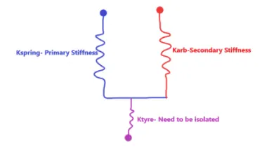
Since the spring and tire are connected in series, the tiring effect can be isolated by calculating the spring rate at wheel center level and tire rate, and then using the total roll stiffness, the tiring effect is removed.
-Roll stiffness from front wheel rate, K`varphi`sf=Kwf*TW^2/1375 in lb-ft/deg
-Roll Stiffness from rear-wheel rate, K`varphi`sr=Kwr*TW^2/1375 in lb-ft/deg
-Roll Stiffness from front tire rate. K`varphi`tf=Ktf* TW^2/1375 in lb-ft/deg
-Roll Stiffness from rear tire rate. K`varphi`tr=Ktr*TW^2/1375 in lb-ft/deg
TW is the track width of the car,
Kwf and Kwr are front and rear wheel rate,
Ktf and Ktr are the front and rear tire rates
To isolate the tire effect both at the front and rear, the formula used is
-Roll stiffness at the wheel center (tire effect removed)=Ktotal*K`varphi`t/(Ktotal-K`varphi`t)
The roll stiffness values obtained from the above formula give the 'Primary Stiffness'. To get the auxiliary stiffness, the value of wheel rate after tire effect isolation is subtracted from roll stiffness from the front/rear wheel rate.
The auxiliary stiffness values that were obtained for the front were slightly higher than the maximum constraint of 60%, but since the allowable deviation in target values can be 5%, so, this is acceptable.
c) Diameter of Anti-Roll Bar: The values of ARB stiffness were in lb-ft/deg which had to be converted to linear stiffness to find the diameter. The conversion factor from lb-in/deg to lb/in was:
-linear stiffness of ARB, Karb(lb/in)=roll stiffness of ARB*57.2958/(MR^2)*TW^2
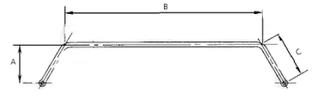
Since anti-roll bars are essentially beams of circular shafts. Thus, the shaft stiffness formula for a solid shaft(inner diameter=0) was used to obtain the diameter of ARB. The ARB properties have been assumed to be that of steel and so appropriate values of Elastic Modulus and Shear Modulus were chosen.
-Diameter of ARB=[{Karb *(0.4422A^2*B +0.2264C^3)}/500000]^0.25 (in)
-Diameter of ARB= (dia inches)*25.4 mm
Stage II- Tire Stiffness Analysis: The second stage of the project was to plot load vs stiffness and analyze how tire properties like cornering stiffness, camber stiffness, and aligning stiffness change with the applied normal load. The static load of the front and the rear tire was obtained through interpolation and then assessed as to how increasing or decreasing the normal load on the tire from static loaded condition affects the tire properties. A tool known as 'Format Trendline' was used in Excel to obtain a polynomial curve fit of different orders for these curves.
a) Normal Load vs Cornering Stiffness: At low slip angles, a linear relationship exists between normal load and cornering stiffness. The slope evaluated at zero slip angle gives the cornering stiffness of tire denoted by Ca. As the load increases the cornering stiffness which is a property of slip angle also increases and then it gradually goes through a translational zone. Beyond the translational zone, the frictional or sliding zone occurs where applying normal load would not produce any lateral force. The transition can be abrupt or gradual and this decides the breakaway characteristics of the tire. Property is known as 'Tyre Cornering Stiffness' shows that the cornering characteristic of the tire does not follow normal load.
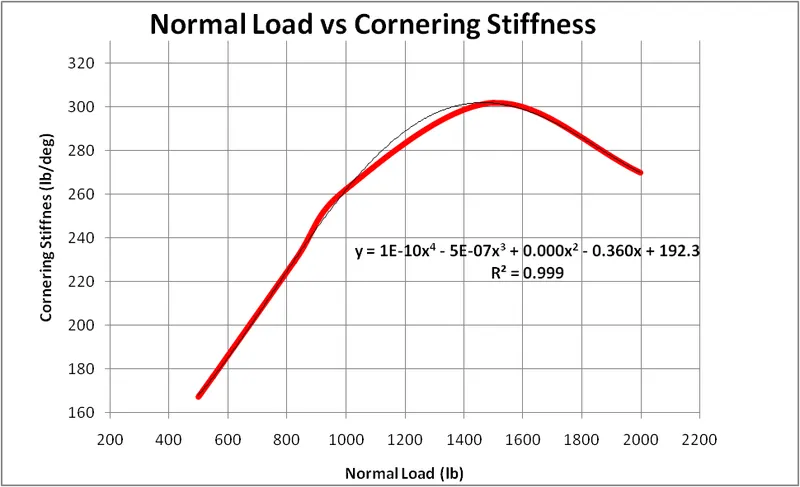
Linear Zone: Direct Proportionality with Normal Load
Translation Zone: Point from the end of normal load to peak cornering stiffness value
Frictional Zone: Point beyond the peak cornering stiffness value
Tyre Load Sensitivity is a measure of the tire's ability to produce lateral force for a given normal load. Tires are rubber compounds that are not infinitely rigid and they have a coefficient of friction between the road surface and itself. If the normal load is gradually increased, the tire will be able to produce a peak net lateral force up to a certain load. Beyond this load which is typically a limit handling condition, the friction cannot hold the tire and road surface any longer and as a result, increasing normal load would only start to saturate the tire which would result in a decrease in net lateral force. The tire saturates with loading and the graph above describes the load beyond which the tire saturates. Since the static load of the front and the rear tire is less than 850 lbs, the tire stays in the elastic zone.
b) Normal Load vs Camber Stiffness: A cambered rolling tire produces a lateral force in the direction of tilt. When this occurs at an 0 slip angle, it is called Camber Thrust. 'Camber Stiffness' is used to characterize the camber thrust capacity of the tire. It is expressed as the lateral force produced per unit camber angle and is about an order of magnitude smaller than cornering stiffness.
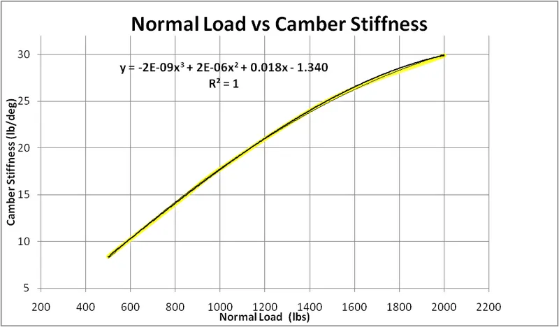
As the normal load on the tire is increased, the tire's camber stiffness gradually increases which suggests that the tire is cambering at a greater angle and producing an additional lateral force. This lateral force as a result of camber thrust gives rise to an aligning moment that aids the turn. This effect that is observed is very small in magnitude and is usually given due consideration in motorcycle dynamics.
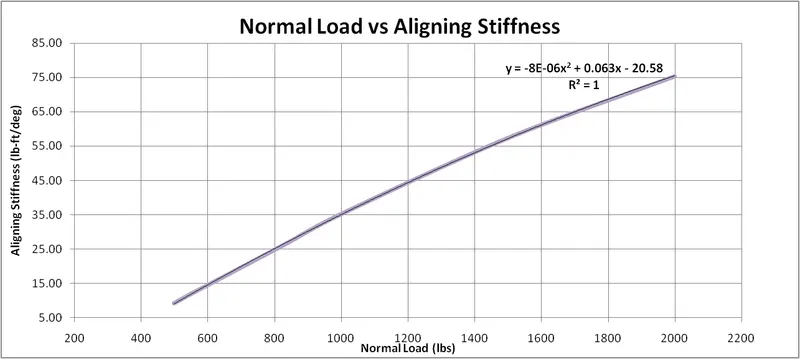
c) Normal Load vs Aligning Stiffness: When a tire print distorts, it continuously loads and unloads. During loading the energy is higher, whereas when the tire print unloads it follows a different curve suggesting a hysteresis loss. This energy loss is what gives rise to rolling resistance in tires where the loaded print has higher energy and thus produces higher force about the unloaded portion. During cornering, due to the same inertial force, the lateral force produced acts at a certain distance away from the contact patch. This lateral force gives rise to a moment that acts about the center of the contact patch and gives rise to 'aligning torque. Aligning Stiffness is the ability of the tire to produce a moment for a given slip angle.
Stage III- Under Steer Budget Sheet: Although tire cornering stiffness is used to develop the relation between steer angle and load/cornering stiffness ratio in steady-state handling conditions, it isn't the only contributor to the overall cornering force. Several other vehicle design parameters influence the development of cornering forces. The front and rear compliances are simply the sums of various kinematic and compliance parameters. The total 'Under-Steer Gradient' is simply the difference between the sum of front and rear cornering compliance.
The Under-Steer Budget Sheet is a great way to tabulate and study the effects of different K&C parameters of the suspension system on the overall under-steer. Depending on which parameter contributes to understeer, various hardpoint and bushing rate changes can be made accordingly. The chart below summarises the parameters that contribute to the overall under-steer budget:
i) Weight Distribution: It is the ratio of vertical load to cornering stiffness of the tire and is known as the coming compliance. Since cornering compliance varies with normal load, it is a dynamic property and a key contributor to the overall under-steer gradient. However, it is usually hard to control, and also no designer would heavily compromise on the overall weight distribution of the car just to slightly improve under-steer. Although it contributes about 50-60% to the overall budget, there is a limited scope of tuning this parameter.
ii) Rigid Body Aligning Torque: The lateral force acts at a point behind the contact patch of the tire to produce a moment about the tire center that tends to straighten out the tire during a turn. This moment is the aligning torque and it always is a source of under-steer. This effect along with the caster trail combine to produce the self-aligning torque.
-Aligning Torque Weight*(Pneumatic Trail/Wheel Base)* (Caf+Car/Caf*Car) in deg/g
iii) Roll Steer: The tie rod length error or the tie rod angle can lead to the suspension pulling on the tie rod that leads to the pulling of the car to one side during hard acceleration. If the tie rod does not intersect the axis of control arms it leads to toe out during jounce and rebound. On the other hand, if the tie rod is oriented in such a way that it does not meet the instant centerline, it would lead to toe out during jounce and toe-in during rebound. During cornering, the weight is transferred to the outer tire which leads to the toe out of the outer side increasing the radius of turn and thus giving rise to under-steer. At the rear toe-in at the outer tire would result in under-steer.
iv) Roll Camber: When the vehicle rolls, it gives rise to positive camber at the outer tire. This positive camber further gives rise to an effect known as camber thrust that results in the tire aiding the turn. At the front, 90% roll camber is typically chosen which means that for every 10" degree of roll, the tire would camber by +ve 1". At the rear, it is usually 50%.
-Roll Camber (deg/g): Roll Camber co-eff(deg of camber/deg of roll)*Roll Grad(deg of roll/g)*(Tyre camber stiffness (N of lat forces/deg camber)/Tyre cornering stiffness(N of lat force/deg slip))
v) Lateral Force Compliance Steer: The under-steer or over-steer effect produced due to this effect depends on the relative stiffness of the suspension and the steering. When the steering is more compliant than suspension, the application of lateral force acts to deflect the steering which leads to understeer. At the rear, this effect is produced due to the relative stiffness of the bushings and links.
-LFCS (deg/g): LFCS co-efficient (deg/kN)*Tire Lateral Force (kN/g)
vi) Lateral Force Compliance Camber: Since the lateral force acts at a point below all the suspension and steering linkages, the effect tends to pull the tire to a positive camber which gives rise to under-steer. Thus LFCC is always a source of under-steer.
-LFCC (deg/g)=LFCC co-efficient (deg/kN) *Tire Lateral force (kN/g) *Camber thrust/Cornering Stiffness
vii) Tire Aligning Torque: This is always an under-steer effect at the front and an oversteer effect at the rear. This is because the tire aligning torque always tries to straighten the wheels. Also, if the steering rack is flexibly mounted to the chassis, the understeer effect can be pretty large.
-AT Compliance Steer (deg/g)= ATCS co-efficient("/kNm)* Tire Aligning torque(kNm/g)
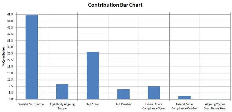
The contribution chart was plotted based on the contribution of the 7 parameters mentioned above to the overall under-steer gradient. Based on the above plot, the understeer of a vehicle can be analyzed and respective changes to the hardpoints and bushing rates can be made to increase or decrease the understeer gradient. The general conclusion drawn from the above plot are:
- As stated above, the weight distribution component is the largest contributor to the overall under-steer gradient (48.6%), and changing the weight distribution would adversely affect a lot of parameters which makes this property hard to control.
- The roll steer effect that arises due to the toe out of the outer front tire is the second dominant effect. So, if one needs to increase the understeer gradient, either the roll gradient or the roll steer co-efficient can be increased. Increasing the roll gradient would consequently also increase the contribution of roll camber as it is also dependent on it.
- The aligning torque and the lateral force compliance steer have almost the same contribution to the understeer gradient. Since aligning torque is a dynamic property that changes during cornering, it is much easier to change lateral force compliance steer co-efficient. So if one wants to induce under-steer, the steering can be made even more compliant than the suspension
- The contribution of aligning compliance steer to under-steer gradient is negligibly small (0.3%)