FINAL INDEPENDENT PROJECT
MECHANISM OF AIRCRAFT'S LANDING GEAR USING SOLIDWORKS
Aim:
- To build a model of Aircraft's landing gear assembly.
- To study its Mechanism and motion.
Introduction:
The main functions of landing gear, undercarriage to the primary structure of the aircraft, are to enable the aircraft for a taxi, safe landing and takeoff, and to support the aircraft in the rest of the ground operation. There are different types of landing gear used for various aircraft as per their requirements such as wheel, skids, skis, and floats or pontoons. Skids type landing gears are used in helicopters, Balloon gondolas, and tail dragger aircraft. Skis type landing gear used where aircraft used to takeoff or land in frozen lakes and snowy areas. If the operational surface of aircraft is water, the pontoon type landing gear is selected for those aircraft. Normally, the weight of the landing gear is about 3%–5% of the aircraft takeoff weight (Mohammad, 2012). Although landing gear is an essential component for safe landing and ground activities, it is a dead weight while aircraft is in the air. Thus, stowing the landing gear inside the aircraft reduces the unwanted aircraft drag, which in turn improves aircraft performance. Again, the landing gear can be classified on the basis of retraction nature mainly as (1) fixed type landing gear, that is, landing gear hangs underneath the aircraft during flight, and (2) retractable type landing gear, that is, landing gear stow inside the aircraft while in flight. All the modern commercial aircraft use wheel type retractable landing gear. In modern aircraft, there used to be two sections of landing gear, (1) main landing gear and (2) secondary landing gear. Main landing gear, positioned nearest to the CG of the aircraft, touches the ground first while landing and leaves the ground last during takeoff. Types of wheel arrangements are also different for various aircraft such as tail wheel type, tandem type, and tricycle type landing gear. Maximum single aisle passenger aircraft such as B737, A320, and A319, use tricycle type landing gear. In case more than two wheels are attached in one strut of main landing gear, the attachment is known as Bogey. The main landing gears of all large aircraft of modern age such as A380 and B747 are multibogey type landing gear. The weight of the aircraft can be distributed among a large number of wheels and also advantageous from the safety point of view with multibogey landing gear.
The major components of landing gear include in modern commercial aircraft are wheel assembly, air/oil shock-transferring components, braking system, extension/retraction and safety devices, gear alignment units, steering control elements, etc. Aircraft wheel assembly needs to support the entire load during taxi, takeoff, and landing. Wheels are made of aluminum alloy. Some magnesium alloy made wheels are also used. Tires are mounted on the wheel. Tires are made stiffer to absorb high impact load while landing and enable the aircraft to operate at high speed during taxing in after landing without blowing out or separating from rim. Aircraft tires are often tubeless or tube type. Aircraft tire tubes are constructed with the natural rubber compound. Nylon reinforcing fabric layered with rubber made heavy-duty tubes in order to impart strength.
In most modern aircraft, brake units are provided in main wheels whereas nose wheel or tail wheel without the brake. In early aircraft, brakes are not used instead rely on ground friction, tail skids, etc. Older large aircraft generally equipped with expander tube brakes, now in modern passenger aircraft, the trend is to use carbon disk brakes. For other landing gear components, high strength steel is used for its robustness properties. The constant effort to develop new economic, lightweight, durable, robust materials for landing gear made it possible to replace some of its steel components by using titanium alloys, even composite materials also introduced in some landing gear components. Recently, ultra strength corrosion resistance steels have been used in B787 and Airbus A400m. The single largest titanium application is found in main landing gear truck beam of Boeing B777. Applications of high-strength titanium alloys are also observed in titanium sliders of B787 main landing gear and gear links of Airbus A340. Aluminum alloys are also used in landing gear construction of modern passenger aircraft. Composite materials are used for the construction of main and nose landing gear door of Airbus A310-300, A320, A319, A321, A330, and A340. Similarly, the main and nose landing gear door of Boeing B767 and B777 are also made from composite materials. Carbon fiber braces are used for the B787 main landing gear.
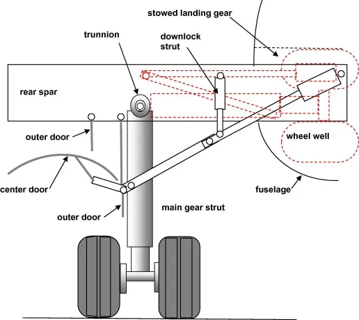
Landing gear retraction
The landing gear struts transmit their load to the airframe through the trunnion mounted on the rear spar of the wing and pivot about the trunnion for stowage within the wing and fuselage, as shown in Figure 7.35. Landing retraction mechanisms are often quite different in configuration, as can be seen in Figures 7.16 and 7.21–7.24, but are usually based on the four-bar linkage of kinematics. The schematic diagram in Figure 7.35 is presented to provide a general idea of the landing gear arrangement in the down and stowed positions.
Clearance must be allowanced between the tires and nearby components or housings. The maximum overall tire dimensions given in the manufacturer’s tire data tables must include a growth allowance due to use. In the case of a rotating tire allowance must be made for the diameter increase due to centrifugal force. Clearances between the tire and adjacent parts of the aircraft are determined by first computing the new tire envelope due to service according to the manufacturer’s specifications. The new envelope is denoted by the dashed line called the used inflated tire in Figure 7.36. This expanded outer envelope of the tire is usually called the “grown” tire. The lateral clearance denoted by Cw may be found from the equation
Cw=0.019Wg+0.23
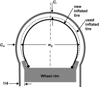
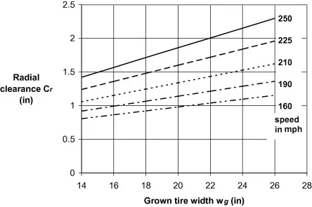
This side clearance is given in inches, as is the width of the grown tire, wg. The radial clearance depends upon the speed of the aircraft and the size of the tire and is shown in Figure 7.37 for rolling speeds up to 250 mph.
creating the models:
The landing gear in our assembly consists of mainly the following parts
- Disc Plate
- Telestropic strut
- Leg
- Linkage 1
- Linkage 2
- Wheel
- Whwwl Hub
- Shaft
- End cap
The final Assembly:
Annimation Link of the mechanism:
Conclusion:
Hence the landing gear assembly is built and the mechanism of its motion is studied