Internal Geneva Mechanism
Internal Geneva Mechanism
AIM:
- To Create 3D models for driver and driven wheels.
- To Perform motion analysis by rotating the driver wheel at 10rpm.
- To Obtain the following plots
- Contact force (between driving and the driven wheel) as a function of time.
- Angular Displacement of the driven wheel.
- To Compare the contact forces with and without "Precise contact"
- Show image for precise contact selection
- Export the results that you get to Excel and make the plots over there
THEORY:
1. Introduction
1.1 Multibody Dynamics
(MBD) system is one that consists of solid bodies, or links, that are connected to each other by joints that restrict their relative motion. The study of MBD is the analysis of how mechanical systems move under the influence of forces, also known as forwarding dynamics.
1.2 Geneva Mechanism
The Geneva drive or Maltese cross is a gear mechanism that translates a continuous rotation movement into intermittent rotary motion.
The rotating drive wheel is usually equipped with a pin that reaches into a slot located in the other wheel (driven wheel) that advances it by one step at a time. The main wheel also has an elevated circular blocking disc that "locks" the rotating driven wheel in position between steps.
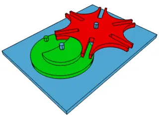
Fig. 1. Animation showing a six-position external Geneva drive in operation.
1.3 Contact Force
A contact force is any force that requires contact to occur.[1] Contact forces are ubiquitous and are responsible for most visible interactions between macroscopic collections of matter. Pushing a car up a hill or kicking a ball or pushing a desk across a room are some of the everyday examples where contact forces are at work.
1.4 Angular Displacement
Angular displacement of a body is the angle in radians (degrees, revolutions) through which a point revolves around a centre or line has been rotated in a specified sense about a specified axis. When a body rotates about its axis, the motion cannot simply be analyzed as a particle, as in circular motion it undergoes a changing velocity and acceleration at any time (t). When dealing with the rotation of a body, it becomes simpler to consider the body itself rigid. A body is generally considered rigid when the separations between all the particles remain constant throughout the body's motion, so for example parts of its mass are not flying off. In a realistic sense, all things can be deformable, however, this impact is minimal and negligible. Thus the rotation of a rigid body over a fixed axis is referred to as rotational motion.
The Present study is to analyze the motion study of an internal geneva mechanism and plot various graphs and compare the plots and explain the results.
2. Modeling and Assembly:
The emodeling of both the wheels as well as tshe assembly is being carried using SolidWorks.
i. Geometry of Driver wheel
ii. Driven Wheel
iii. The parts are assembled based on the dimensions determined using the drawings
3. Procedure
- 3D model is developed based on given drawings
- The parts are assembled based on the dimensions determined using the drawings.
- The motion of the wheels is to be constrained to rotation about their axes.
- A motor is to be defined at the axis of driving wheel at required rpm.
- Contact has to be established between the wheels and the simulation is ready to be run.
- After running the simulation required plots are to be extracted.
- Precision contact available in the settings can be used to determine the contact forces more accurately.
The final assembly setup:
Precise Contact For 10 Rpm
4.Output
i. Driver Wheel Output
- Angular Displacement Driver wheel
- Angular velocity at 10 rpm
- Angular velocity at 20 rpm
- Animation Video of Internal Geneva Mechanism At 10 rpm
ii. Driven Wheel Output
- Angular Displacement Driven wheel
iii. Contact Force
- Contact force at 10rpm
- Contact force at 20rpm
- Contact force 10rpm v/s 20rpm
5. Results
- The angular displacement plots show a linear trend for the driving wheel, the driven wheel describes curves during motion along with intervals of time at rest.
- The number of peaks increased linearly with RPM as expected.
- Precision enabled study shows higher contact forces as compared to one without.
- For10 rpm, the angular velocity of the driver wheel is almost steady state with time.