FINAL INDEPENDENT PROJECT
DUCTED PROPELLER FLOW ANNALYSIS USING SOLIDWORKS
Aim:
- To run the flow simulation of the Ducted Propeller.
- To compare the efficiency of the propeller with Ducting to that of the normal efficiency of propeller.
Introduction:
The Principles
Let’s begin to understand how ducting works firstly by explaining what a propeller is. As some of you know, a propeller is a small wing fitted at an angle in a radial configuration around a central hub shown in the cross-sectional image below [1]. If you’ve read my ‘How Do Aircraft Fly?’ article you’ll have an understanding about how wings create lift, but for those of you who haven’t, I’ll briefly cover this now.
According to Newton’s third law, “every action has an opposite and equal reaction” which can be seen everywhere in our universe. It applies to wings and flight because as a wing travels through the air it splits it into two [2]. The wind, as it is being bent, is hitting into the wing and being pushed downwards. As a consequence, an equal and opposite force of the wind being pushed down by the wing is that the wind pushes the wing upwards [2] (shown by red arrows); creating lift.
On the other side of the wing a different process is happening. For this, Bernoulli’s principle must be explained. As a whole, one of his theory states that, as a fluid’s speed increases (including air); it’s pressure decreases. This can be linked to the airflow over the wing because on top, the airflow is travelling faster due to the fact it has further to go around the curved surface; creating an area of relatively low pressure shown below [3]. Due to this, two things are happening. 1, the wing is being sucked into the area of low pressure and 2, the greater difference between the high and low pressures above and below the wing increases the lift generated.
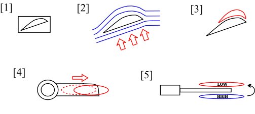
All very well, however we wouldn’t need to duct propellers if it wasn’t for this next phenomenon. Imagine a ball on the end of a string hanging vertically. Now swing it around fast; what happens? The ball and the string lie horizontal when spun fast enough. This is because the ball is experiencing centrifugal force, the force that throws things outwards to the edge of their limiting circumference, for example, the length of the string tied to the ball. This force is important because it causes the area of low pressure on top of the wing to be flung outwards shown in the illustration above [4]. Again I must shamelessly plug another of my articles ‘How Do Winglets Work?’ because I’m only briefly going to talk about the next section and if you would like to know more please go read that article.
Due to a process called diffusion, an area of higher pressure or concentration will want to move towards an area of lower pressure or concentration to balance the volumes, and here on the wing we find two areas; one of high pressure and one of low pressure. As mentioned before the areas of pressure above and below the wing are flung outwards by centrifugal force until they meet with no wing in between them [5]. With no wing in the way, the high pressure if free to move towards the area of low pressure [5]. As a consequence a spiralling effect happens and vortices are made (see image below).
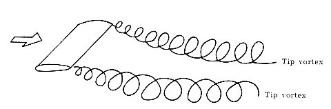
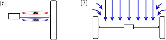
These spiralling vortices reduce efficiency because they convert useful energy being used for lift into the spiralling movement of air at the tips of the wings. How do we stop this? Simply, with a fence. Winglets on airplanes are the tiny fences; they get in the way and stop the areas of pressure from getting to each other and reduce the formation of vortices dramatically. In our case the duct is the fence (see below) [6]. The area of high pressure can no longer move around the outside of the wing because the duct is stopping it from doing so [6].
Nevertheless, this is not the only way ducts increase the efficiency of propellers. If you look at the design of a duct you’ll see it’s normally a wide entrance to allow as much airflow in as possible, but on the large scale it can be seen as a narrow pipe. Confused? Well Bernoulli’s principal shows that as the radius of a pipe decreases the liquid flowing through it speeds up and it’s pressure drops. The duct is like a small pipe. As air is forced into the duct it accelerates [7]. This means that a prop with a greater pitch to it can be fitted to keep up with the speed of the airflow and not require and more power from the motor, or a less powerful motor could be used to swing a larger propeller. In both instances gains are made from the improved efficiency.
The Practicality
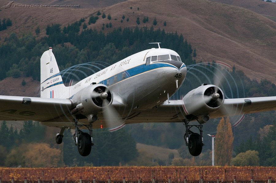
The discovery of ducting propellers in around the 1930s has led to the development of turbo fan engines used on many jetliners today. The large fans of these engines are ducted because the duct can be designed as the housing of the engine. Whereas on propellers of Cessna 172s for example, designing a duct around them would add extra weight, complexity and wouldn’t look as nice, negating the benefits of the efficiency.
Construction of model:
The model consists of 3 parts
- moter shell
- propeller blades
- duct
Steps to run the Simulation:
- create a defined geometry.
- start a new external flow study.
- create a basic mesh.
- Create the surface goal plots for the blades to study the velocity,pressure,and force.
- create cut plots for velocity.
- create the flow trajectries.
- add the equation goals
- run the simulation
Results:
velocity plot
Annimation of velocity variation:
Flow trajectries:
Annimation of flow trajectries:
Output of goal plots:
| Goal Name | Unit | Value | Averaged Value | Minimum Value | Maximum Value | Progress [%] | Use In Convergence | Delta | Criteria | |
| SG Average Static Pressure 1 | [Pa] | 100738.8858 | 100671.551 | 100286.9968 | 100875.7477 | 100 | Yes | 588.7508774 | 2088.221415 | |
| SG Average Velocity 2 | [m/s] | 117.3956853 | 117.3956853 | 117.3956853 | 117.3956853 | 100 | Yes | 2.84217E-14 | 1.17396E-06 | |
| Propeller Trust Force (X) 3 | [N] | 345.8281378 | 465.94735 | 345.4507889 | 618.8001816 | 100 | Yes | 125.4202181 | 339.2116986 | |
| Trust Force by Duct | [N] | 62.17498056 | 50.50466163 | -9.13160372 | 85.08173428 | 100 | Yes | 94.213338 | 98.41992077 | |
| Total Trust | [N] | 408.0031184 | 516.4520116 | 407.325975 | 672.3945781 | 100 | Yes | 41.79898782 | 364.4135839 | |
| Iterations [ ]: 52 | ||||||||||
| Analysis interval: 21 |
Theoritical caluculation of the trust force:
Calculation
An empirical formula to test whether a duct (kort nozzle) is effective is provided in Amtsberg's paper.
PD / (D^2.VA^3) > 1.6
where,
- PD - shaft output in KW
- D - propeller diameter in meters
- VA - inflow velocity of propeller without duct
In addition the following conditions also apply:
- No efficiency loss due to cavitation
- The propeller diameter is not restricted by the duct.
Because of the friction along the duct, the duct becomes only more efficient at higher loading. This is typical for ships at lower speeds, from tugs to tankers. It also reduces the rotational losses.
Conclusion:
- By reducing propeller blade tip losses, the ducted fan is more efficient in producing thrust than a conventional propeller of similar diameter, especially at low speed and high static thrust level (airships, hovercraft). ... Ducted fans offer enhanced safety on the ground.
- Advantages are increased efficiency at lower speeds (<10 knots), better course stability and less vulnerability to debris. Downsides are reduced efficiency at higher speeds (>10 knots), course stability when sailing astern, and increase of cavitation. Ducted propellers are also used to replace rudders.
- At high propeller loadings a duct can increase efficiency. The basic function of a duct is to increase efficiency. This is especially true in case of high thrust-loading coefficient. Tugs achieve on an average efficiency improvement of 20% and bollard pull increase of 30%.
- A duct accelerates the flow in the propeller plane and generates part of the total thrust.
- Increased course stability is achieved.