FINAL INDEPENDENT PROJECT
SURFACE MODELING OF BMW M6 CAR
OBJECTIVE-
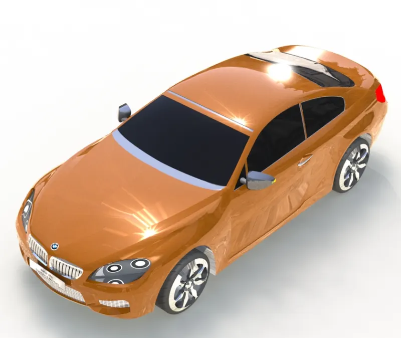
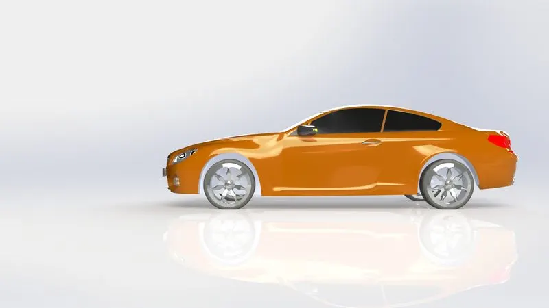
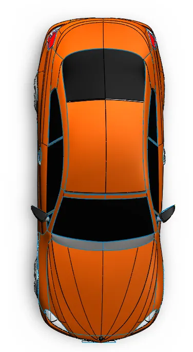
- Making a 3D model of a car by using 2D and 3D sketches or by using different surface options available on Solidworks and rendering it to a photo-realistic view in a 3D environment.
- To get knowledge on different surface options of Solidworks and also creating complex geometries and shapes of a car that might otherwise be impossible using standard extruded bosses, revolves, sweeps, and lofts.
INTRODUCTION-
- Surface modeling allows the creation of more free-form shapes. The creation of complex surfaces is easier in comparison with other modeling techniques. You can create extruded surfaces from models that include 2D or 3D faces and knit the extruded surfaces to surrounding features.
MODELLING PROCESS-
Target Model- BMW M6 sereis
Software Used- Solidworks 2017 Premium
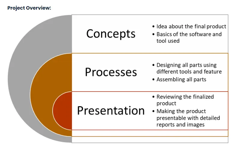
DESIGN STAGES-
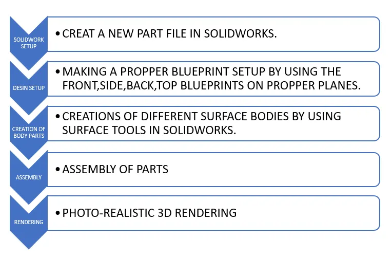
DESIGN FLOW CHART-
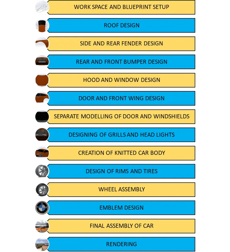
Features and tools:
Surface:
The following are the important surface modeling tools used:
Extrude, Sweep, Loft, Boundary Surface, Offset, Ruled Surface, Fill, Extend, Trim, Knit, Move/Copy

Solid
The following are the important solid modelling tools used:
Boss/Base: Extrude, Revolve, Sweep, Loft, Thicken
Cut: Extrude, With Surface
In addition to the above tools, there were a few tools common to both types of modelling that found extensive use in this project. They are:
Pattern/Mirror: Linear pattern, Circular pattern, Curve driven pattern, Mirror
Other features: Fillet/Round, Chamfer, Shell, Flex, Combine, Intersect, Split, Move/Copy, Delete/Keep body

Sketch Tools
The Sketch Picture tool was used to import the blueprints into the workspace. Most of the sketch tools used were basic like line, circle etc. The most important sketch tool used is the Spline. Also Offset and Convert entities tool were used to create sketches from existing sketches or edges.

Curve Tools
While the Projected Line tool was the mostly used tool in this category, the Split line tool was also used for projecting a sketch on to a face or a surface.
Reference geometry
One the most widely used feature in this project is the creation of reference planes with respect to existing planes or sketches. Since there were a considerable number of new planes, the naming of these planes was done based on the distance from the reference planes or sketches from which they were created. The creation of a reference axis was done for aligning the wheel in the final assembly.
Face
The Delete face tool was used on a few instances.
The important tools used for this project have been detailed in the explanation of various stages of the project.
Design Process
Units
The CGS unit system has been used for this project.
1. Set-up stage
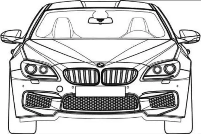
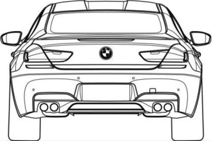
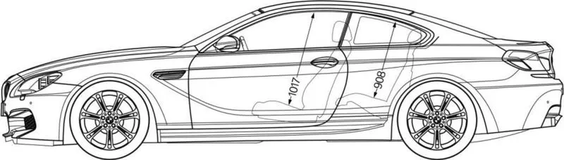
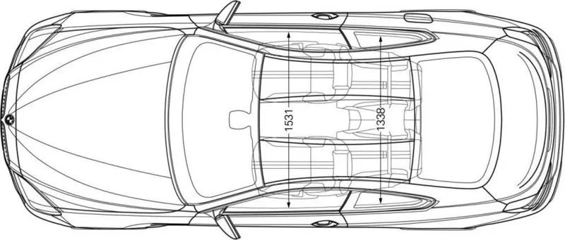
Workspace and Blueprint setup
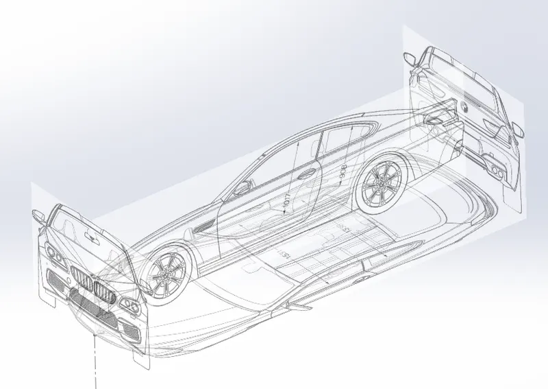
FRONT VIEW BLUEPRINT
BACK VIEW BLUEPRINT
MID VIEW BLUEPRINT
TOP VIEW BLUEPRINT
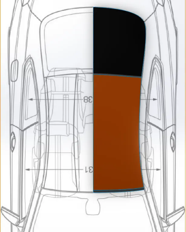
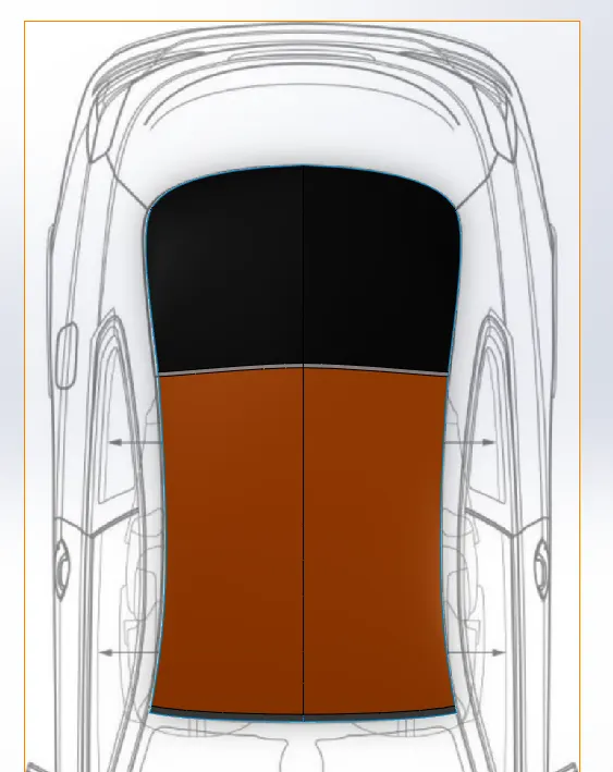
2. ROOF DESIGN
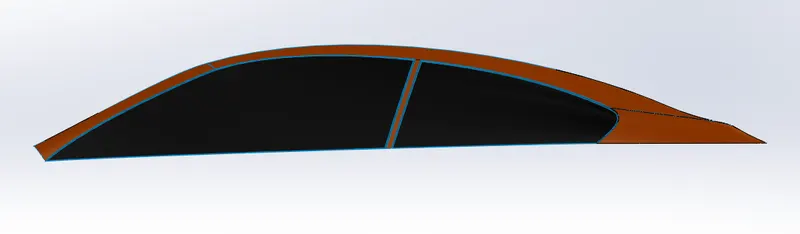
3. SIDE WINDOW AND FENDERS :-
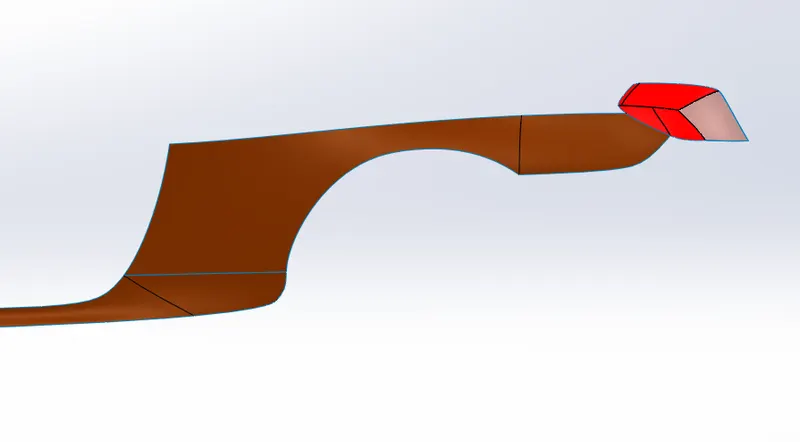
4. REAR FENDER:-
5. FRONT FENDER:-
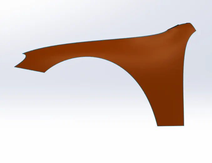
6. HOOD DESIGN:-
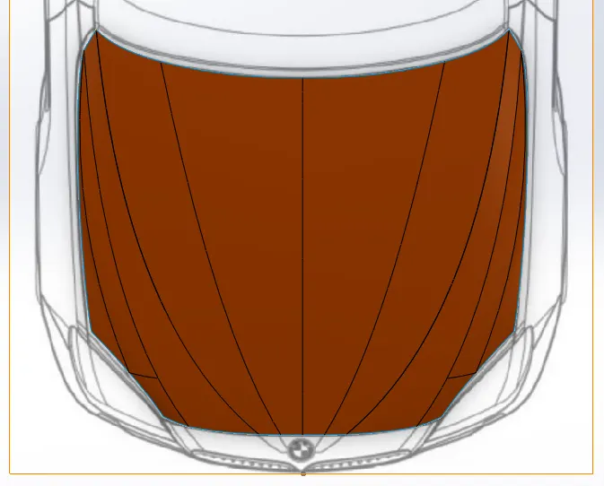
7. WINDSHIELD DESIGN:-
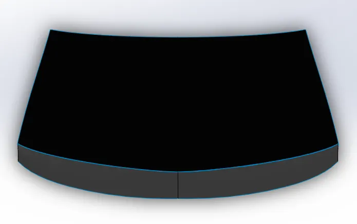
8. DOORS AND FRONT WING DESIGN:-
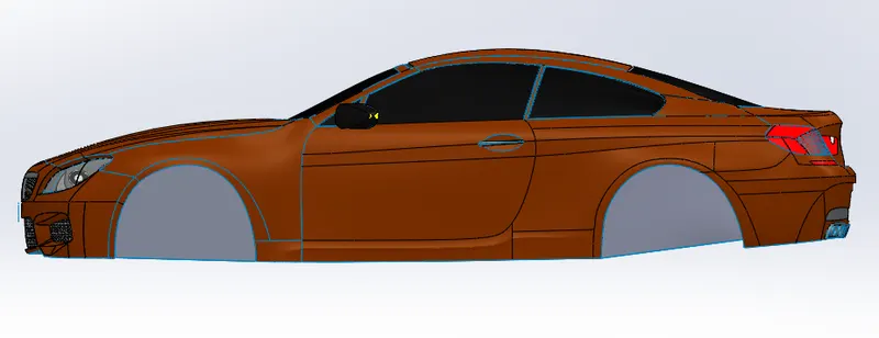
9. DOOR
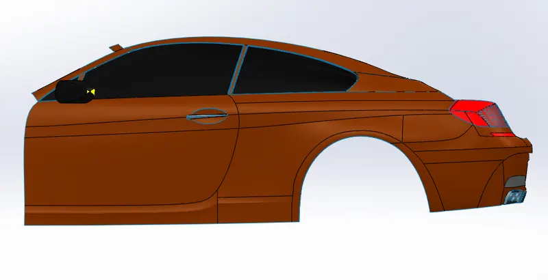
10. BACK DOOR:-
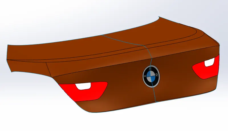
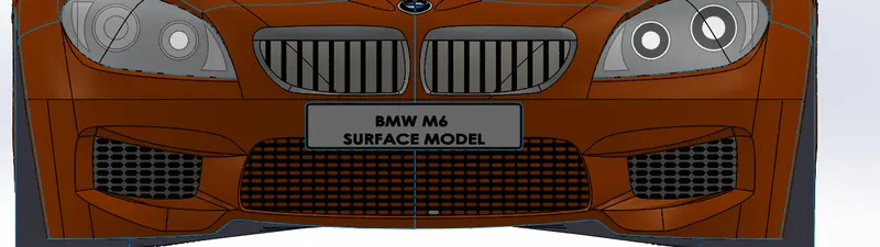
11. FRONT BUMPER
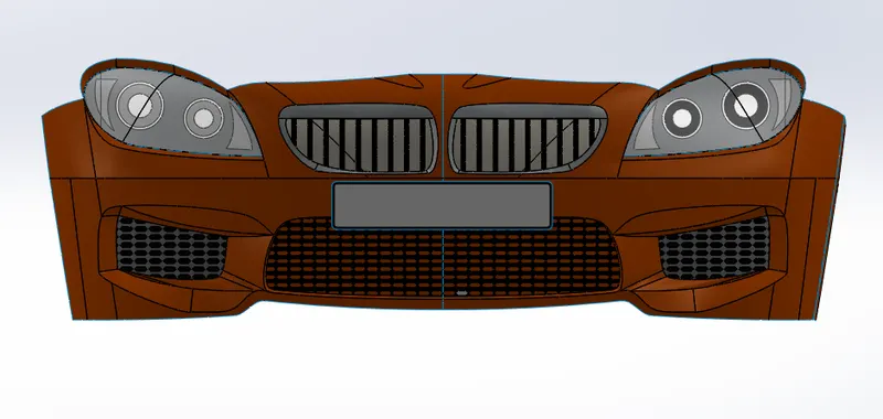
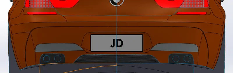
12. REAR BUMPER:-
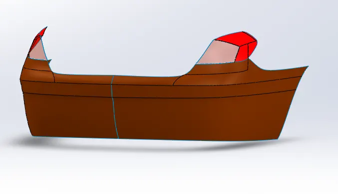
13. REAR GRILLS:-
14. FRONT GRILLS:-
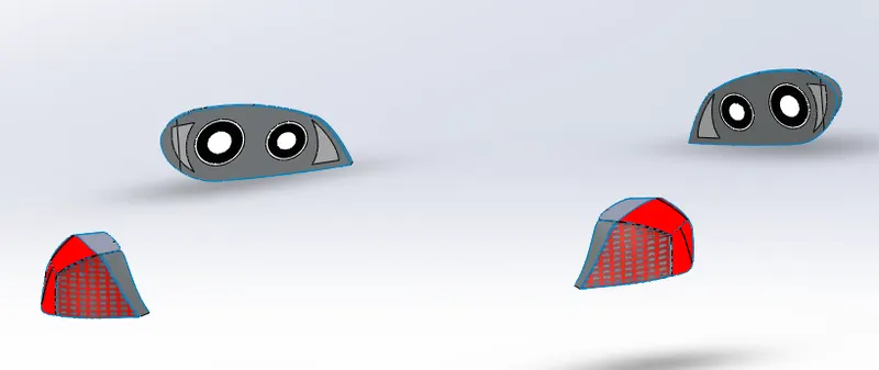
15. FRONT AND REAR LIGHTS:-
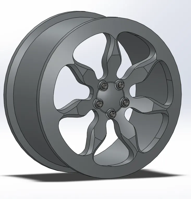
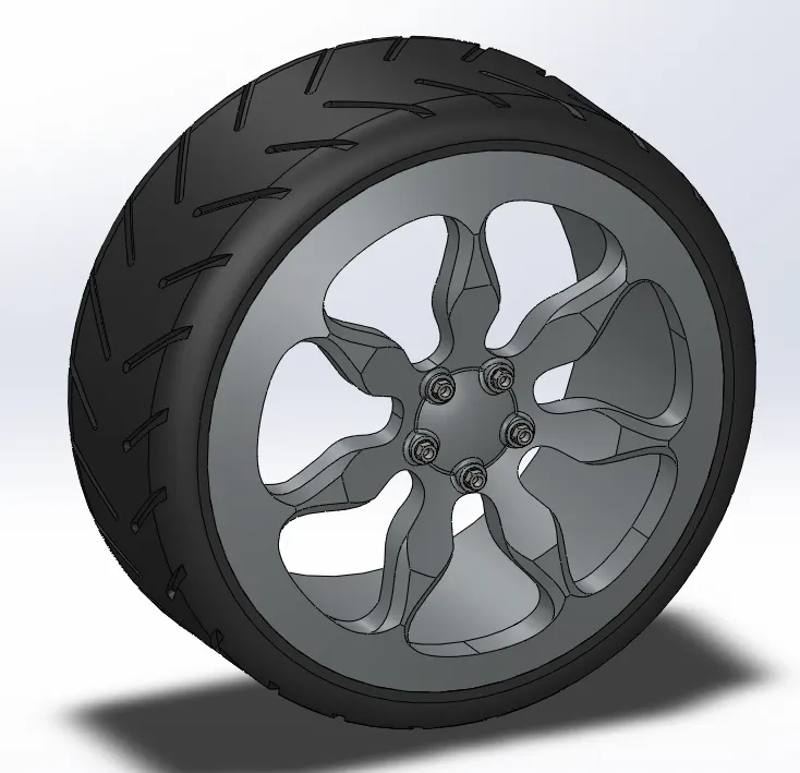
16. WHEEL DESIGN:-
RIM
TYRE-
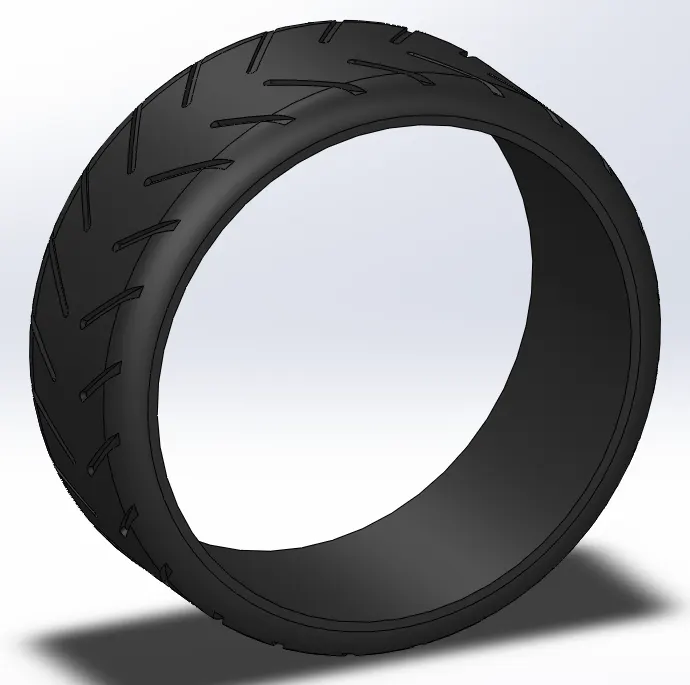
WHEEL ASSEMBLY-
17. EMBLEM DESIGN

18. KNITTED CAR BODY
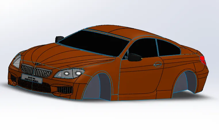
19. MODEL ASSEMBLY:-
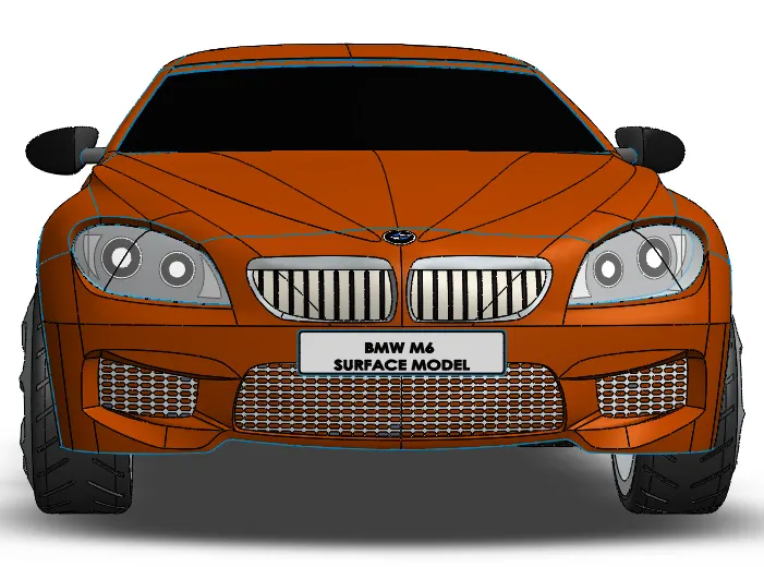
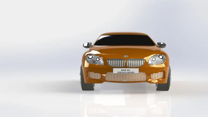
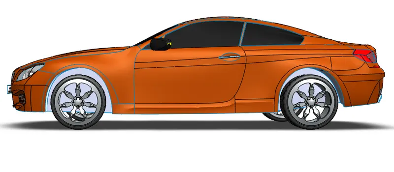
STANDARD VIEWS-
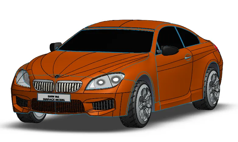
FRONT VIEW-
SIDE VIEW-
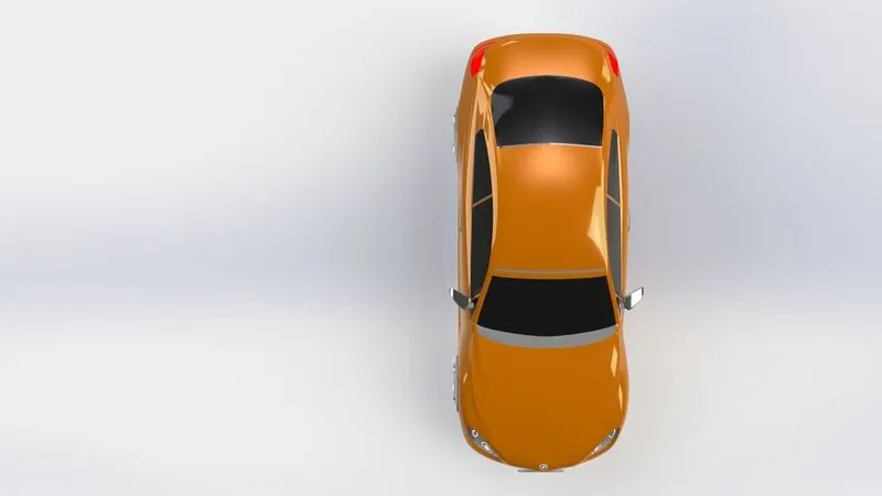
TOP VIEW-
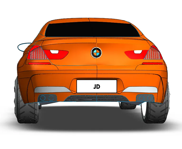
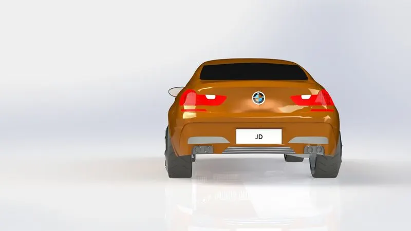
BACK VIEW-
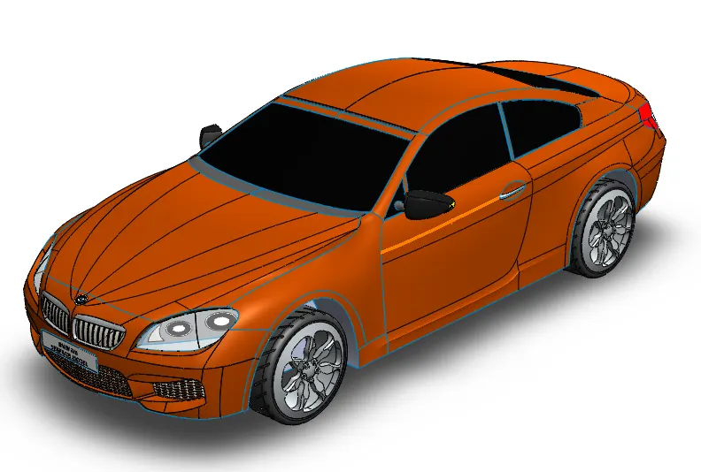
ISOMETRIC VIEW-
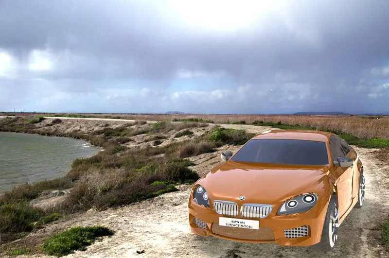
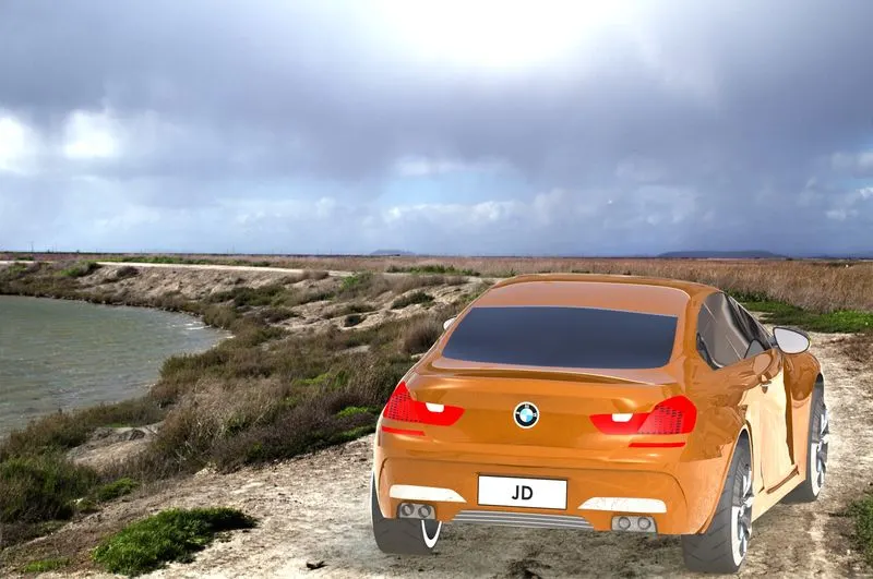
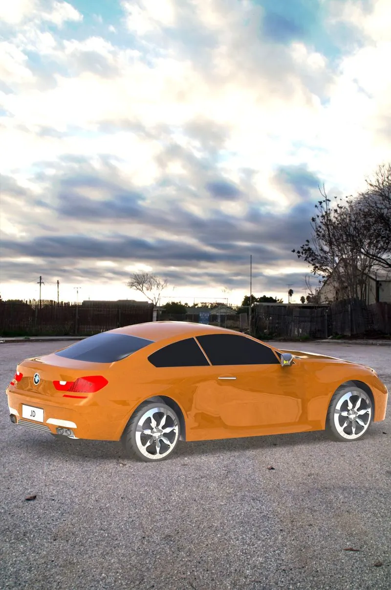
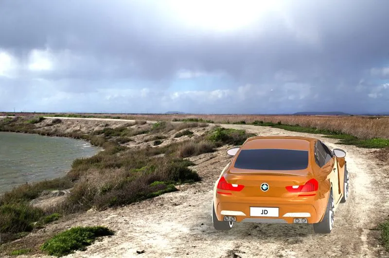
20. PHOTOREALISTIC RENDERING OF THE MODEL-
CONCLUSION
This project successfully achieved in imparting a great deal of knowledge regarding simple and complex surface modelling tools in Solidworks through successful completion of BMW M6 MODEL.