FINAL INDEPENDENT PROJECT
Design, Assembly and Rendering of a Tractor using SolidWorks and SolidWorks Visualize
Objective:
- Design the parts of the Tractor
- Assemble the parts in solidworks assembly.
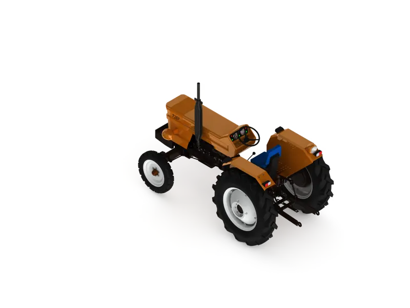
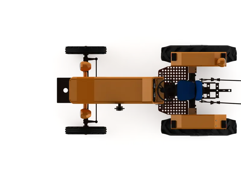
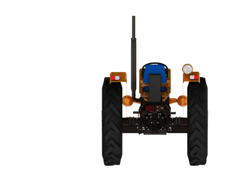
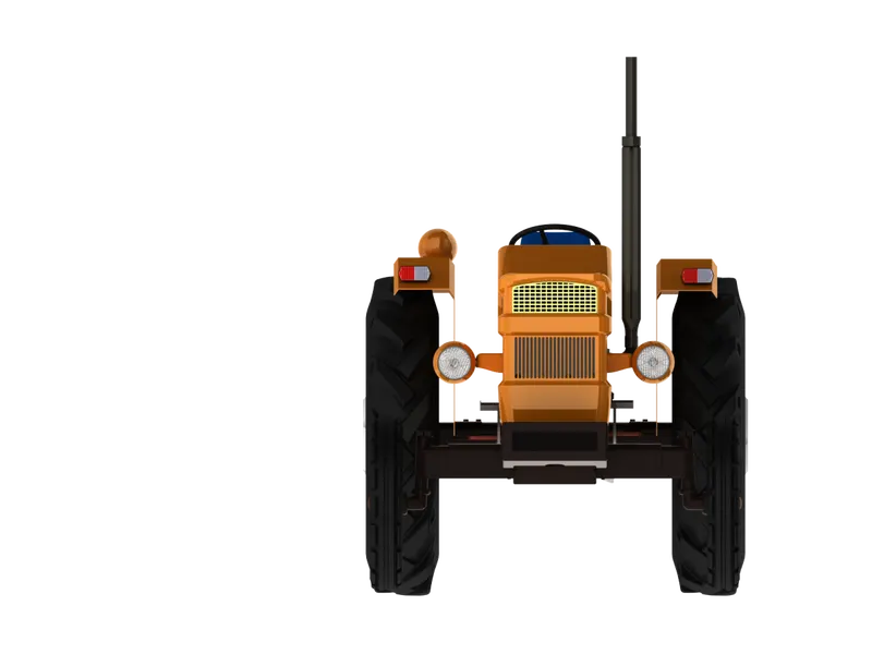
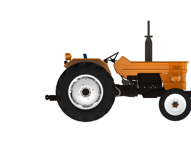
- Render a high quality image using photoview 360 and SolidWorks Visualize.
Software Used:
SolidWorks 2020
- SolidWorks is a parametric modeling software used for making/Designing models in industries such as automobile, aerospace, etc. The software is parametric, which means the model can be altered or modified at any given time. The design of the model changes with the alterations made in the part while modeling.
Motivation for the Project:
- Being an automobile fan I am interested in knowing the working and the design of an automobile. By automobile I also mean various vehicles such as planes, Ships, etc. The most i am interested in is a Tractor. I have liked tractor scenes childhood, and since I got to learn about this course I thought to design a tractorin SolidWorks.
Tools and features used :
- Sketch
- Extruded boss
- Revolved
- Revolved cut
- Swept boss
- Lofted boss
- Boundary boss
- Extrude cut
- Hole wizard
- Revolved cut
- Swept cut
- Loft cut
- Boundary cut
- Fillet
- Chamfer
- Linear patten
- Sketch patten
- circular patten
- mirror
- shell
- dome
- 3Dsketch
- wrap
- Appearances
Part Modeled :
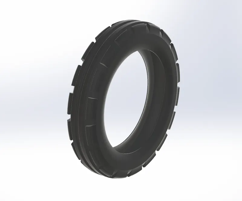
Front Tire :
- An example of tractor tire sizes expressed in the standard format would be “14.9-42”. The “14.9” means the tire is 14.9 inches wide and the “42” tells us that this tire fits a 42-inch diameter wheel. The dash indicates the tire construction is bias-ply, but this could be an “R” if the tire is radial
Tools and features used :
- Revolved
- circular patten
- mirror
Part Image
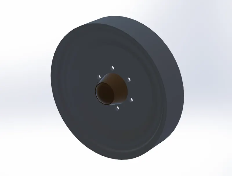
Front Rim
- The truth is that "rims" are actually just one part of the wheel. It is the outer edge of the wheel which holds the tire. It is the outer circular design and surrounds the decorative area of the wheel's hub and spokes. The tire's edges actually lay against the rim, specifically the tire bead.
Tools and features used :
- Extrude cut
- Revolved
Part Image
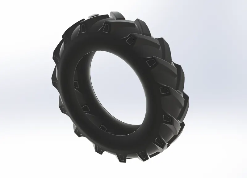
Rear Tire
Tools and features used :
- Revolved
- Revolved cut
- plane
- fillet
- Extrude cut
- loft
- shell
Part Image
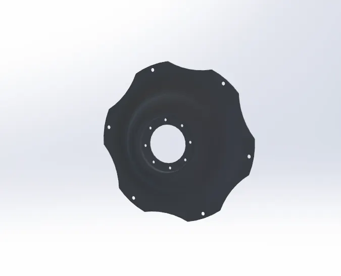
Rear Wheel Hub
Tools and features used :
- Extrude cut
- Revolved
Part Image
Rear Wheel Circle
Tools and features used :
- Extruded boss
- fillet
- circular patten
Part Image
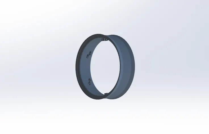
Rear Wheel Weight
Tools and features used :
- Extrude cut
- Revolved
- fillet
Part Image
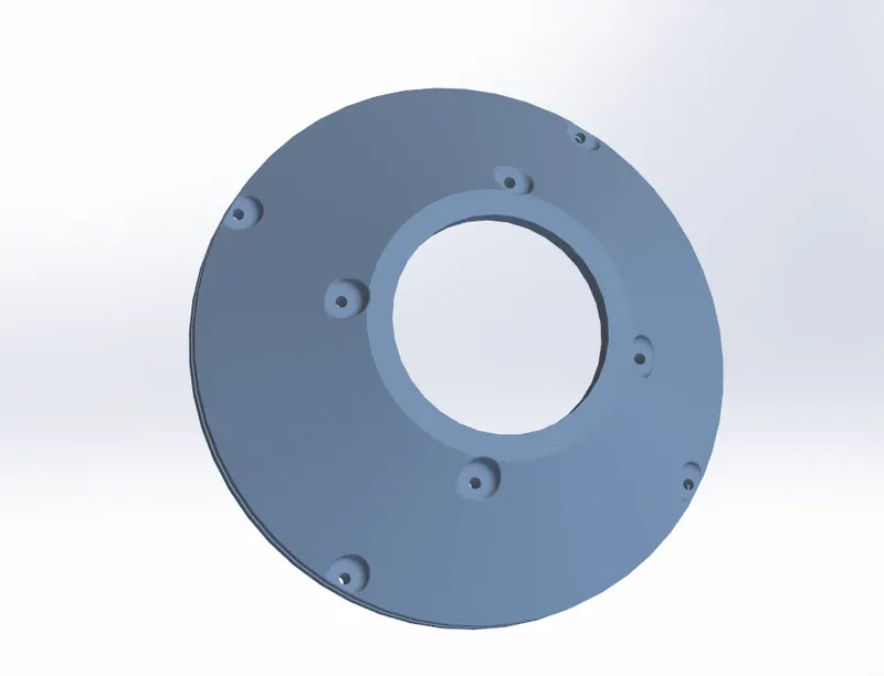
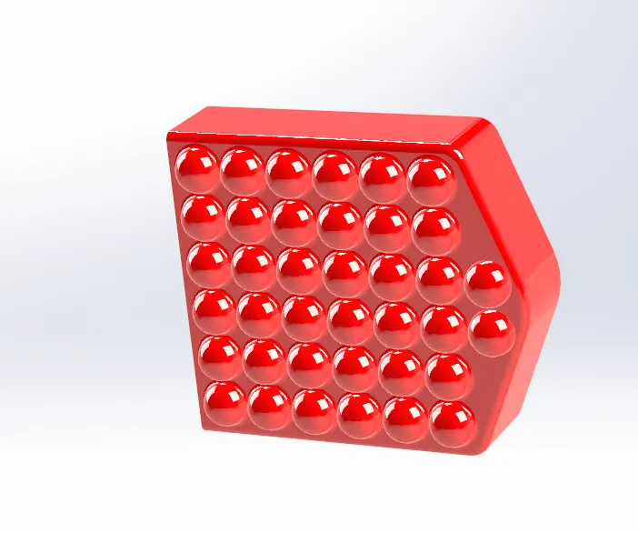
Stop Lamb
Tools and features used :
- Extruded boss
- Extrude cut
- shell
- Revolved
- Revolved cut
- Linear patten
- Sketch patten
- fillet
Part Image
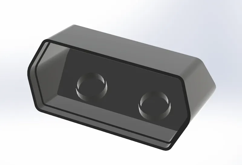
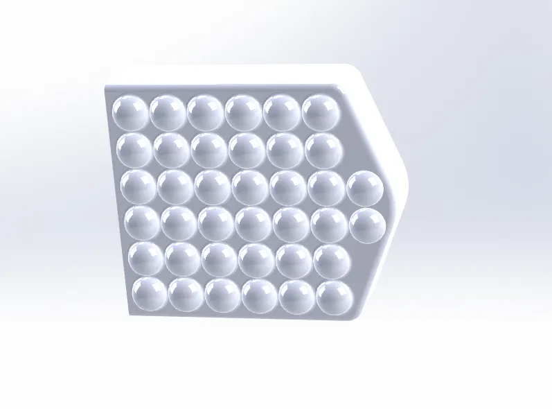
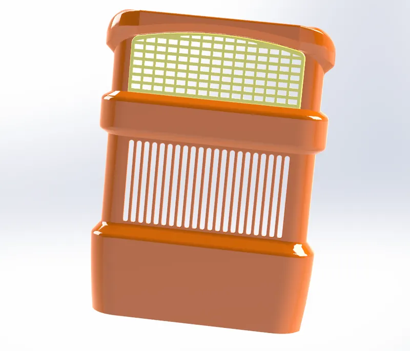
Front Grille
Tools and features used :
- Extruded boss
- Extrude cut
- shell
- wrap
- fillet
- boundaty
- loft
- chamfer
- sweep cut
Part Image
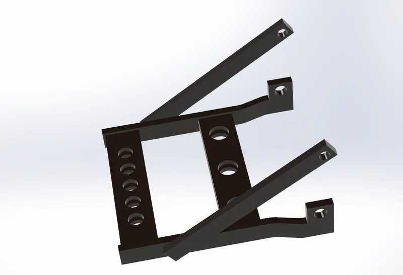
Rear Pull Table
Tools and features used :
- Extruded boss
- Extrude cut
- mirror
- Revolved
Part Image
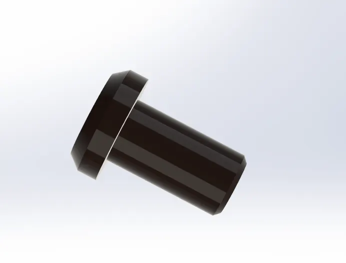
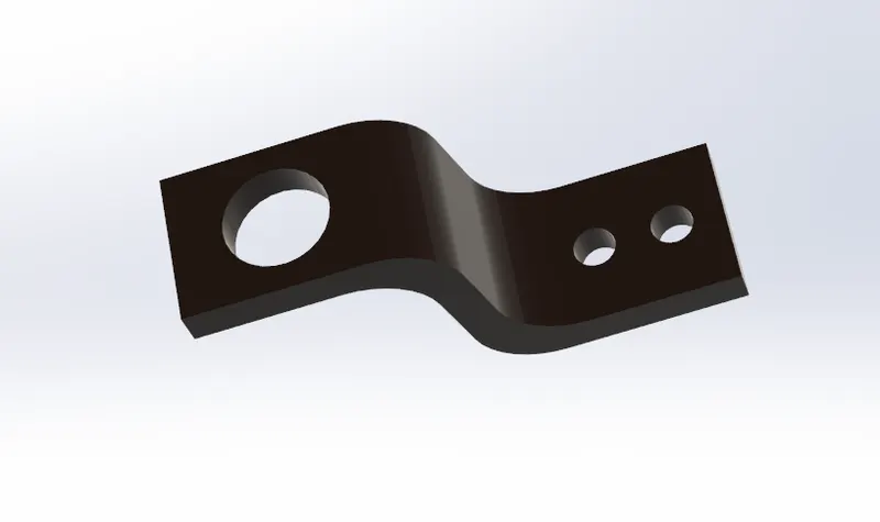
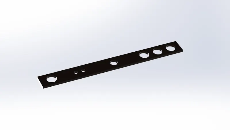
Brake pedal
Tools and features used :
- Extruded boss
- Extrude cut
Part Image
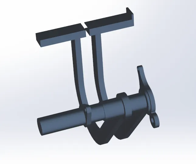
Differential Housing
Tools and features used :
- Extruded boss
- Extrude cut
- shell
- fillet
- boundaty
- chamfer
Part Image
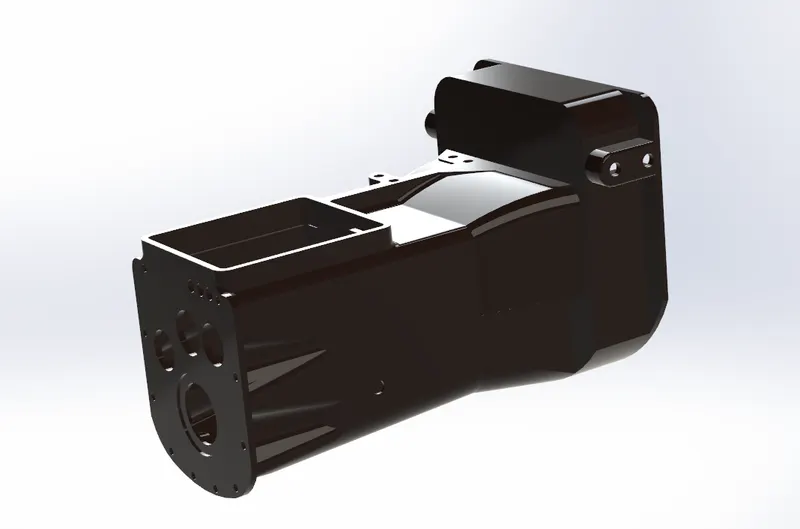
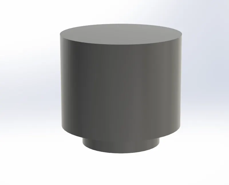
Yan Kovan
Tools and features used :
- Extruded boss
- fillet
- Extruded cut
- tap drill
Part Image
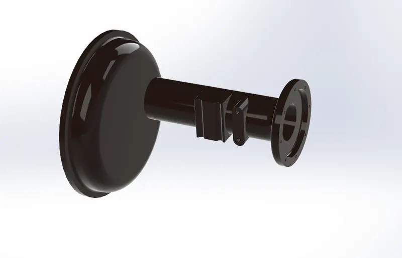
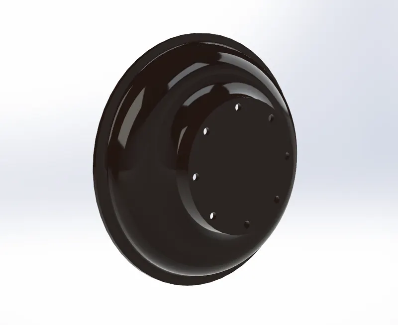
Differential Rear Cover
Tools and features used :
- Extruded boss
- Extrude cut
- fillet
- Revolved
- mirror
Part Image
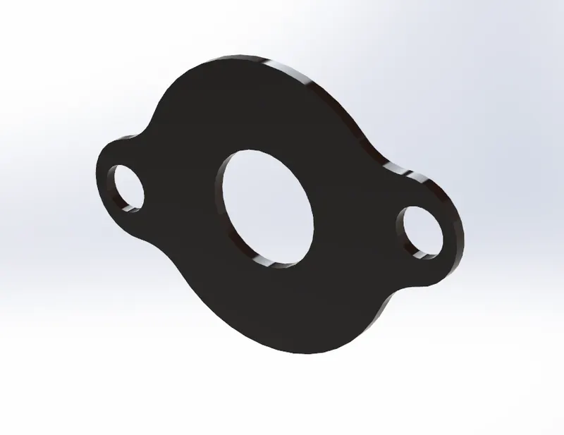
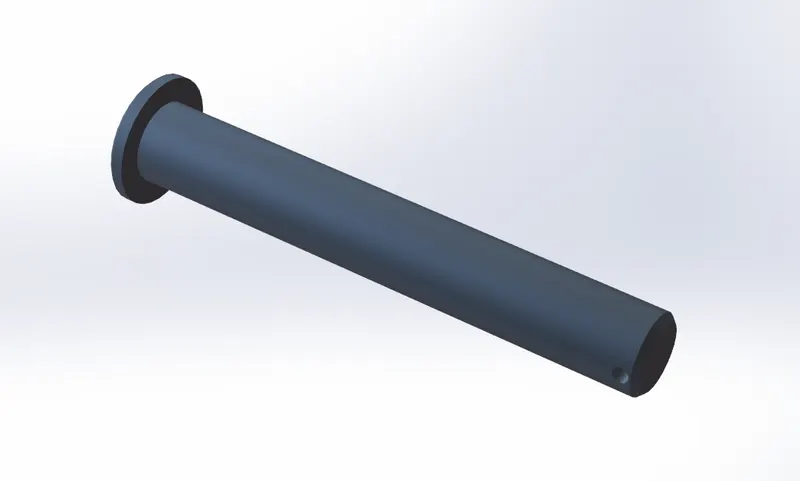
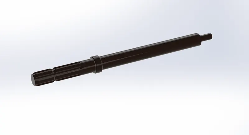
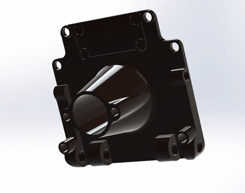
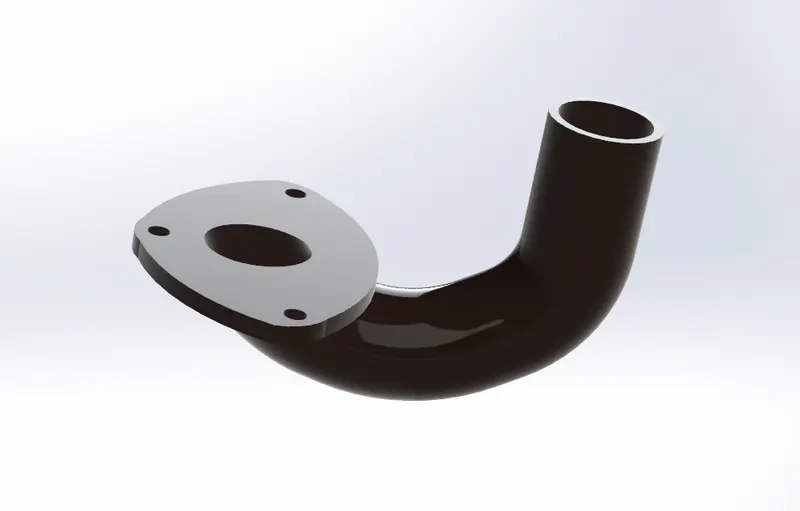
Exhaust
Tools and features used :
- Extruded boss
- Extrude cut
- fillet
- mirror
- sweep
- loft
- sweep cut
Part Image
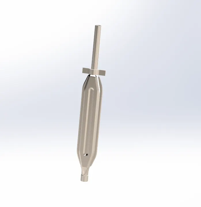
Far
Tools and features used :
- Extruded boss
- Revolve
Part Image
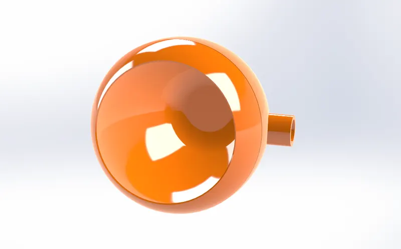
Freni
Tools and features used :
- Extruded boss
- Revolve
- circular patten
- dome
- sweep
Part Image
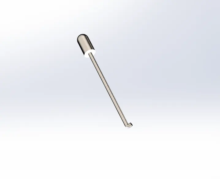
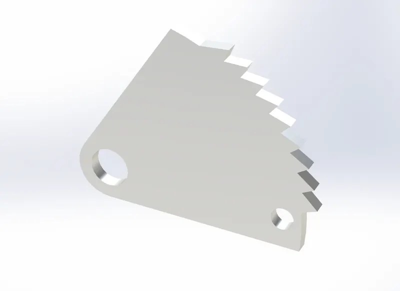
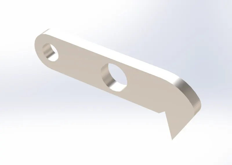
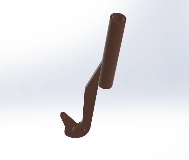
Headlight In
Tools and features used :
- Revolve
- wrap
- fillet
- Extruded boss
Part Image
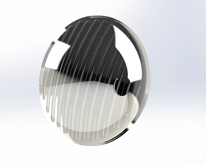
Exhaust Manifold
Tools and features used :
- fillet
- Extruded boss
- boundary
Part Image
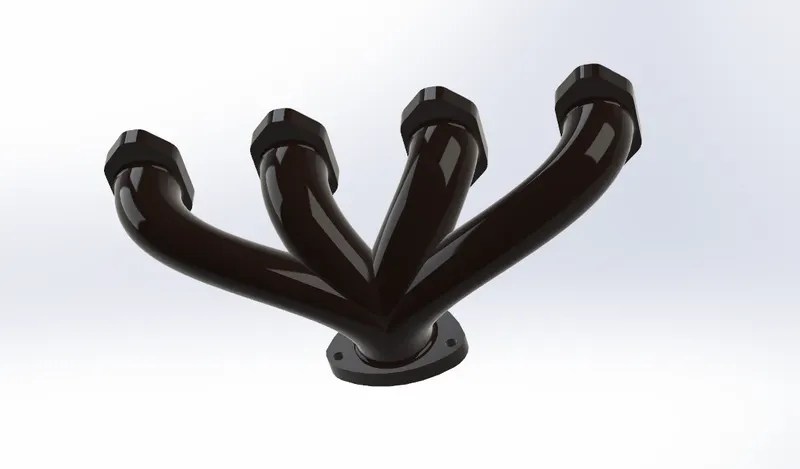
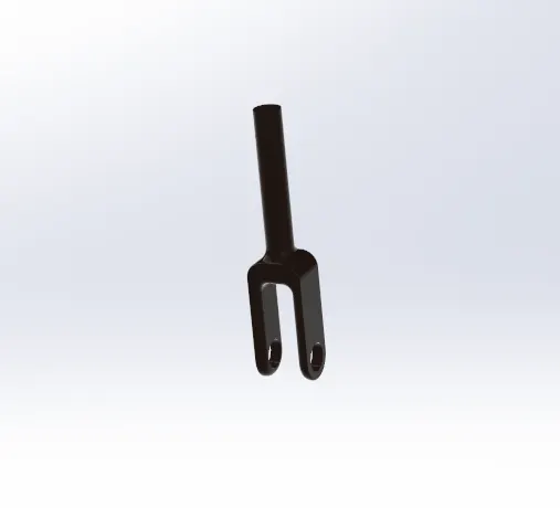
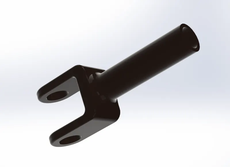
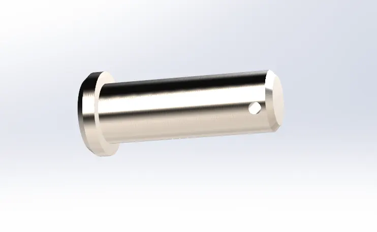
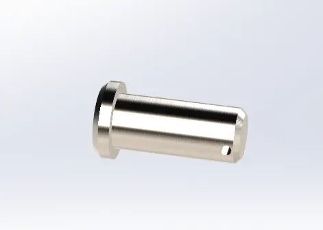
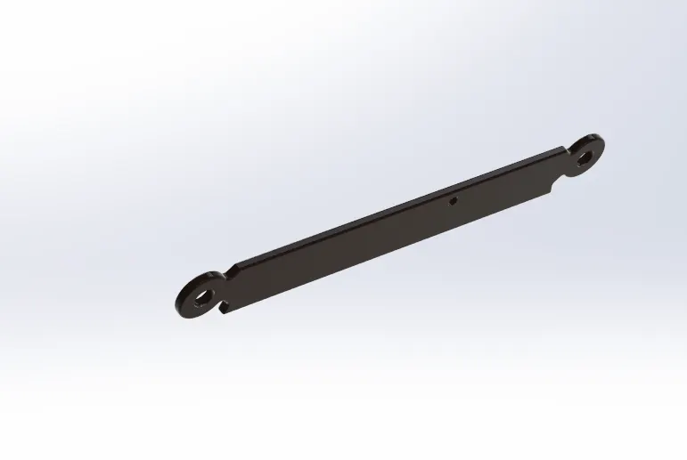
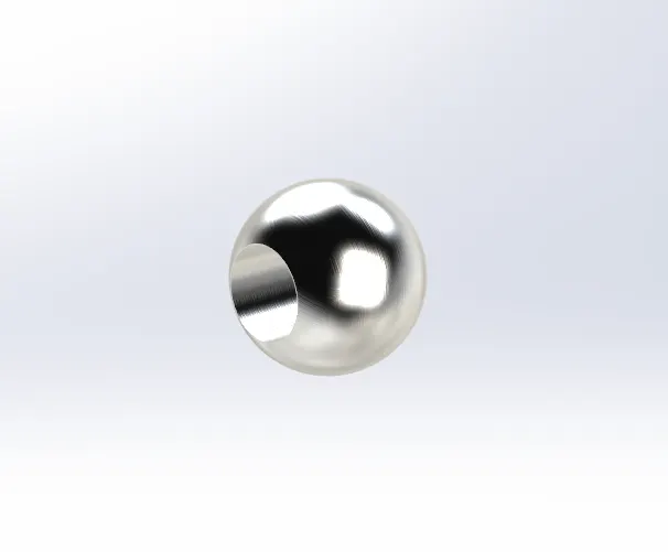
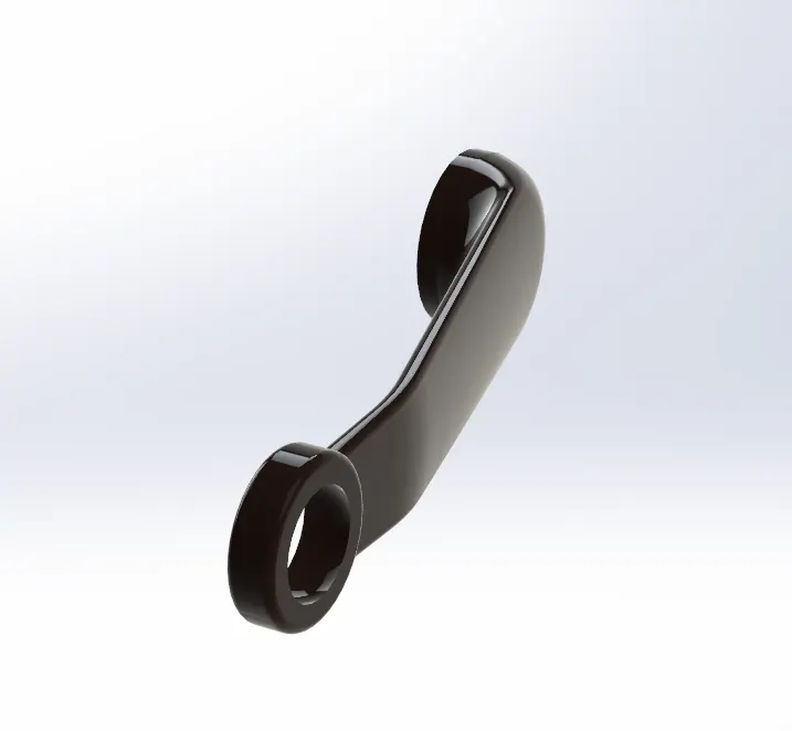
Rear Linkages
Tools and features used :
- Extruded boss
- Extrude cut
- fillet
- Revolve
- mirror
- Revolve cut
- loft
Part Image
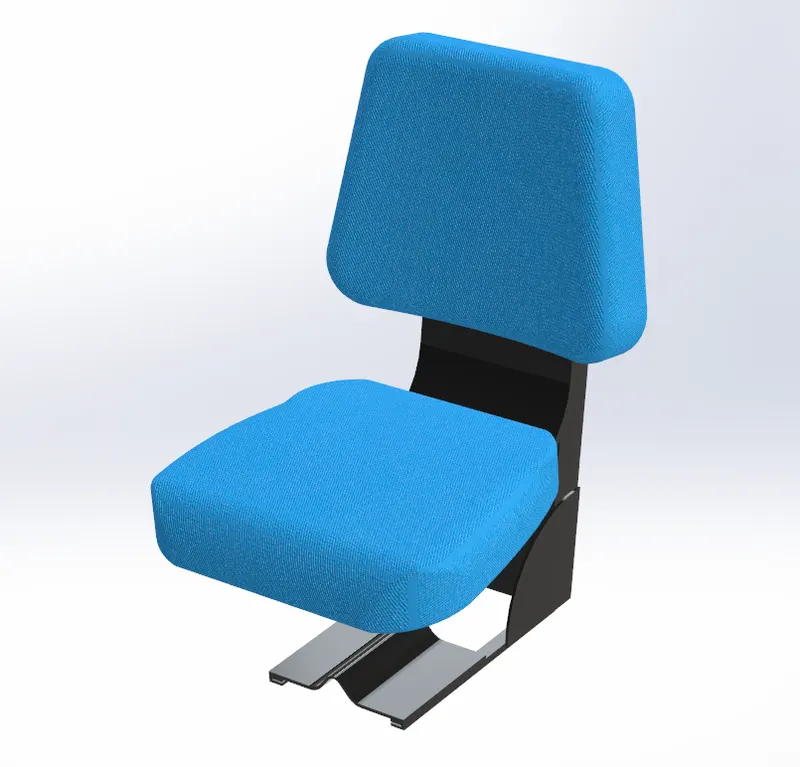
Seat
Tools and features used :
- Extruded boss
- Extrude cut
- fillet
- mirror
Part Image
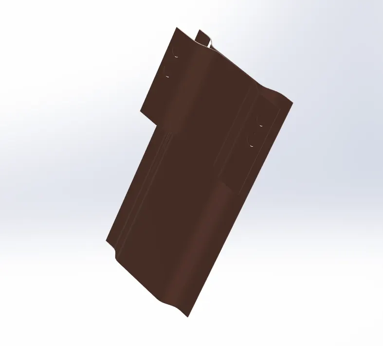
Kaporta
Tools and features used :
- Extruded boss
- Extrude cut
- fillet
- mirror
- shell
Part Image
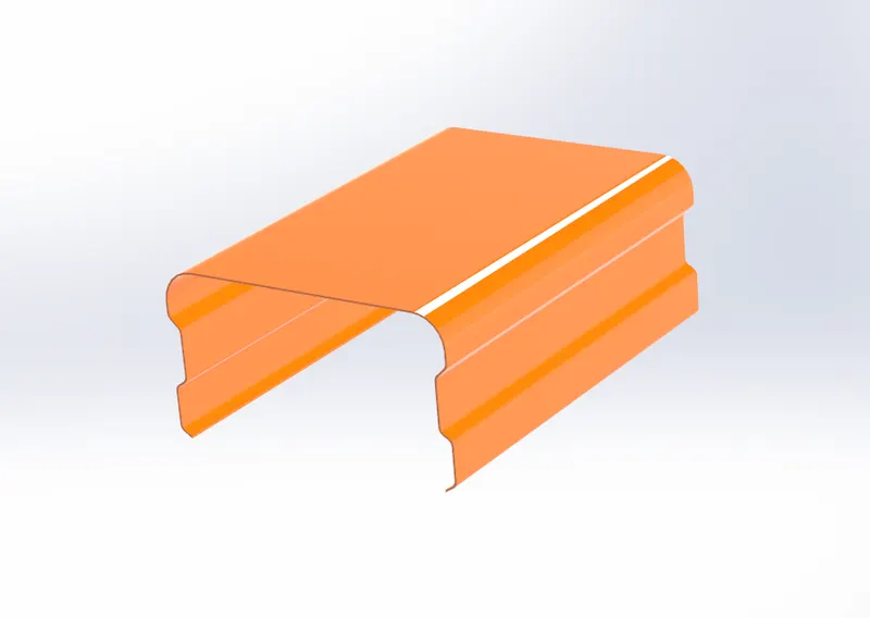
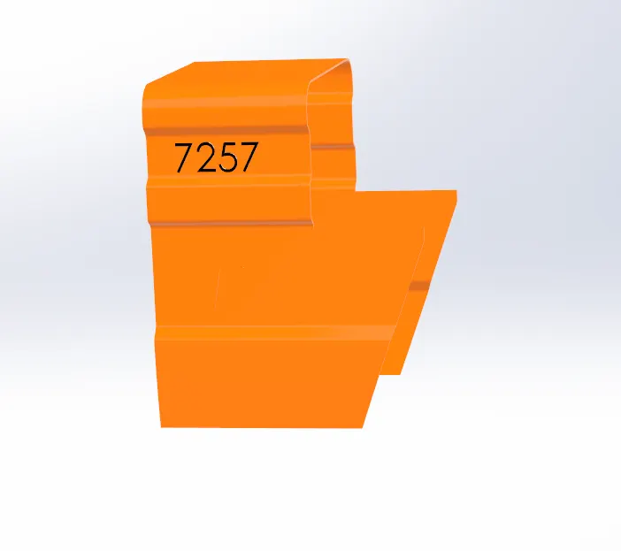
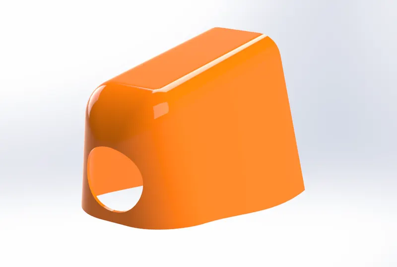
Front Weight Assembly
Tools and features used :
- Extruded boss
- Extrude cut
- fillet
- Revolve
- mirror
- chamfer
- loft
Part Image
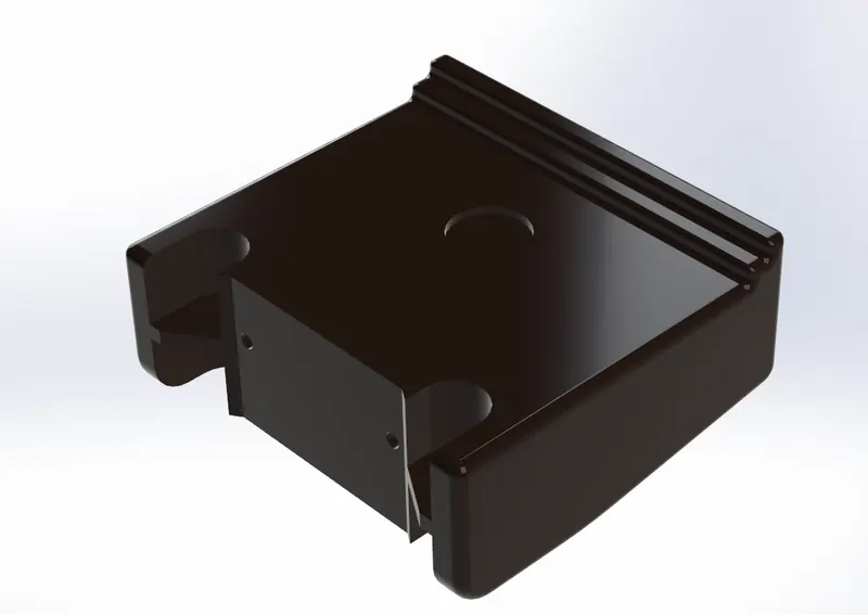
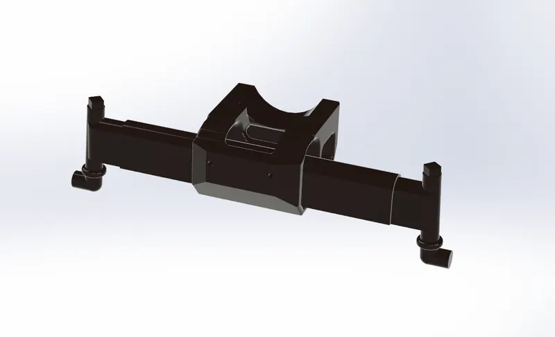
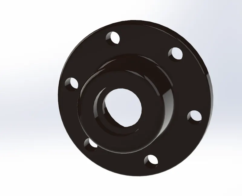
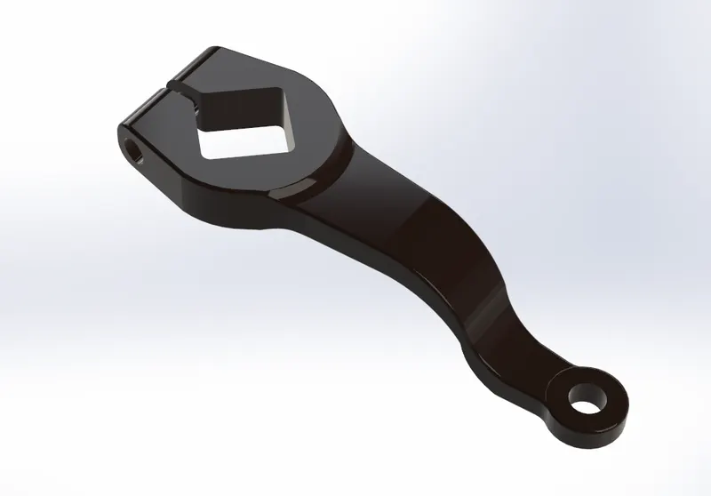
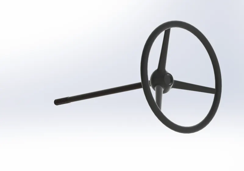
Steering Wheel
Tools and features used :
- Extruded boss
- Extrude cut
- fillet
- Revolve
- circular pattern
- sweep
- Helix
- loft
- mirror
Part Image
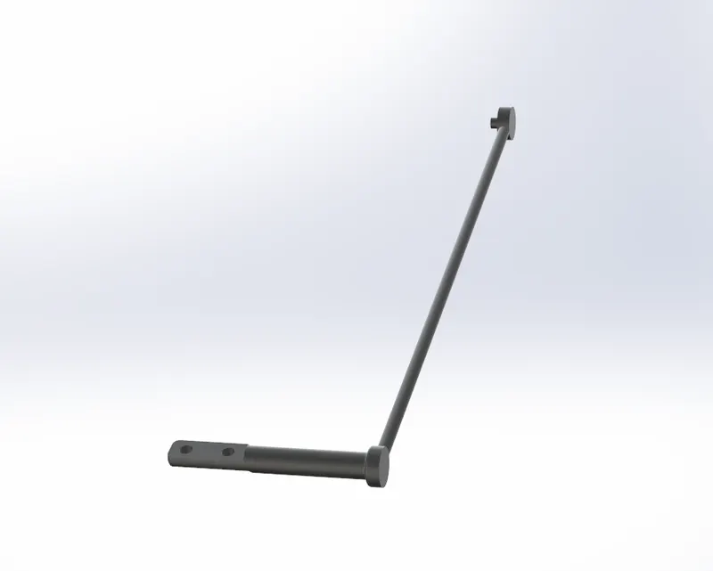
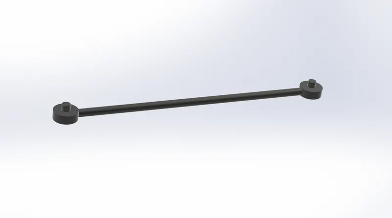
Quick gear
Tools and features used :
- Revolve
- sweep
- Extruded boss
- fillet
- loft
- shell
Part Image
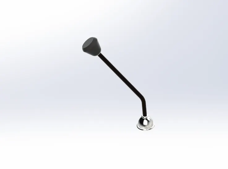
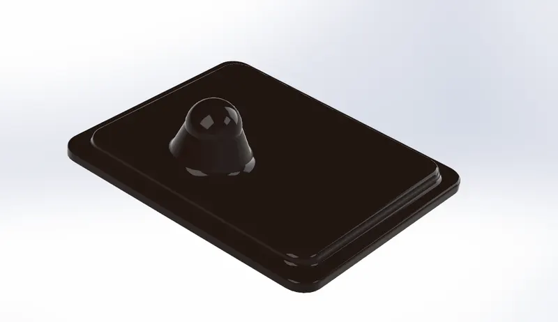
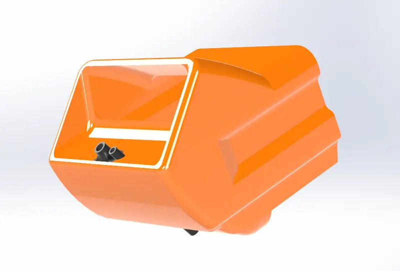
Diesel Tank Top Cowl
Tools and features used :
- Extruded boss
- Extrude cut
- fillet
- sweep
- chamfer
- shell
- Revolve
Part Image
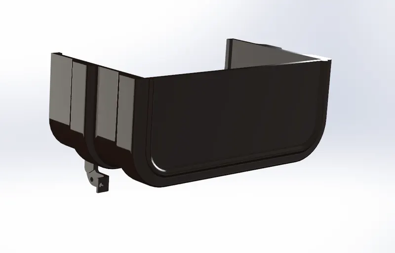
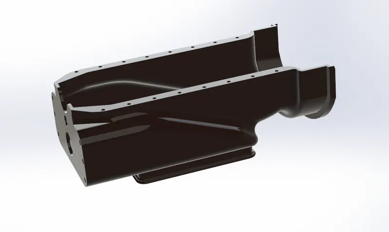
Oil Sump
Tools and features used :
- Extruded boss
- Extrude cut
- fillet
- chamfer
Part Image
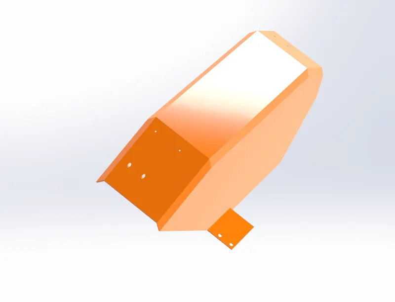
Rear fender
Tools and features used :
- Extruded boss
- Extrude cut
- sweep
Part Image
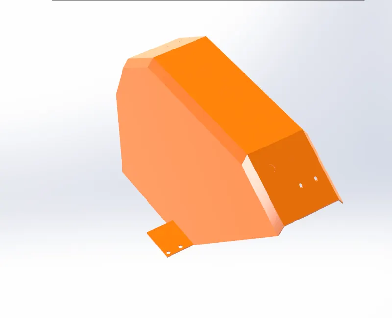
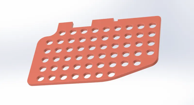
Transmission Housing
Tools and features used :
- Fillet
- Chamfer
- mirror
- Extruded boss
- Extrude cut
- tap drill
- boundary
Part Image
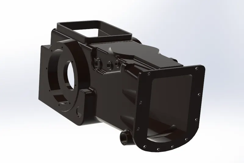
Dashboard
Tools and features used :
- Extruded boss
- Extrude cut
- fillet
- chamfer
Part Image
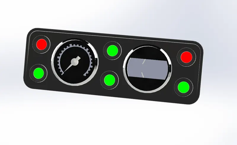
Damper
Tools and features used :
- Extruded boss
- Extrude cut
- fillet
- chamfer
- Revolve
- shell
- mirrort
Part Image
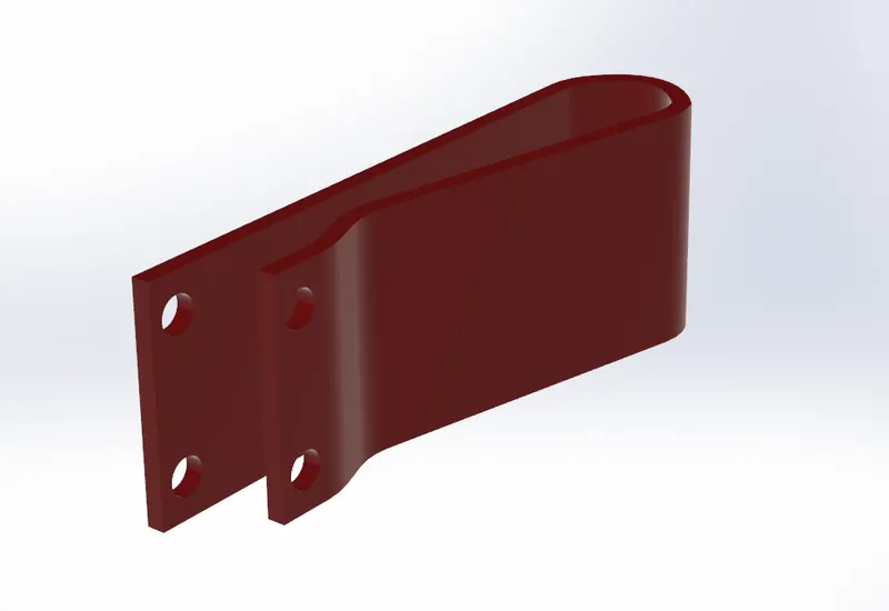
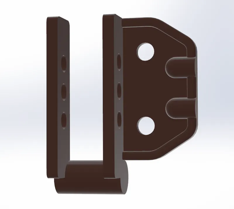
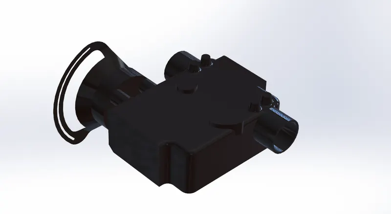
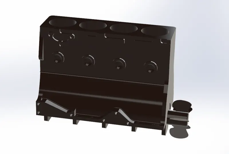
Engine Cylinder Block
Tools and features used :
- Fillet
- Chamfer
- Linear patten
- circular patten
- Extruded boss
- Extrude cut
- Revolve
- mirror
Part Image
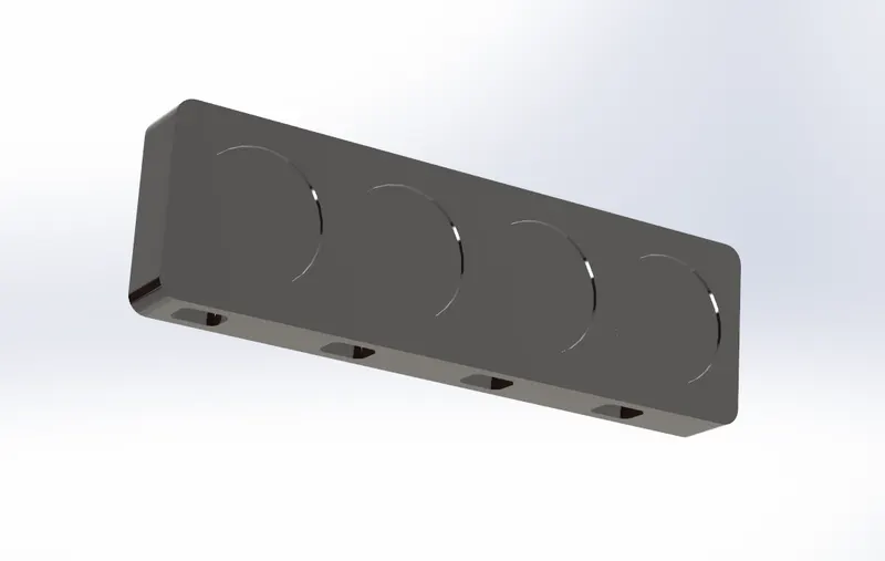
Battery
Tools and features used :
- Extruded boss
- fillet
Part Image
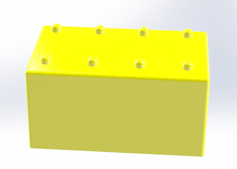
Radiator
Tools and features used :
- Extruded boss
- Extrude cut
- fillet
Part Image
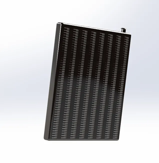
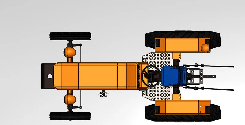
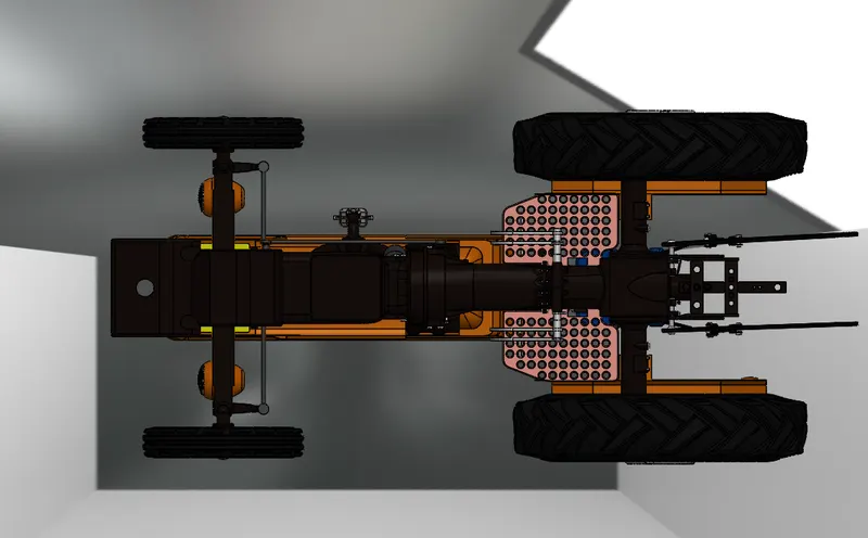
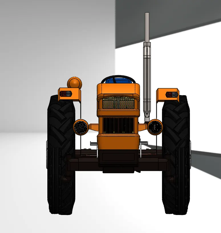
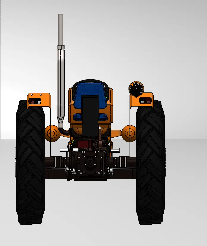
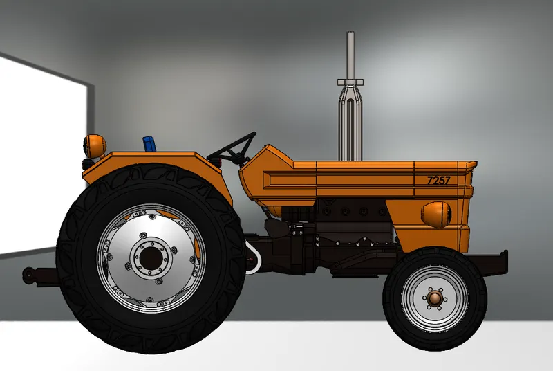
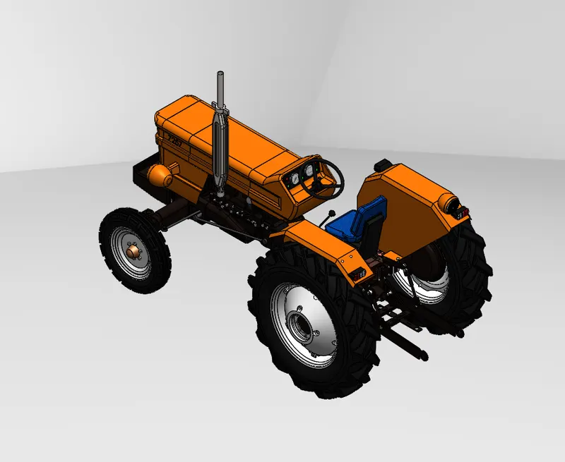
Assembly of the Tractor
- The tractor is assembled in the solidworks assembly. Various mates are used to construct the tractor.
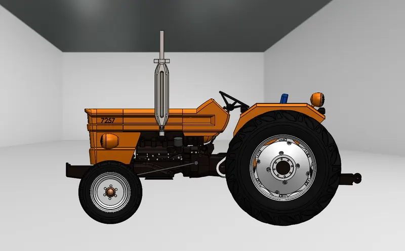
Rendering photorealistic image using PhotoView 360:
- PhotoView 360 is an image rendering software which is available as an add-in in the solidworks.
Conclusion:
- All the parts were designed in solidworks
- The parts were assembled in the assembly
The assembled tractor was rendered using Photoview 360 as well as SolidWorks Visualize