FINAL INDEPENDENT PROJECT
AIM:
To determine the the Forward Kinematics of a 3R Planar Manipulator using MATLAB.
OBJECTIVE:
To achieve the animation of a 3R robotic arm in method of Forward Kinematics process using MATLAB.
THEORY:
FORWARD KINEMATICS:
Kinematics, branch of physics and a subdivision of classical mechanics concerned with the geometrically possible motion ofa body or system of bodies without consideration of the forces involved.
Forward kinematics refers to the use of the kinematic equations of a robot to compute the position of the end-effector from specified values for the joint parameters.
The kinematics equations of the robot are used in robotics, computer games, and animation.
INCLINATION:
The rate at which the object slides down the surface is dependent upon how tilted the surface is; the greater the tilt of the surface, the faster the rate at which the object will slide down it. In physics, a tilted surface is called an inclined plane.
KINEMATIC EQUATION:
The kinematics equations for the series chain of a robot are obtained using a rigid transformation[Z] to characterize therelative movement allowed at each joint and separate rigid transformation [X] to define the dimensions of each link.
The result is a sequence of rigid transformations alternating joint and link transformations from the base of the chain to its end link, which is equated to the specified position for the end link,
[T] = [Z1][X1][Z2][X2]…[Xn-1][Zn].
Where [T] is the transformation locating the end-link. These equations are called the kinematics equations of the serial chain.
CONFIGURATION (OR) POSE OF THE END EFFECTOR:
In robotics, an end effector is the device at the end of a robotic arm, designed to interact with the environment.
An end effector is a peripheral device that attaches to a robot's wrist, allowing the robot to interact with its task. Most end effectors are mechanical or electromechanical and serve as grippers, process tools, or sensors.
WORKING:
A robotic arm is a type of a mechanical arm, usually programmable, with similar functions to a human arm. The arm may be the sum total of the mechanism (or) may be the part of a more complex robot. The links of such a manipulator are connected by joints allowing either rotational motion (or) translational displacement.
The links of the manipulator can be considered to form a kinematic chain. The terminus of the kinematic chain of the manipulator is called the end effector and it is analogous to the human hand.
Forward kinematics refers to the use of kinematics equations of a robot to compute the position of the end-effector from specified values for the joint parameters.
Robotic arms are used in various industrial applications such as drilling, welding, metal cutting, painting etc...
The link-1 is attached to the base and end of the link one is connected to link-2. End of link-2 is connected to the end effector which performs the desired operation.
The link-2 is attached to the base and end of the link one is connected to link-3. End of link-3 is connected to the end effector which performs the desired operation.
In this challenge we will restrict the movement of the links in 2-D plane.
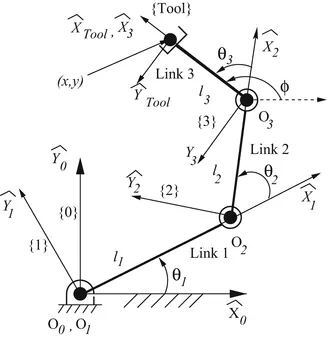
FORWARD KINEMATICS OF 3R PLANAR MANIPULATOR:
Forward Kinematics: From basic trigonometry, the position and orientation of the end effector can be written in terms of the joint coordinates in the following way:
x = l1cos θ1 + l2cos θ (θ1 + θ2) + l3cos(θ1 + θ2 + θ3)
y = l1sin θ1 + l2sin θ (θ1 + θ2) + l3sin(θ1 + θ2 + θ3)
ϕ = (θ1 + θ2 + θ3)
Note that all the angles have been measured counter clockwise and the link lengths are assumed to be positive going from one joint axis to the immediately distal joint axis.
Equation (1) is a set of three nonlinear equations2 that describe the relationship between end effector coordinates and joint coordinates.
Notice that we have explicit equations for the end effector coordinates in terms of joint coordinates. However, to find the joint coordinates for a given set of end effector coordinates (x, y, ϕ ), one needs to solve the nonlinear equations for o1, o2, and o3.
As seen earlier, there are two types of coordinates that are useful for describing the configuration of the system.
If we focus our attention on the task and the end effector, we would prefer to use Cartesian coordinates or end effector coordinates.
The set of all such coordinates is generally referred to as the Cartesian space or end effector space3 . The other set of coordinates is the so called joint coordinates that is useful for describing the configuration of the mechanical linkage.
The set of all such coordinates is generally called the joint space.
In robotics, it is often necessary to be able to “map” joint coordinates to end effector coordinates. This map or the procedure used to obtain end effector coordinates from joint coordinates is called direct kinematics.
For the 3-R manipulator, the procedure reduces to simply substituting the values for the joint angles in the equations
x = l1cos θ1 + l2cos θ (θ1 + θ2) + l3cos(θ1 + θ2 + θ3)
y = l1sin θ1 + l2sin θ (θ1 + θ2) + l3sin(θ1 + θ2 + θ3)
ϕ = (θ1 + θ2 + θ3)
and determining the Cartesian coordinates, x, y and ϕ.
On the other hand, the same procedure becomes more complicated if the mechanism contains one or more closed loops.
In addition, the direct kinematics may yield more than one solution or no solution in such cases. For a Stewart Platform, this number has been shown to be anywhere from zero to forty.
MAIN PROGRAM:
clear all
close all
clc

%Inputs
a1 = 1;
a2 = 0.75;
a3 = 0.5;
ct = 1;

theta1DegMin = 30;
theta2DegMin = 60;
theta3DegMin = 90;

theta1DegMax = 60;
theta2DegMax = 90;
theta3DegMax = 120;

theta1Min = theta1DegMin*pi/180;
theta2Min = theta2DegMin*pi/180;
theta3Min = theta3DegMin*pi/180;


theta1Max = theta1DegMax*pi/180;
theta2Max = theta2DegMax*pi/180;
theta3Max = theta3DegMax*pi/180;

noOfSteps = 50;
deltaTheta1 = (theta1Max-theta1Min)/noOfSteps;
deltaTheta2 = (theta2Max-theta2Min)/noOfSteps;
deltaTheta3 = (theta3Max-theta3Min)/noOfSteps;


theta1 = theta1Min;
theta2 = theta2Min;
theta3 = theta3Min;


%calculations
aXArray = zeros(noOfSteps,1);
aYArray = zeros(noOfSteps,1);
bXArray = zeros(noOfSteps,1);
bYArray = zeros(noOfSteps,1);
cXArray = zeros(noOfSteps,1);
cYArray = zeros(noOfSteps,1);

for i = 1:1:noOfSteps
    ax = a1*cos(theta1);
    ay = a1*sin(theta1);
    bx = ax + a2*cos(theta1 + theta2);
    by = ay + a2*sin(theta1 + theta2);
    cx = bx + a3*cos(theta1 + theta2 + theta3);
    cy = by + a3*sin(theta1 + theta2 + theta3);
    phi = theta1 + theta2 + theta3;
    phiDeg = phi*180/pi;

    aXArray(i) = ax;
    aYArray(i) = ay;
    bXArray(i) = bx;
    bYArray(i) = by;
    cXArray(i) = cx;
    cYArray(i) = cy;

    theta1 = theta1 + deltaTheta1;
    theta2 = theta2 + deltaTheta2;
    theta3 = theta3 + deltaTheta3;
end

xAxisArrayXCoords = [-2 2];
xAxisArrayYCoords = [0 0];

yAxisArrayXCoords = [0 0];
yAxisArrayYCoords = [-2 2];


%Animation

for i = 1:1:noOfSteps
    ax = aXArray(i);
    ay = aYArray(i);
    bx = bXArray(i);
    by = bYArray(i);
    cx = cXArray(i);
    cy = cYArray(i);

    link1XCoords = [0 ax];
    link1YCoords = [0 ay];

    link2XCoords = [ax bx];
    link2YCoords = [ay by];

    link3XCoords = [bx cx];
    link3YCoords = [by cy];
    plot(xAxisArrayXCoords, xAxisArrayYCoords,'r',yAxisArrayXCoords, yAxisArrayYCoords, 'c');
    hold on
    plot(link1XCoords, link1YCoords, 'g', link2XCoords, link2YCoords,'y',link3XCoords, link3YCoords, 'b' );
    pause(0.10);


    M(ct) = getframe(gcf);
    ct = ct + 1;
    hold off;
end


% Making movie from collected frames
movie(M)

% creating a video file of '.avi' format to save the animation
videofile = VideoWriter('Forward_kinematics_of_3R_planar_manipulator.avi','Uncompressed AVI');
open(videofile)

writeVideo(videofile, M)
close(videofile)
PROGRAM EXPLANATION:
1.Starting the process with clc commands.
2.Input variables are declared as per our projection.
3.Angles traced by both the links, for link-1,link-2 and link-3 is taken as input. The angles are traced are varied over a range to simulate the movement of the robotic arm.
4.For each particular angle of link-1,link-2 and link-3 is moved over its entire range, to obtain different positions of end effector at that angel of link-1 and link-2.
5.ThetaMinimum(ThetaMin) and ThetaMaximum(ThetaMax) degrees are declared as per our requirement.
6.Defining the formulae sector in the program for theta1Min,theta2Min,theta3Min and theta1Max,theta2Max,theta3Max respctively to produce the progress of program.
7. Deltatheta values are gets formulated to calculate the Deltatheta value with respect to 1,2,3.
8.In calculation part aXArray,aYArray, bXArray,bYArray, cXArray,cYArray are assigned.
9.In next step we formulated the ax, ay, bx, by, cx, cy terms.
10.phi and phiDeg is declared to the projecting the angles.
11.The calculation done as per formulae:
ax = a1*cos(theta1);
ay = a1*sin(theta1);
bx = ax + a2*cos(theta1 + theta2);
by = ay + a2*sin(theta1 + theta2);
cx = bx + a3*cos(theta1 + theta2 + theta3);
cy = by + a3*sin(theta1 + theta2 + theta3);
phi = theta1 + theta2 + theta3;
phiDeg = phi*180/pi; respcetively.
12.In animation part the link1 link2 link3 with respect to X and Y coords are plotted.
13.In Next step we Making movie from collected frames.
14.Creating a video file in ".avi" format to save the animation output.
ERRORS MADE WHILE PROGRAMMING:
1.
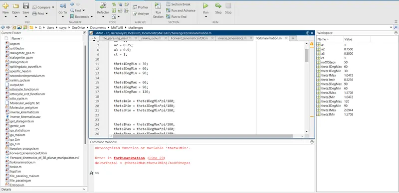
Here i declared function wrongly and i rectified my error.
2.

Some Typo errors are made by seeing command window i rectified the errors.
OUTPUT:
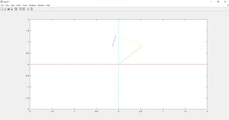
1.The final image of an animated 3R planar manipulator:
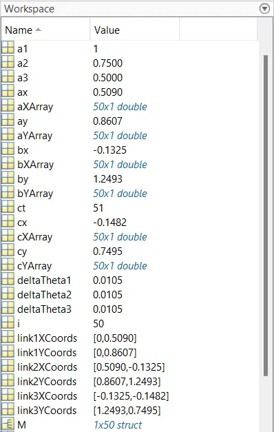
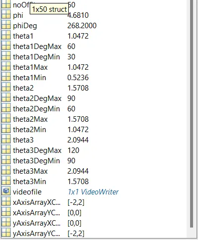
2.Work Space Answers:
OBSERVATION:
Thus the animation of a 3R robotic arm in method of Forward Kinematics process using MATLAB is obtained.
YOUTUBE LINK: https://youtu.be/s2nS3jadICE
RESULT:
Thus the Forward Kinematics of a 3R Planar Manipulator using MATLAB is processed sucessfully.
REFERENCE:
1.https://www.sciencedirect.com/topics/engineering/forward-kinematics
2.https://www.cs.duke.edu/brd/Teaching/Bio/asmb/current/Papers/chap3-forward-kinematics.pdf
3.https://www.researchgate.net/figure/The-planar-3R-manipulator_fig3_286842602
4.https://www.slideshare.net/DamianGordon1/forward-kinematics