FINAL INDEPENDENT PROJECT
PROJECT REPORT
TITLE: MODELING AND RENDERING OF FORKLIFT IN SOLIDWORKS
OBJECTIVE: To design and model the parts of the Forklift, assembling the parts to get the final product and finally rendering it to give it a nice finished look.
INTRODUCTION: A Forklift is a powered industrial truck used to move materials over short distances. Forklifts are rated for loads at a specified maximum weight. The parts are designed, modelled and assembled in "Solidworks 2015". It is a 3D CAD and CAE Software built by Dassault Systémes . The rendering of the model is done in Photoview 360 or Solidworks visualise.
DESIGN METHODOLOGY:
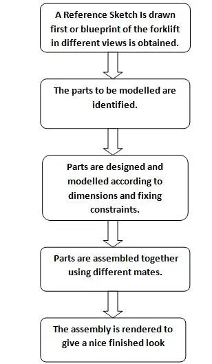
DESCRIPTION:
After the reference sketch is created and idea of the model is generated. The part modelling and designing is done in Solidworks . The Forklift consists of 19 parts. These are as follows:
- Forklift Body
- Driver Seat
- Steering
- Hand Lever
- Hydraulic Cylinder
- Push Rod
- Tyre
- Front Axle
- Rear Axle
- Exhaust
- Air intake manifold
- Front Light
- Rear Light
- Frame Inner
- Frame 2
- Fork Support
- Fork
- Connecting Plate
These parts are created using different tools and features in solidworks and are given appropriate appearances. We will take a look at all these in details.
FORKLIFT BODY:
It is the main supporting part of the forklift. It should be rigid to support the load which is to be lifted by the forklift.
The features used in designing of the forklift body are:
Surface extrude: This feature converts the projected surface into a 3D surface.
Surface Extend: It helps in extending the edge of a surface to the desired length.
Surface trim: It is to consume bodies which are not needed in the model.
Knit Surfaces: This feature is used to bind together all surfaces and combine them as a single surface. In this there is also an option of converting them into solid.
Filled Surface: This feature also creates surface between the boundaries or edges. Specify the edges and it will automatically fill surface between the edges.
Lofted Surface: This feature creates a surface between the edges by creating a smooth tangency between the Selected Curves.
Extrude: It is used to convert our 2D sketch into a 3D model
Mirror: It is a feature used in creating a copy of the feature or sketch about a face or a plane.
Extrude Cut: This Feature allows easy removal of a material from solid by extruding a profile along its normal.
Sweep: This feature is used to create a solid body by moving a closed sketch along a pre defined path.
Fillet: It is to give nice smooth rounding to the hard edges in the model.
Chamfer: This feature allows us to create a sloping surface at the edge or corner of our solid body.
Split line: This feature is used to project the sketch onto the surface our model.
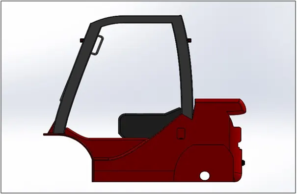
Fig 1. Forklift Body
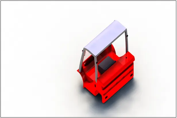
Fig 2. Forklift Body Render Image
DRIVER SEAT:
It is the place from where the operator operates the forklift.
The features used in designing of the driver seat are:
Extrude
Fillet
Sweep
Mirror
Dome: It helps in creating a bulging surface on the faces of the solid models.
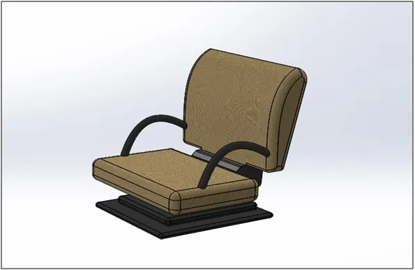
Fig 3. Driver Seat
STEERING:
It is the control which directs the vehicle to move left or right depending upon the drivers requirements.
The features used in designing of the steering are:
Extrude
Extrude Cut
Sweep
Fillet
Mirror
Loft: This feature allows us to create complex geometry in a single feature It does this by interpolating the surfaces of different cross sections.
Circular Pattern: This Feature allows to create multiple instances of the sketch or feature along a circular edge.
Combine: This feature is used to convert different bodies to a single body and also it is used to subtract one body from another if they are intersecting.
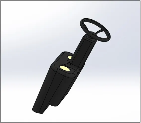
Fig 4. Steering
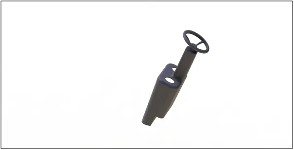
Fig 5. Steering Render Image
HAND LEVER:
The control which the operator uses for the tilting and lifting of the fork and fork support to lift heavy loads.
The features used in designing of the hand lever are:
Extrude
Loft
Sweep
Fillet
Linear Pattern: This Feature is used to create multiple instances of one or more features that can be spaced uniformly along one or two linear paths.
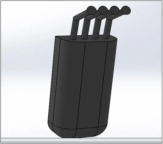
Fig 6. Hand Lever
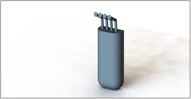
Fig 7. Hand Lever Render Image
HYDRAULIC CYLINDER:
The cylinder works on hydraulic pressure. It is used to tilt the frame for easy lifting of loads.
The features used in designing of the hydraulic cylinder are:
Revolve: This feature is used to create a circular section using a sketch and a centreline along which the sketch is revolved.
Extrude Cut:
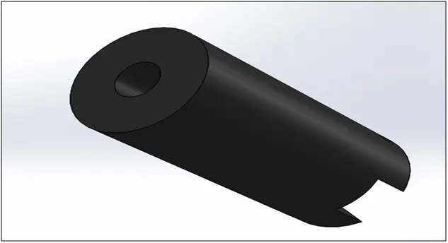
Fig 8. Hydraulic Cylinder
PUSH ROD:
As the name suggests it is used for pushing the frame to tilt it. It is fitted in the hydraulic cylinder.
The Features used in designing of the push rod are:
Revolve
Extrude Cut
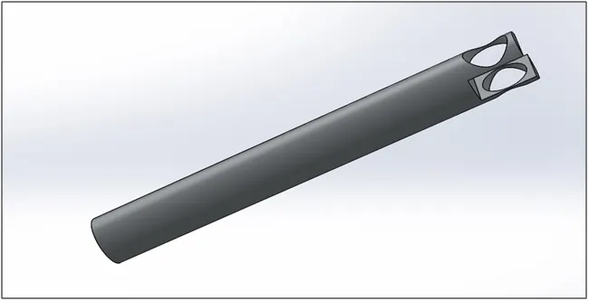
Fig 9. Push Rod
TYRE:
Forklift front tyres are tubeless tyres and usually bigger in size than the rear tyres to support the heavy load which is lifted by the fork at the front. The rear tyres help in maneuvering the forklift in the left or right directions.
The features used in designing of the front tyres are:
Revolve
Extrude
Fillet
Circular Pattern
Combine
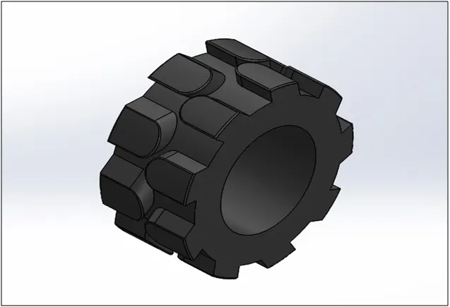
Fig 10. Tyre
FRONT AXLE:
Front axle consists of a differential and supports the two front tyres.
The features used in designing of the front axle are:
Extrude
Fillet
Circular Pattern
Mirror
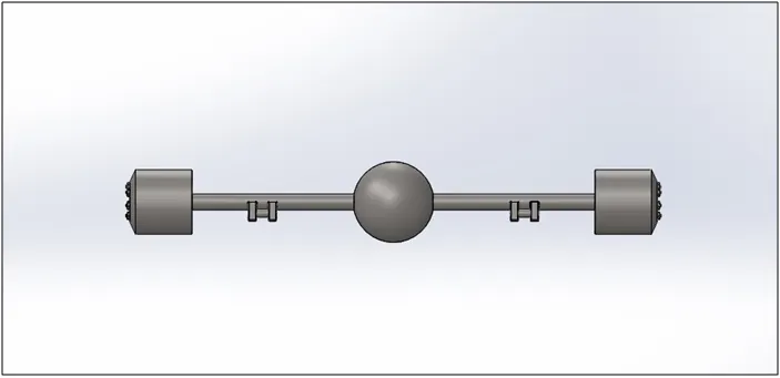
Fig 11. Front Axle
REAR AXLE:
It is fitted at the rear end of the forklift and supports the rear tyres.
The features used in designing of the front axle are:
Extrude
Fillet
Circular Pattern
Mirror
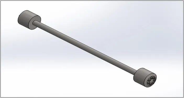
Fig 12. Rear Axle
EXHAUST:
The exhaust from the engine is released to the open air through this exhaust manifold.
The features used in designing of the front axle are:
Revolve
Extrude
Extrude Cut
Sweep
Sweep Cut: It is used to cut a solid body by a closed sketch along a definite path
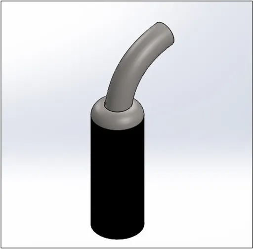
Fig 13. Exhaust
AIR INTAKE MANIFOLD:
The fresh air for the engine is taken in from the atmosphere through this manifold. The air passes through the filter and into the engine.
The features used in designing of the air intake manifold are:
Revolve
Extrude
Extrude Cut
Sweep
Fillet
Circular Pattern
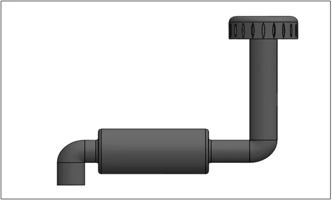
Fig 14. Air intake manifold
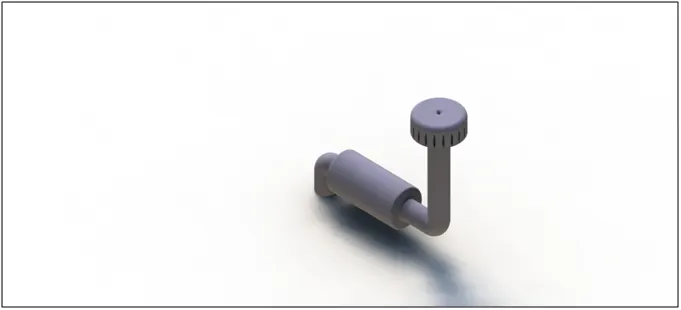
Fig 15. Air intake manifold render image
FRONT LIGHT:
The features used in designing of the front lights are:
Extrude
Chamfer: This feature allows us to create a sloping surface at the edge or corner of our solid body.
Fillet
Extrude Cut
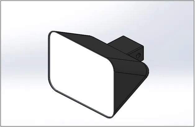
Fig 16. Front Light
REAR LIGHT:
The features used in designing of the rear lights are:
Extrude
Fillet
Extrude Cut
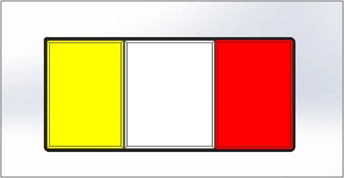
Fig 17. Rear Light
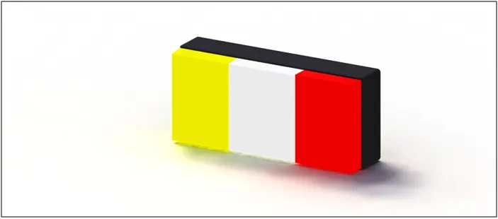
Fig 18. Rear Light Render Image
FRAME INNER:
The features used in designing of frame 1 are:
Extrude
Linear Pattern
Fillet
Extrude Cut
Mirror
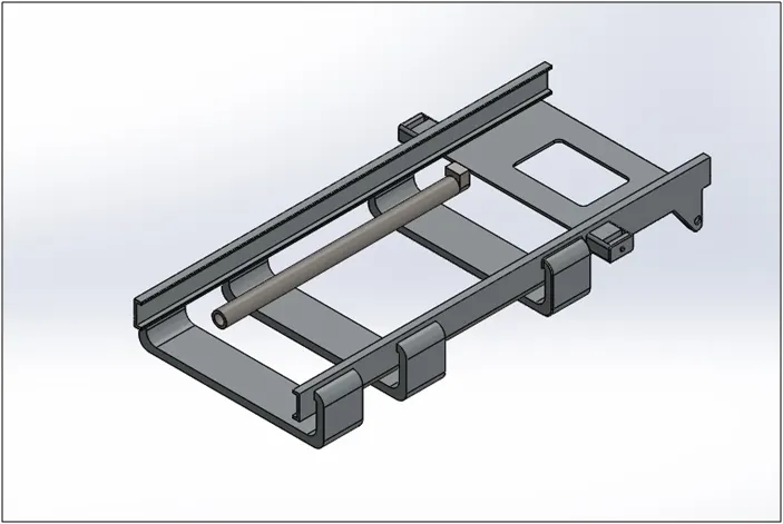
Fig 19. Frame inner
FRAME 2:
Frame 2 slides up and down with respect to frame 1. It decides the height upto which the load has to be lifted.
The features used in designing of frame 2 are :
Extrude
Linear Pattern
Mirror
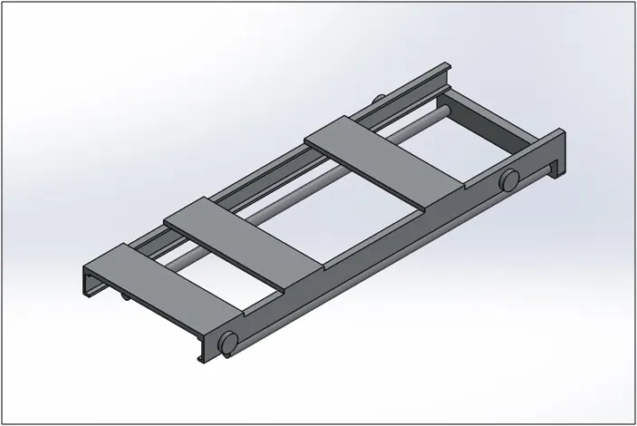
Fig 20. Frame 2
FORK SUPPORT:
It supports the fork and is connected to the frame 2.
The features used in designing of the fork support are:
Extrude
Fillet
Linear pattern
Extrude Cut
Mirror
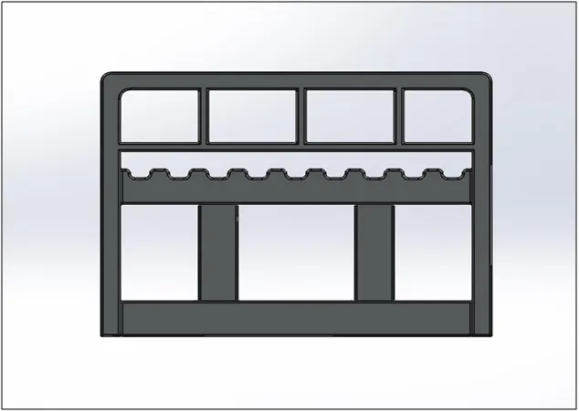
Fig 21. Fork Support
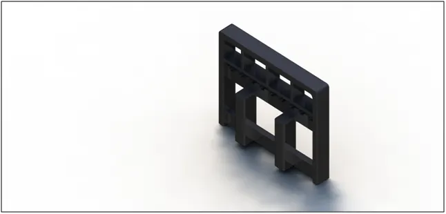
Fig 22. Fork Support Render Image
FORK:
The fork is used to lift heavy loads.
The Features used in designing of forks are:
Extrude
Fillet
Extrude Cut
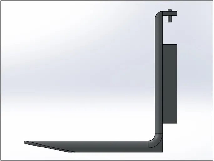
Fig 23. Fork
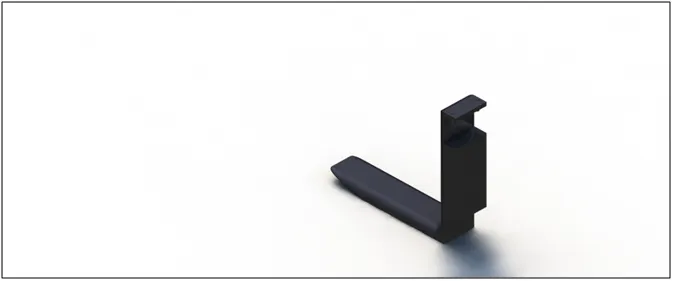
Fig 24. Fork
CONNECTING PLATE:
This plate is used to connect the hydraulic cylinders to the forklift body.
The features used in designing of the connecting plate are:
Extrude
Fillet
Mirror
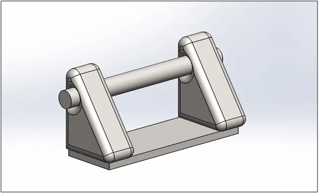
Fig 25. Connecting plate
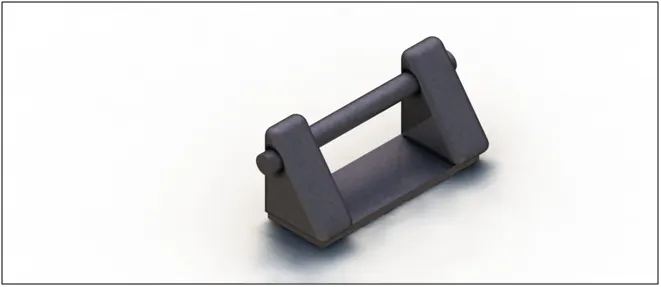
Fig 26. Connecting Plate render image
ASSEMBLING OF FORKLIFT:
After the part designing and modelling and giving suitable appearance to the parts comes the next step of assembling all the parts to make our final product.
The assembly is done in the assembly file of solidworks. The components are inserted one by one and different mates are applied to fix them. The forklift body is taken as the reference.
Some of the mates used in this project are mentioned below:
Concentricity
Coincident
Width Mate
Angle mate
Parallel mate
The final assembly Pictures in different views:

Fig 27. Assembly Front View
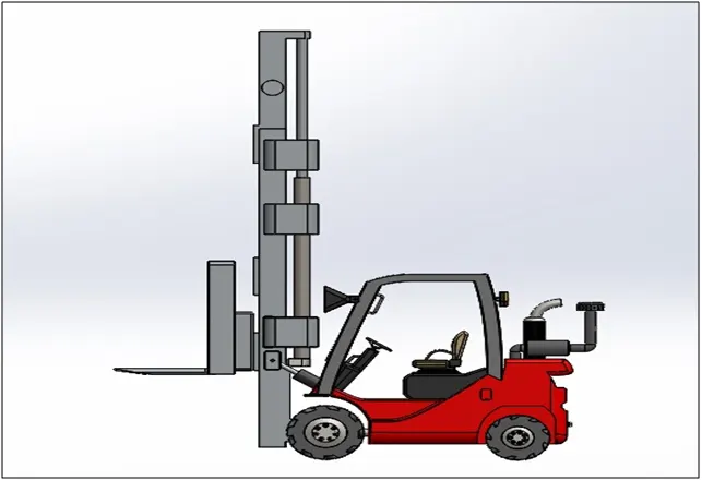
Fig 28. Assembly Side View
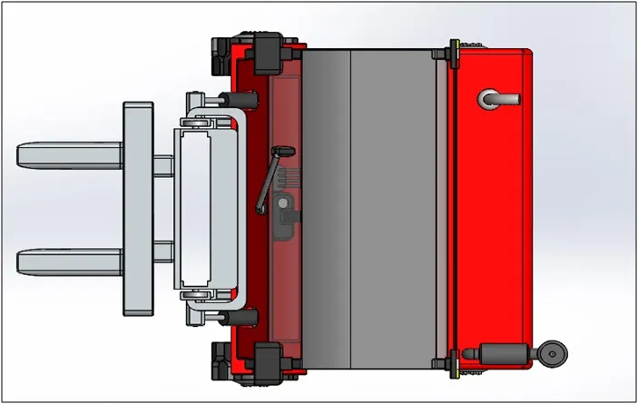
Fig 29. Assembly Top View
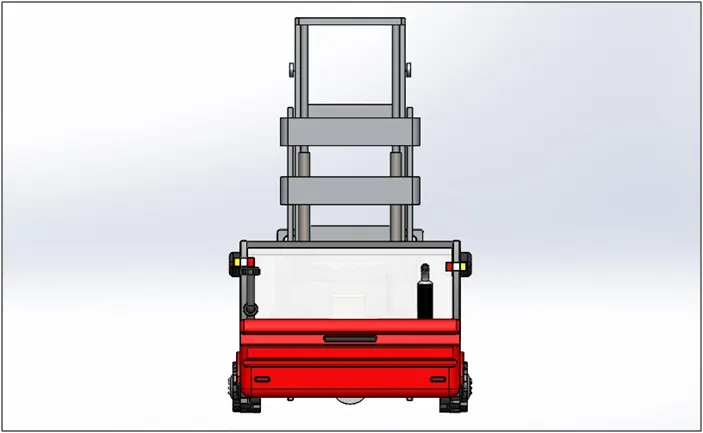
Fig 30. Assembly Back View
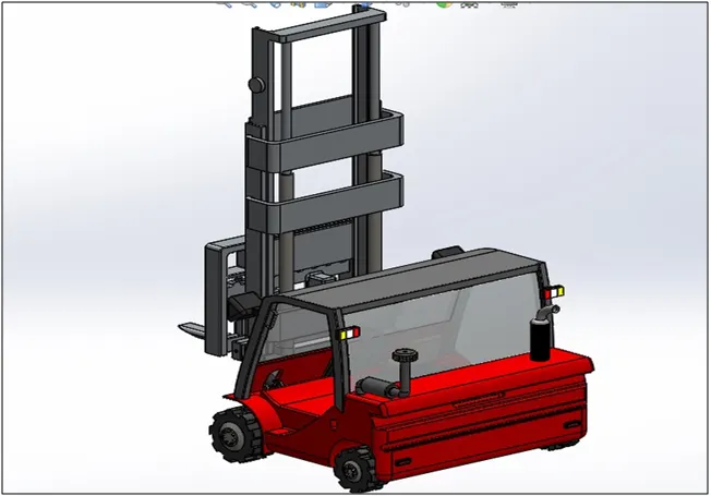
Fig 31. Assembly Isometric View
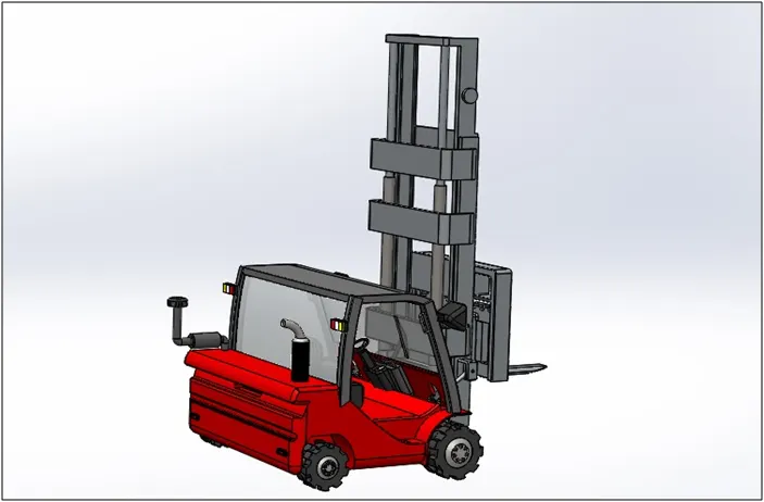
Fig 32. Assembly Camera Set Up view
RENDERING OF THE ASSEMBLY:
After the assembly of the forklift it is time to render the assembly to give it a nice finished look. The rendering can be done in solid works visualise or photo view 360.
- First of all select a suitable scene and a suitable environment for rendering the image.
- Make sure that that the image is nicely illuminated and clearly visible in the rendered image. If not different types of lights can be added, for e.g. directional light, spot light, sun light.
- Add decal graphics to the bike to give it a nice look.
- The Camera can be added to obtain the desired view for the render.
- After adding all these check it in the preview window and if satisfied go for the final render.
The forklift model has been rendered using Photo view 360.
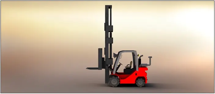
Fig 33. Assembly Render 1
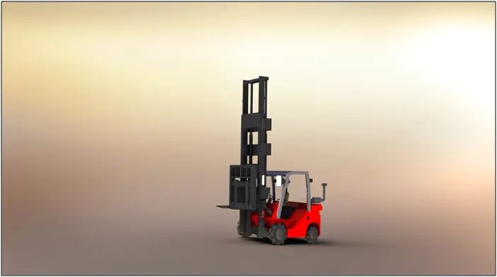
Fig 34. Assembly Render 2

Fig 35. Assembly Render 3
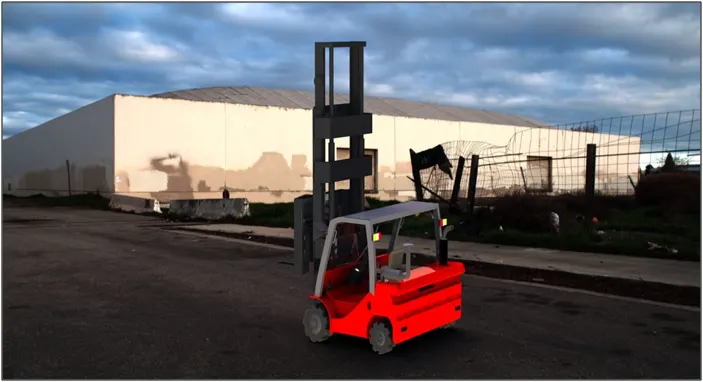
Fig 36. Assembly Render 4
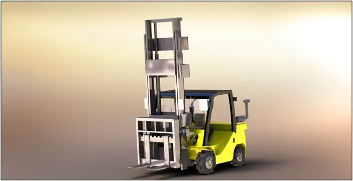
Fig 37. Assembly render 5
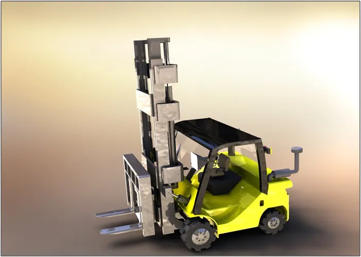
Fig 38. Assembly Render 6
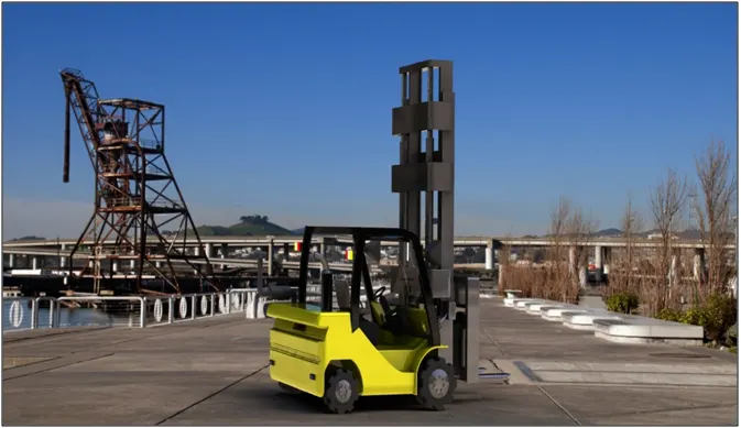
Fig 39. Assembly Render 7
CONCLUSION:
- The project gave me a good understanding of how to convert a 2D blueprint into a nice 3D model.
- The parts were designed and modelled in Solid works 2015. Got a good understanding of the solid modelling, surface modelling and about the different tools and features used in Solid works.
- The parts were assembled together to get the final product. Learnt the different ways to assemble the parts by applying different mates.
- The assembly was rendered using photoview 360.Learnt to apply the background scene, light and set up camera. Also learnt to add the decal graphics to the product.
********