Fender Design - Wheel Arch Challenge
FENDER DESIGN- WHEEL ARCH
AIM
To prepare a report explaining fender wheel arch regulations and check whether the given fender design meets the wheel arch European standards.
THEORY
FENDER:
Fender is the US English term for the part of an automobile, motorcycle, or other vehicle body that frames a wheel well (the fender underside). Its primary purpose is to prevent sand, mud, rocks, liquids, and other roads spray from being thrown into the air by the rotating tire. Fenders are typically rigid and can be damaged by contact with the road surface.
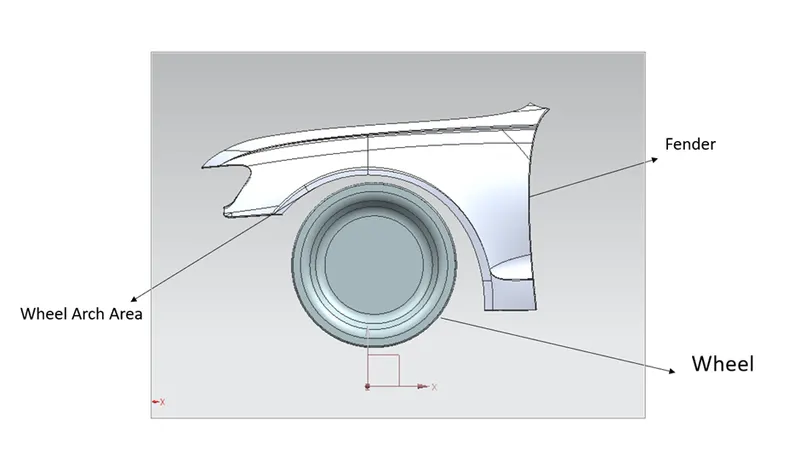
WHEEL ARCH:
The wheel arch is the semi-circular fender area above the wheel. There are different standards for different regions in order to design a good fender wheel arch area. The most common standards used for studying are Japan, European and U.S. standards. All these standard criteria are derived based on the conditions of the road in those regions.
Types of wheel arch regulation:
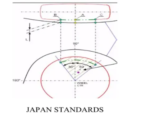
Japan standards
- Measure clearance L of a tire hub, cap & fender in three different positions within area K and produce clearance check chart to validate
- Clearance must be greater than 5 mm in all three positions.
- Wheel guard requirement: The value of 'a' shall be more than 5 mm at line 30 forward and 50 rearwards from the central vertical axis of the wheel.
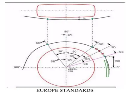
European standards
- Measure Clearance L at sections SA-SA SB-SB SC-SC SD-SD SE-SE and produce CL check chart to validate.
- At all five sections, the Clearance L value should be greater than 10 mm to satisfy. the European regulations.
- Wheel guard requirement: The value of 'a' shall be more than 5 mm at line 30" forward and 50 rearward from the central vertical axis of the wheel.
US. standards
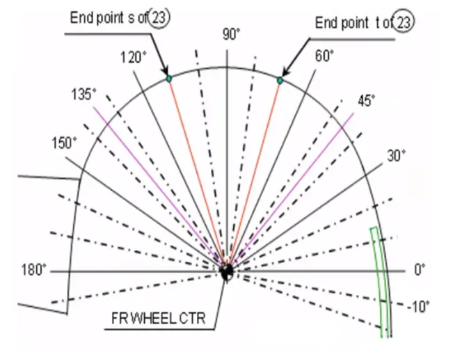
- Make clearance check details on all positions from -100* to 100* & make the clearance check table.
- All values should be greater than 5 mm to satisfy the regulations.
- The value of an a' shall be more than 5 mm at line 30* forward and 50* rearward from the central vertical axis of the wheel.
PROCEDURE
- Create a Datum plane on the outermost edge of the wheel.
- Create the axis like shown in the above image.
- The outer edge of the fender towards the wheel is projected into a sketch and the intersection points with all these four lines are made namely A, B, C, E. For point D the midpoint between points C and E along the projected edge is taken and a line is drawn from point D to wheel center.
- Project all the lines on the face edge and from all the intersection points to measure the clearance.
OBSERVATION
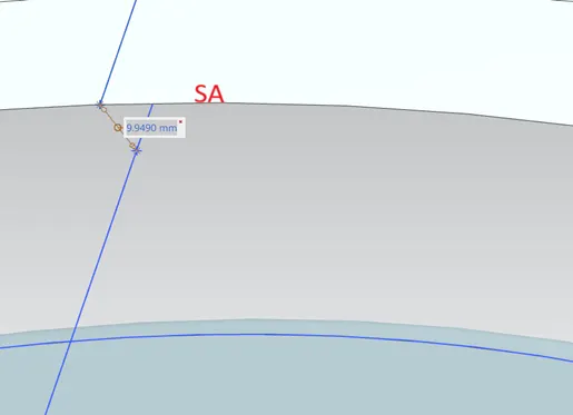
Clearance at SA is 9.9490mm.
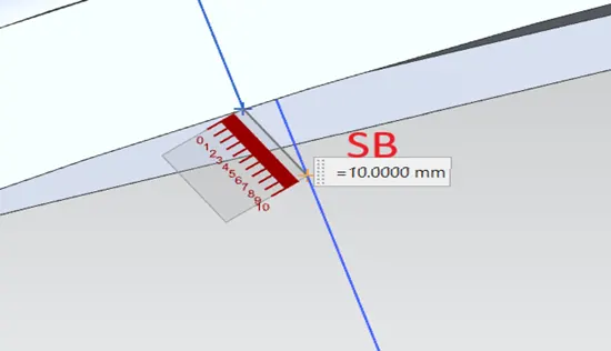
Clearance at SB is 10mm.
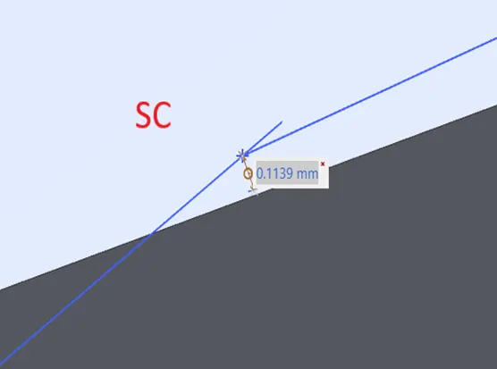
Clearance at SC is 0.1139mm.
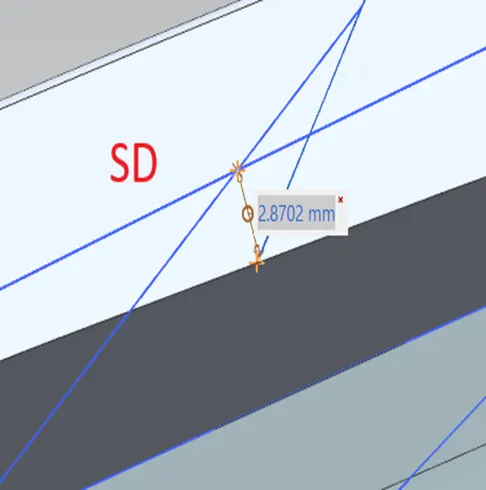
Clearance at SD is 2.8702mm.
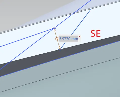
Clearance at SE is 5.9770mm.
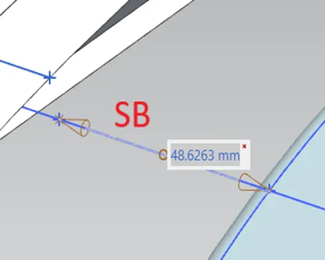
Wheel guard clearance at SB is 48.6263mm.
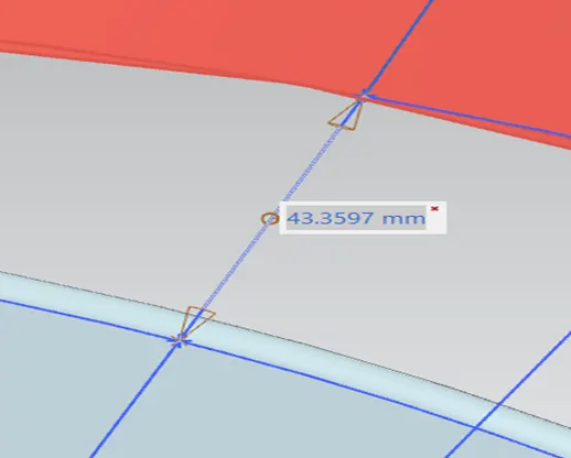
The wheel guard clearance at SC is 43.3597mm.
TABLE
CLEARANCE L:
|
SECTION |
MEASURED L |
CONDITION |
RESULT |
|
SA |
9.9490mm |
<10 mm |
FAIL |
|
SB |
10.0000mm |
=10 mm |
PASS |
|
SC |
-0.1139mm |
<10 mm |
FAIL |
|
SD |
-2.8702mm |
<10 mm |
FAIL |
|
SE |
-5.9770mm |
<10 mm |
FAIL |
WHEEL GUARD CLEARANCE a:
|
SECTION |
MEASURED a |
CONDITION |
RESULT |
|
SB |
48.6263mm |
>5 mm |
PASS |
|
SC |
43.3597mm |
>5 mm |
PASS |
CONCLUSION
From the above observation the clearance at SA, SC, SD, SE does not meet the European standards. Hence, the Frond fender wheel arch does not pass European standards.
The design team needs to re-design to meet the European standards.