Fender Design - Wheel Arch Challenge
AIM
To study different Fender design regulations and to determine whether the given design passes the European design standards.
Fender
It’s the part of the car body which forms the wheel well. The design of a car-fender requires to consider the size of the wheel, suspension length & travel, toe/camber angles and the space required for the turning wheels (turning radius), of the car. The main function of a fender is to prevent any type of road debris from being thrown onto the car’s components and body, onto traffic or onto pedestrians, by the rotating tires.
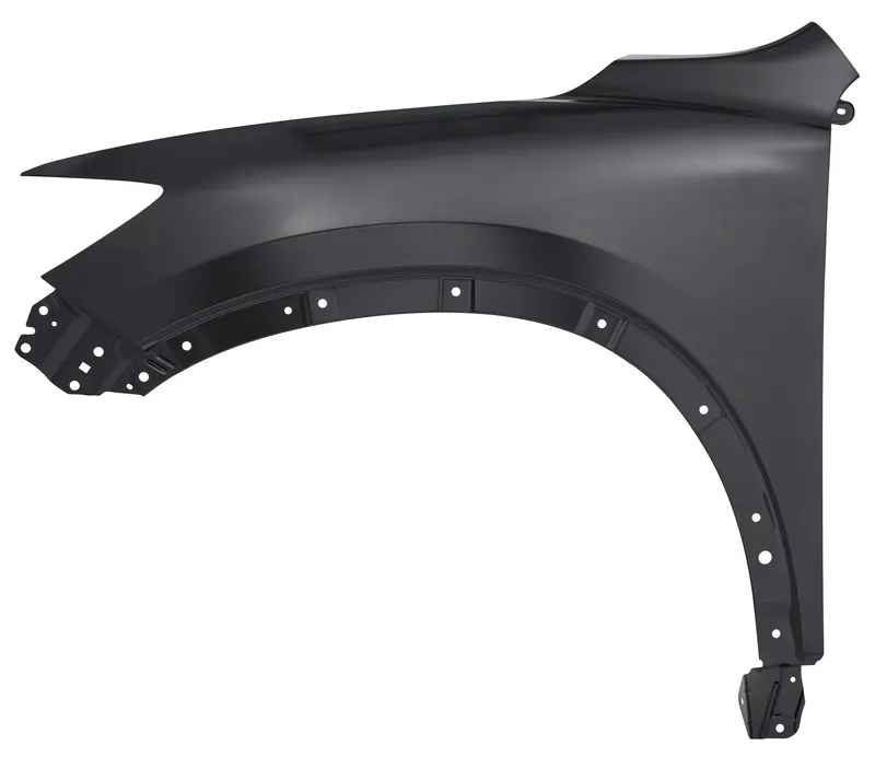
Wheel Arch
It’s the curved part attached to the fender above the wheel, joined to the baffle mounting region on the fender.
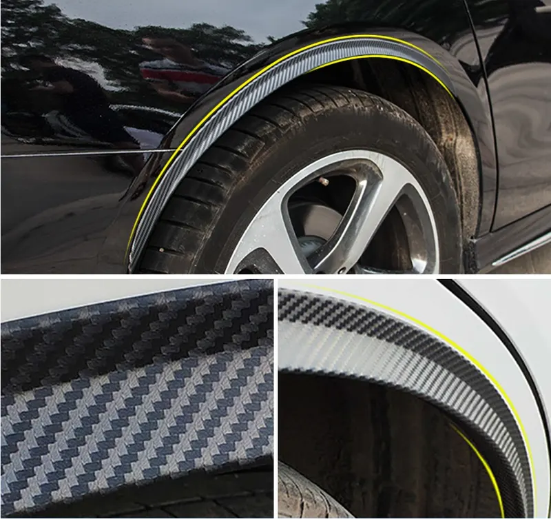
It’s design is different in different countries due to the different design regulations and standards followed, the clearance between the outer tip of side of the wheel and the inner edge of the wheel arch ( denoted by ‘L’ - as shown in the images below) -
- European Regulations
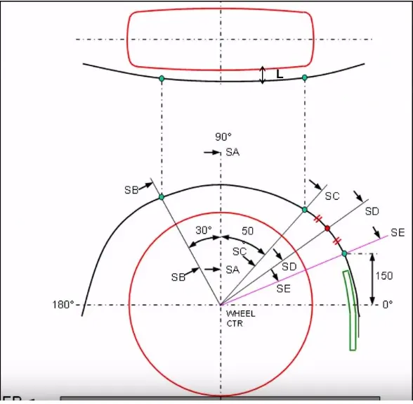
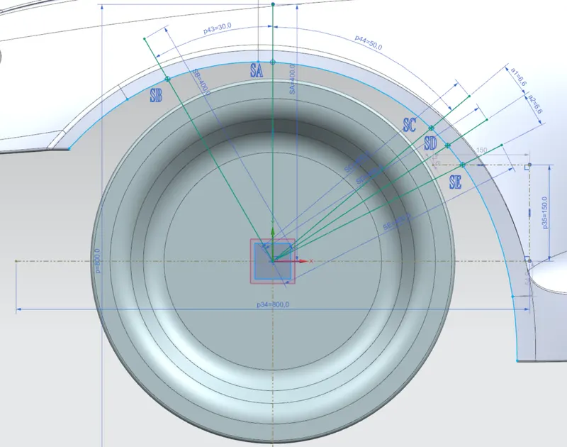
- The clearance ‘L’ is to be measured at the sections - SA, SB, SC, SD and SE.
- Section SA is the vertical passing through the center of the wheel.
- Section SB is the line 30°to the vertical, passing through the center of the wheel and in the forward direction.
- Section SC is the line 50°to the vertical, passing through the center of the wheel and in the rearward direction
- The horizontal line passing through the center is offset by 150mm in the upwards direction, the section SE is taken through the intersection of the wheel arch and the offsetted horizontal line.
- Section SD is taken in such a way that it divides the area in between sections SC and SD equally.
- All the five sections must have a clearance of minimum 10mm from the wheel arch.
- The values are tabulated and the design passes the regulations if all criteria is met.
- US regulations
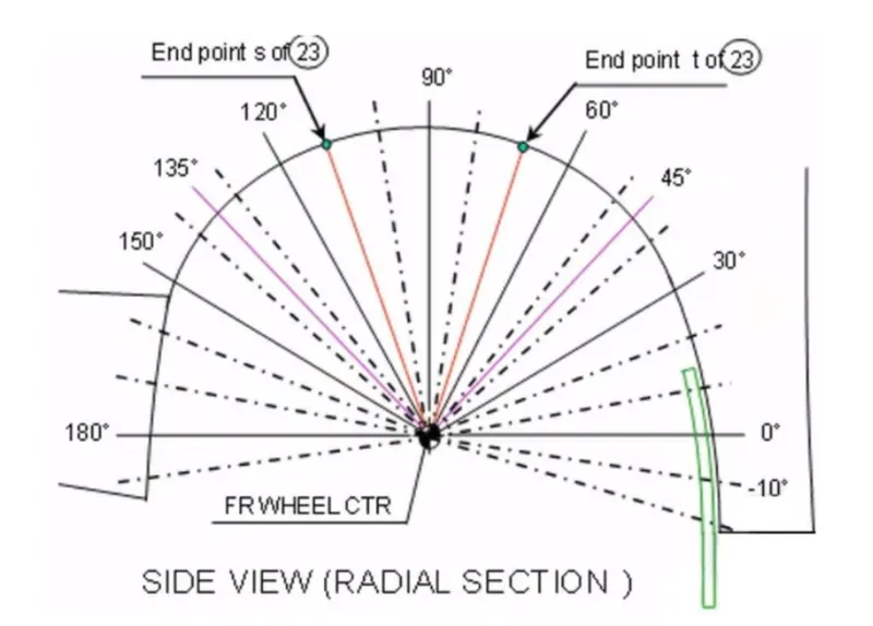
- The clearance ‘L’ is to be checked at all positions at regular intervals of 10°from the -20° position to the +200° position (i.e, 100° to the forward and rearward directions from the vertical passing through the center of the wheel) .
- All the clearance values must be at a minimum of 5mm at all sections.
- The values are tabulated and the design passes the regulations if all criteria is met.
- Japanese Regulations
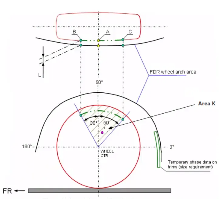
- The clearance value ‘L’ is measured within the area K, as shown in the image above, at positions A, B and C.
- Point A is onthe intersection of the vertical passing through the center of the wheel and the wheel arch
- Point B is selected on the line 30° in the forward direction to the vertical passing through the center of the wheel.
- Point C is selected on the line 50° in the rearward direction to the vertical passing through the center of the wheel.
- The values are tabulated and the design passes the regulations if all criteria is met.
Analysis of the given Fender Design using the European Standards of regulations.
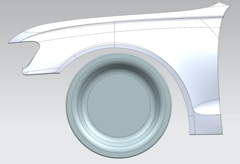
- A sketch marking all the required sections is to be created, in relation to the given design.
- A datum plane is created on the outermost face of the wheel, with the center of the wheel as the center of the plane.
- The circular edge of the outer layer of the wheel is taken for reference to calculate the clearance.
- The references of the vertical & horizontal passing through the center of the wheel is drawn.
- The horizontal reference offset by 150mm in the upwards direction is taken.
- The curve of the wheel arch is projected to the sketch plane.
- Sections SA, SB, SC,SD and SE are to be taken according to the European regulations (explained above).
- Points of reference for each section is marked on the projected wheel arch curve.
- Textfunction is used to name the relevant sections for identification.
- Rapid Dimensiontool is used to constrain the sketch.
- The reference points are projected on to the wheel arch edge for calculating the distance between the wheel-arch points and the points on the sketch plane.
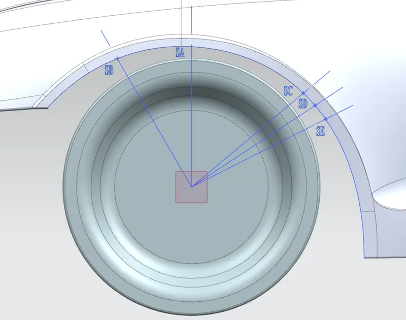
- All the clearances are measured using the Measure Distance
Reuslts -
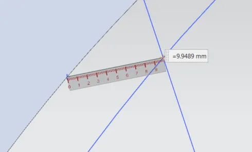
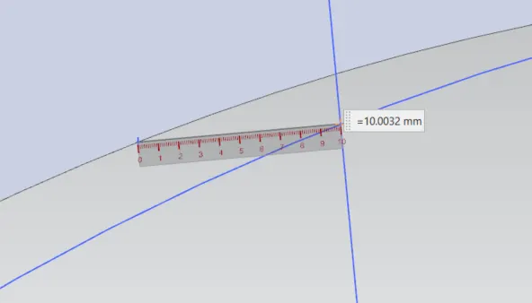
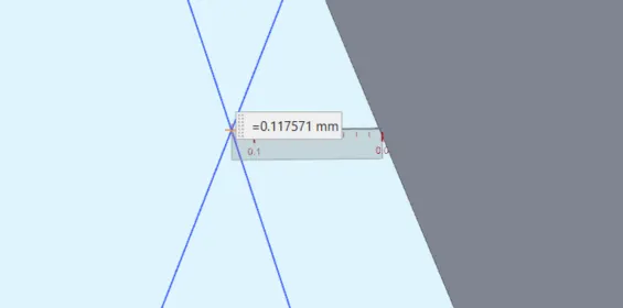
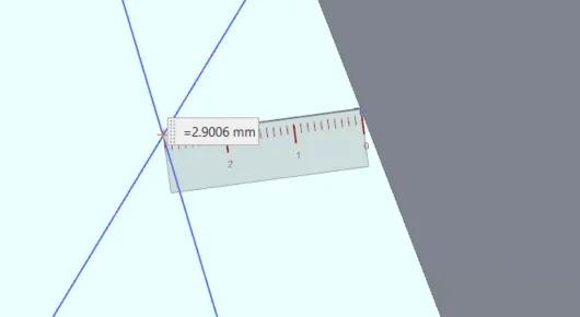
The clearance values at the sections are -
- SA
- SB
- SC
- SD
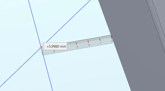
- SE
|
SECTION |
CLEARANCE, L ( ˃ 10mm) |
RESULT |
|
SA |
9.9489mm |
FAIL |
|
SB |
10.0032mm |
PASS |
|
SC |
- 0.11757mm |
FAIL |
|
SD |
- 2.9006mm |
FAIL |
|
SE |
- 5.9980mm |
FAIL |
- The ‘-ve’ implies that the wheel edge has gone outside the wheel arch.
Conclusion
The provided Fender design has values of clearances which don’t meet the requirements the European Standards. Thus, this Design Fails to pass the regulations.