Fender Design - Wheel Arch Challenge
WHEEL ARC CHALLENGE :
A) AIM :
Main objective of the project is to calculate the Wheel arch area, and also conclude, If the car will pass the European standards or not.
B) FENDER WHEEL ARCH :
1) Wheel Arch is the semi-circular part of the fender positioned above the wheel of the vehicle.
2) The design of the wheel arch of the fender should be such that it must shield wheels and protect both passengers compartment and pedestarians from the projection of water, mud and stones.
3) The wheel arch area of the fender is usually designed as a cover or shield over the tyre along its perimeter to stop any debris or stones ,dirt,sand,snow,etc,from getting thrown into the vehicle or the BIW area as well as outside the vehicle and onto other vehicles or pedestarians on the road.
4) For the vehicle to has its permit in different countries,the wheel arch of fenders must be compliant with the standards and regulations set by respective countries.
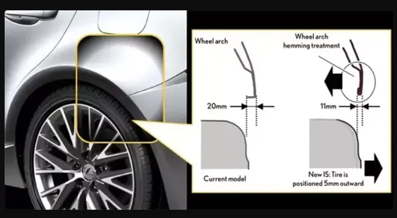
FIG : WHEEL ARC
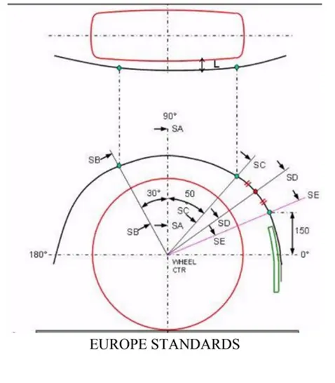
C) EUROPEAN REGULATIONS :
The value will be more than 10mm at 30 degree at forward and 50 degree at line above 150 mm
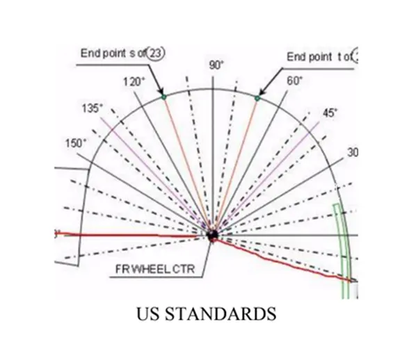
D) US REGULATIONS :
The value will be more than 5mm at line 30 degree forward and 50 degree central vertical axis.
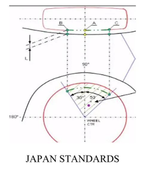
E) JAPANESE REGULATIONS :
The value will be more than 5mm at 30 degree at forward and 50 degree at the central vertical line.
F) Calculation of wheel arch area according to European Regulations :
The procedure to calculate distance between wheel arc and wheel is given below,
1) A Datum Plane is created at the outermost face of the wheel
2) The sketch is created on the new Datum Plane
3) A Horizontal line is drawn across the centre of the wheel
4) A perpendicular line SA is dropped at the centre of the wheel
5) Two lines SB and SC are created at 30° forward of SA and 50° rearward of SA respectively
6) A point is created 150mm vertically above the centre line
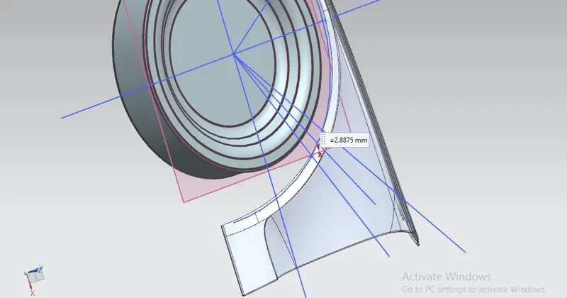
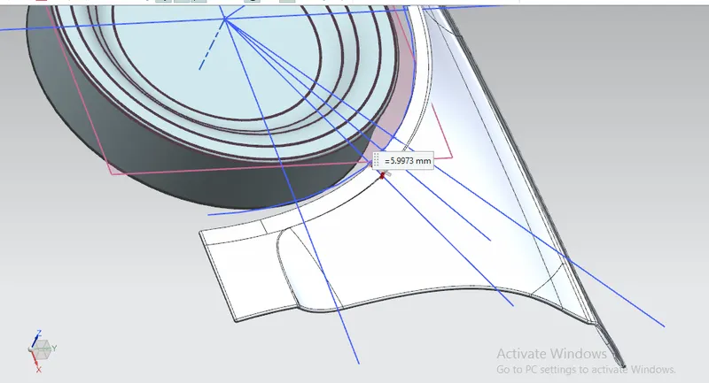
7) A line SE is drawn from the wheel centre and passes from the point created
8) Another line SD is drawn from the centre of the wheel and in the middle of lines SC and SE
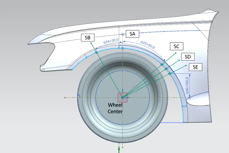
FIG : WHEEL ARC SKETCH
G) Calculation of the clearence value"L" as following:-
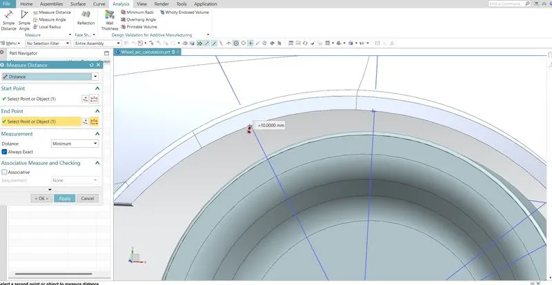
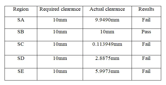
1] The Measuring 'L' for the given wheel and fender at SB- The value of 'L' at SB= 10.0000 mm.
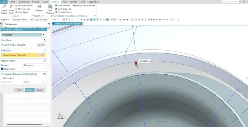
2] The Measuring 'L' for the given wheel and fender at SA- The value of 'L' at SA= 9.9490 mm.
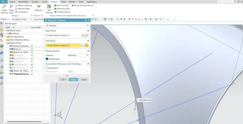
3] The Measuring 'L' for the given wheel and fender at SC- The value of 'L' at SC= 0.113949 mm.
4] The Measuring 'L' for the given wheel and fender at SD- The value of 'L' at SD= 2.8875 mm.
5] The Measuring 'L' for the given wheel and fender at SE- The value of 'L' at SE= 5.9973 mm.
H) RESULTS :
I) CONCLUSION :
1) The value of Clearance (L) is measured at all five location and tabulated.
2) The table shows that only a section SB have 10 mm clearance and at remaining four section value will not have more than 10mm
3) From the above results we can conclude that the fender does not pass the European regulations, as the minimum clearance L between the fender wheel arch and wheel for vehicle and pedestrian safety is 10mm and this design does not meet the requirement.