Fender Design - Wheel Arch Challenge
Fender:
Fender is a part of an automobile, motorcycle or other vehicle body that frames a wheel well (the fender underside). Its primary purpose is to prevent sand, mud, rocks, liquids, and other road spray from being thrown into the air by the rotating tire. Fenders are typically rigid and can be damaged by contact with the road surface.
The main purpose of fenders on cars is that they shield the wheels and they protect the passengers, the pedestrians, and the other vehicles from stones, mud, liquid, and other debris that can fly in the air because of the speeding rotating wheels while the car is running.
Wheel Arch:
- It is a curved part of the Fender positioned right above the Wheel.
- The Wheel Arch is designed such that it protects both the pedestrian and car cabin from mud, water rocks and other road spray
- Different countries have different wheel arch regulations in place, and the wheel arch design has to comply with them to be deemed usable in that country.
- For avoiding design alterations of the same vehicle to meet the different regulations in different countries, the maximum values of the concerned regulation parameters are taken into consideration for design purpose.
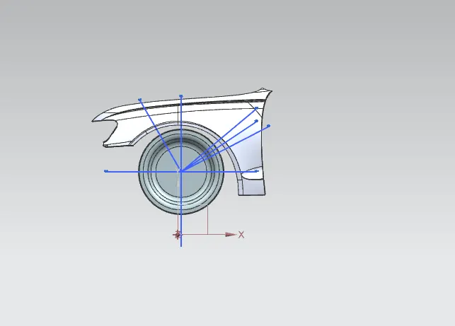
Fender Wheel Arch Regulations:
Japan Regulations:
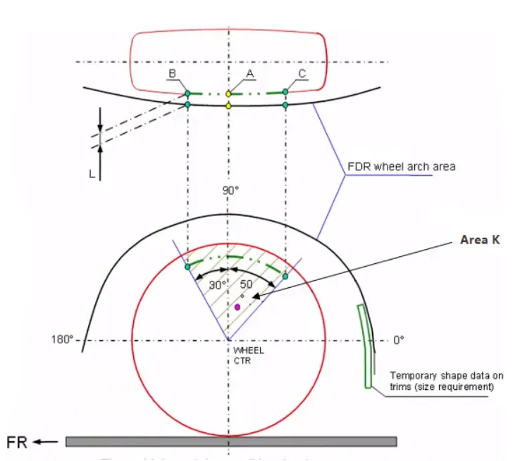
- The clearance ‘L’ for tire, hub, cap and fender is to be measured within area K and create clearance check chart to validate
- The value of L should be greater than 5mm at all positions
- Wheel guard requirement: The value of ‘a’ should be more than 5mm at line 30° forward and 50° rearwards from the central vertical axis of the wheel
European Regulations:
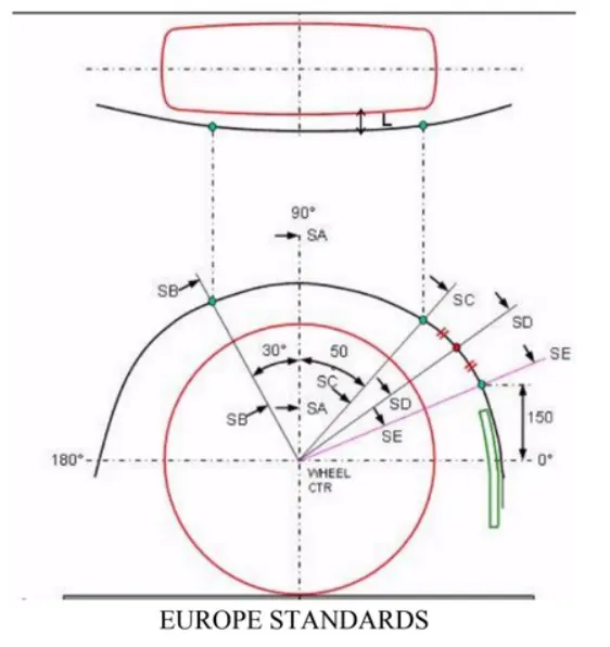
- The Clearance ‘L’ should be measured at sections SA-SA, SB-SB, SC-SC, SD-SD and SE-SE and create clearance check chart to validate
- At all the five sections the value of L should be greater than 10mm to satisfy the European Regulations
- Wheel guard requirement: The value of ‘a’ should be more than 5mm at line 30° forward and 50° rearwards from the central vertical axis of the wheel
US Regulations:
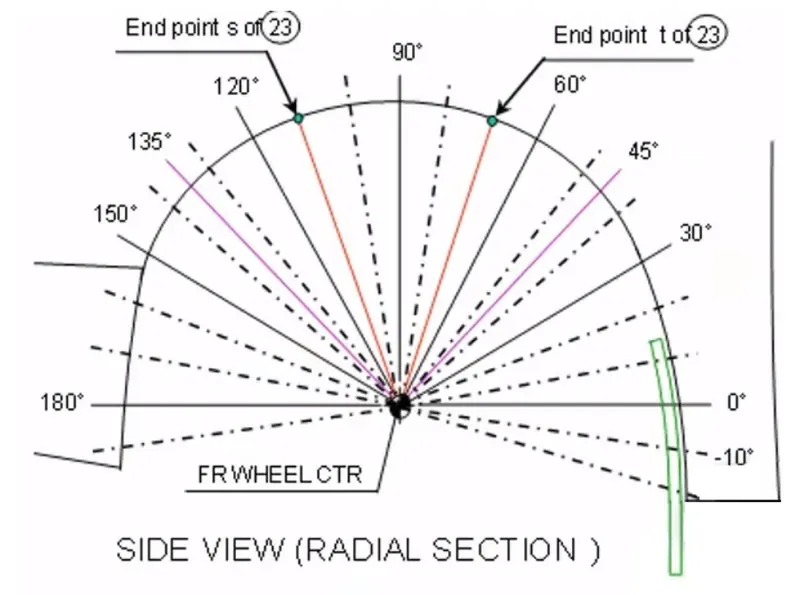
- Clearance ‘L’ is to be checked at all positions from -100° to 100° and create clearance check chart to validate
- The value of L should be greater than 5mm to satisfy the regulations
- Wheel guard requirement: The value of ‘a’ should be more than 5mm at line 30° forward and 50° rearwards from the central vertical axis of the wheel
Obtaining the clearance L at the designated 5 points:
The clearance distance 'L' is calculated at points SA-SA, SB-SB, SC-SC, SD-SD and SE-SE, which should be greater than or equal to 10mm
i.) Clearance 'L' at SA-SA:
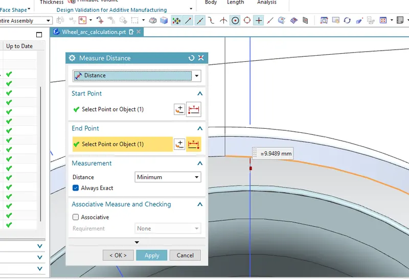
L = 9.9489mm
ii.) Clearance 'L' at SB-SB:
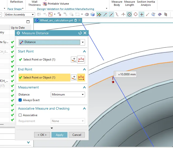
L= 10mm.
iii.) Clearance 'L' at SC-SC:
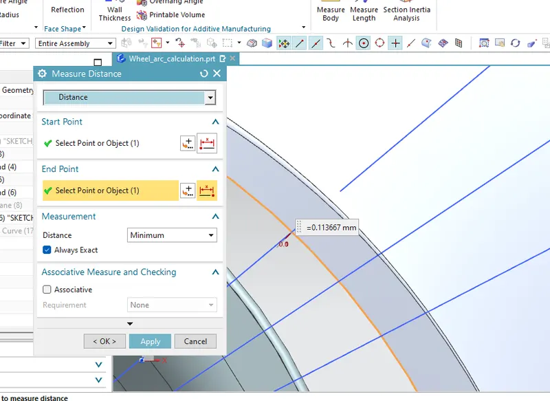
L= 0.113667.
iv.) Clearance 'L' at SD-SD:
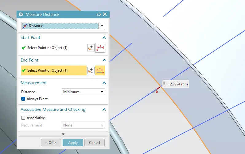
L= 2.7724.
v.) Clearance 'L' at SE-SE:
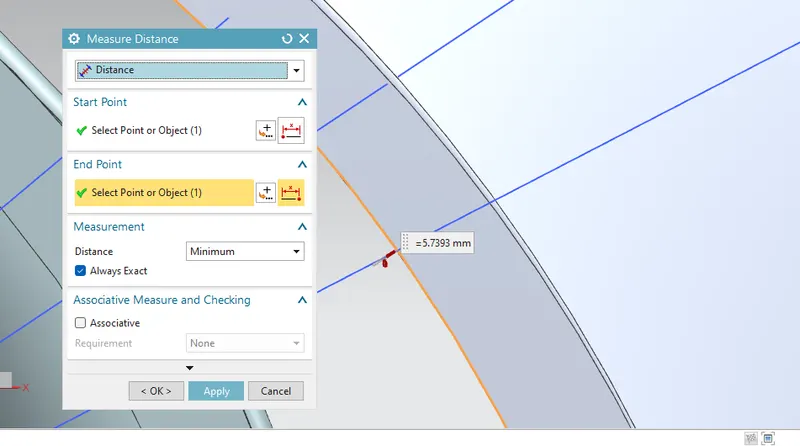
L= 5.7393.
TABULATION:
| SECTION | REQUIRED DISTANCE | CALCULATED DISTANCE | RESULT |
| SA | 10 mm | 9.9489 mm | FAIL |
| SB | 10 mm | 10.00 mm | PASS |
| SC | 10 mm | 0.113667 mm | FAIL |
| SD | 10 mm | 2.7724 mm | FAIL |
| SE | 10 mm | 5.7393 mm | FAIL |
CONCLUSION:
Acooding to European requirement the wheel arch is not good for manufacturing ,so styling team do design team should work on section SA,SC,SD and SE.