Fender Design - Wheel Arch Challenge
Objective
To calculate the wheel arc for given Fender model, by means of the European standards regulations.
Requirements for wheel guards
- GENERAL REQUIREMENTS
1.1. The motor vehicle shall be provided with a wheel guard for each wheel.
1.2. The wheel guard may consist of parts of the bodywork or separate mudguards and shall be so designed as to
protect road users, as far as possible, against thrown-up stones, mud, ice, snow and water and to reduce the
dangers due to contact with rotating wheels.
- SPECIFIC REQUIREMENTS
2.1. The wheel guards shall meet the following requirements with the vehicle's mass adjusted to that of the
manufacturer's declared mass in running order with one additional passenger on the first seating row and the
steered wheels in the straight ahead position.
2.1.1. In the part formed by radial planes at an angle of 30° towards the front and 50° towards the rear of the centre of
the wheels (see Figure 1), the overall width (q) of the wheel guard shall be at least sufficient to cover the total
tyre width (b) taking into account the tyre envelope as well as the extremes of the tyre/wheel combination(s) as
specified by the manufacturer. In the case of twin wheels, the tyre envelopes and total width over the two tyres
(t) shall be taken into account.
2.1.1.1. For the purposes of determining the widths referred to in paragraph 2.1.1, the labelling (marking) and
decorations, protective bands or ribs on tyre walls are not taken into account.
2.1.2. The rear of the wheel guard shall not terminate above a horizontal plane 150 mm above the axis of rotation of
the wheels, furthermore:
2.1.2.1. In case of single wheels, the intersection of the rear edge of the wheel guard with the horizontal plane as defined
in paragraph 2.1.2 (see Figure 1, point A) shall lie outwards of the median longitudinal plane of the tyre.
2.1.2.2. In the case of twin wheels, the intersection of the rear edge of the wheel guard with the horizontal plane as
defined in paragraph 2.1.2 (see Figure 1, point A) at the outside wheel shall lie outwards of the median
longitudinal plane of the outermost tyre.
2.1.3. The contour and location of each wheel guard shall be such that they are as close to the tyres as possible. In
particular within the part formed by the radial planes referred to in paragraph 2.1.1, the following requirements
shall be satisfied:
2.1.3.1. The depth (p) of the recess situated in the vertical plane of the tyre axis, measured from the outward and inward
edges of the wheel guard at the vertical longitudinal plane passing through the centre of the tyre inside the wheel
guard, shall be at least 30 mm. This depth (p) may be reduced progressively to zero towards the radial planes
specified in paragraph 2.1.1.
2.1.3.2. The distance (c) between the lower edges of the wheel guard and the axis passing through the centre of rotation
of the wheels shall not exceed 2 × r, where the radius (r) is the static radius of the tyre.
2.1.4. In the case of vehicles having an adjustable suspension height, the abovementioned requirements shall be met
when the vehicle is in the normal running position as specified by the vehicle manufacturer.
2.2. The wheel guards may consist of several components, provided that no gaps exist between or within the
individual parts when assembled.
2.3. The wheel guards shall be firmly attached. However, they may be detachable either as a unit or in parts.
- USE OF SNOW TRACTION DEVICES
3.1. In the case of vehicles where only two wheels are driven, the manufacturer shall certify that the vehicle is so
designed that at least one type of snow traction device can be used on at least one of the tyre and wheel
combinations approved for the driven axle of the vehicle. The snow traction device and tyre/wheel
combination(s) suitable for the vehicle type shall be specified by the manufacturer under item 6.6.4 in the
information document.
L 292/28 Official Journal of the European Union 10.11.2010 EN
3.2. In the case of vehicles where all wheels are driven, including vehicles where drive axles can be disengaged either
manually or automatically, the manufacturer shall certify that the vehicle is so designed that at least one type of
snow traction device can be used on at least one of the tyre and wheel combinations approved for the driven
axle, which cannot be disengaged, of the vehicle. The snow traction device and tyre/wheel combination(s)
suitable for the vehicle ty pe shall be specified by the manufacturer under item 6.6.4 in the information
document.
3.3. The vehicle manufacturer shall include relevant instructions regarding the correct use of the specified snow
traction devices in the vehicle handbook and this information shall be given in the national language, or at least
one of the national languages, of the country in which the vehicle is offered for sale.
Figure 1
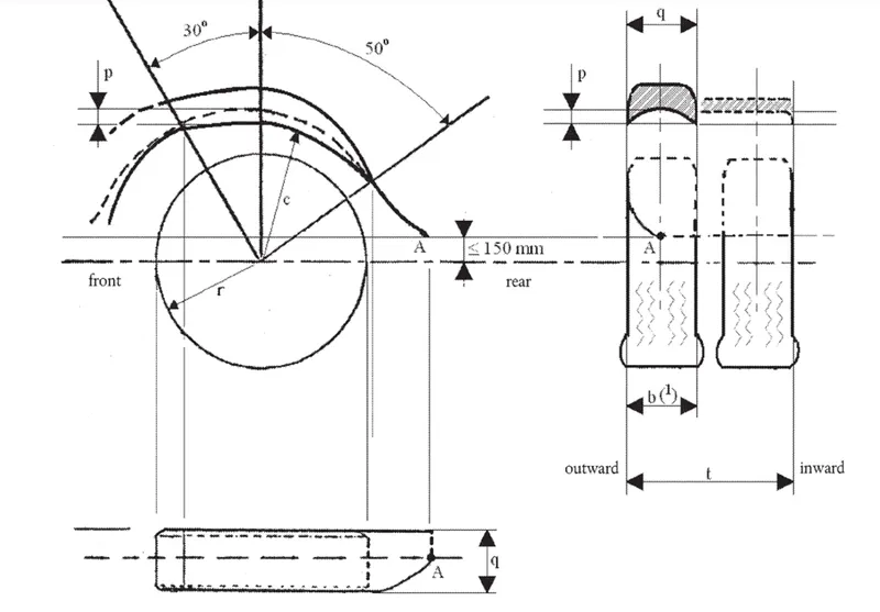
Diagram of wheel guard
1) The tyre width (b) is determined at the top part of the tyre (tyre section width between the radial planes as referred to
in paragraph 2.1.1)
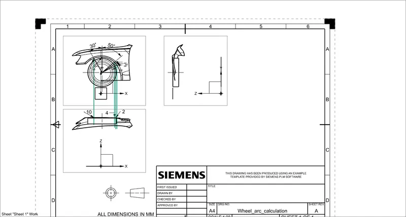
- In above fig. sa and sb satisfy the min. 10mm distance requirement.
- sc is 4mm which does not satisfy the requirement.
- sd is 2mm which does not satisfy the requirement.
Conclusion:-
Hence we can declare that the following fender wouldn’t pass the standards the styling team must redesign the fender.