Fender Design - Wheel Arch Challenge
FENDER DESIGN - WHEEL ARCH CALCULATION:
Wheel Arch is the semi-circular part of the fender positioned above the wheel of the vehicle. The design of the wheel arch of the fender should be such that it must shield wheels and protect both passengers compartment and pedestarians from the projection of watr, mud and stones.The wheel arch area of the fender is usually designed as a cover or shield over the tyre along its perimeter to stop any debris or stones ,dirt,sand,snow,etc,from getting thrown into the vehicle or the BIW area as well as outside the vehicle and onto other vehicles or pedestarians on the road.For the vehicle to has its permit in different countries,the wheel arch of fenders must be compliant with the standards and regulations set by respective countries.
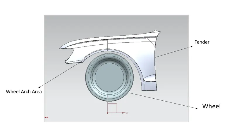
- TYPES OF WHEEL ARCH REGULATIONS:
- JAPAN REGULATIONS:
It says we need to draw two lines with wheel's center point and reference to the vertical line on the wheel with 30o on the left and 50o on the right. Projecting the points to the wheel arch the points must be 5mm or above.
- EUROPEAN REGULATIONS: In Japan, it also says to draw two lines with a wheel center point and reference to a vertical line on the wheel with 30o on the left and 50o on the right. Projecting the points to the wheel arch the points must be 10mm or above. And additionally, we will have to take a 150mm point from the zero or horizontal line of the wheel and also in between the 150mm point and the 50o point we will also take a midpoint. Along with this, we need to measure “a” the distance between the outermost layer and the SB, SC should be above 5mm.
- JAPAN REGULATIONS:
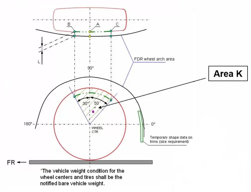
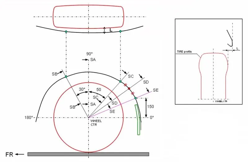
- US REGULATIONS: Here in USA we need to take points for every 10o from -20o of the right side to 0 of the wheel and all must be 5mm or above.
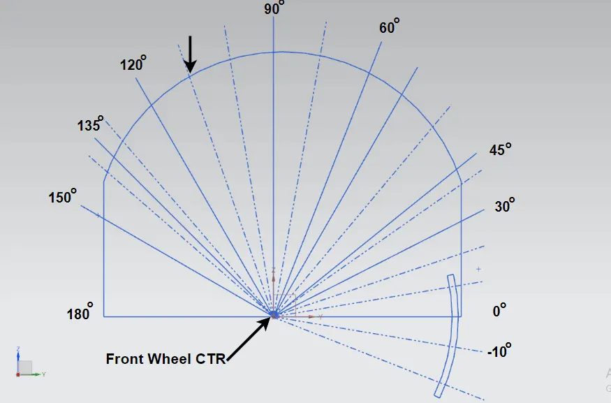
- ANALYSIS:
- There are different regulations in this regard based on different regions. This analysis has been done according to European Regulations.
- The part file was opened using NX CAD and the points were plotted on the wheel arch after taking the required measurements from the wheel centre.
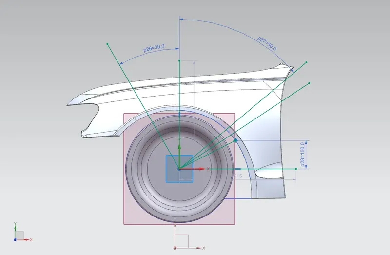
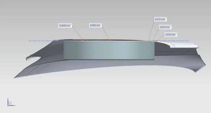
The clearance value 'L' was measured and found to be as follows:
|
Section |
Required Clearance (mm) |
Measured Clearance ‘L’ (mm) |
Remarks |
|
SB |
10 |
10 |
Pass |
|
SA |
10 |
9.9490 |
Fail |
|
SC |
10 |
0.113949 |
Fail |
|
SD |
10 |
2.8875 |
Fail |
|
SE |
10 |
5.9973 |
Fail |
From the above observations, the positions SA SC SD SE are less than 10mm. It will fail in European Regulations.
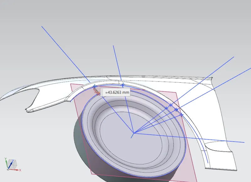
Calculating the 'a'
'a' is the distance between Fender and the wheel's outermost edge.
It should be more than 5 mm

a1= 43.6263 mm
a2 = 38.3597 mm
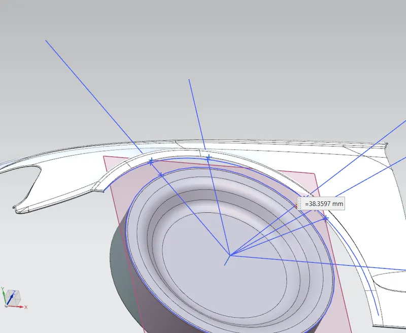
so both areas clear the 'a'