Fender Design - Wheel Arch Challenge
Fender wheel arch challenge
Fenders are curve shaped housing that houses the wheel and its supporting components. It is designed to allow the wheel to rotate and steer the wheels without its interference. Fenders are aesthetic as well as safety components therefore various factors like surface finish, projections, looks, as well as must satisfy with the safety regulations.
The fender has been a component in automobile design from the very beginning. Fenders are much more distinctive in cars from the model-T days up to the oversized sedans of the 1950s.in olden cars the fenders caused a distinctive look which projected out from the door panels. Modern cars also have fenders but not projecting out. The fender fends off the damaging debris from the road and also plays a major role in avoiding the debris from hitting the pedestrians.
Fenders have many types, ordinary commercial cars having curved metal guards that do not follow the contour of the wheel, while luxury and high performing racing models have fenders that trace along the wheel with little gap in between.
Most fenders are made of steel or the same material as the body. Its purpose is to protect the body from particles that are evaded by the surface. It protects vehicles from stones, mud, dirt, and water that may damage the panel.
Fender designs must follow the regulations which are passed in order to ensure safety. There are 3 regulatory norms that apply norms for fender design. European, Japanese, United States standards. All have their own regulation as per their own road conditions. We consider European standards to check for whether the given design satisfies the norms.
The given image consists of 5 points SA, SB, SC, SD and SE respectively. At these points the clearance between the fender and the tyre outer surface should be atleast 10 mm. If the condition is not satisfied the fender design must be altered to satisfy the same.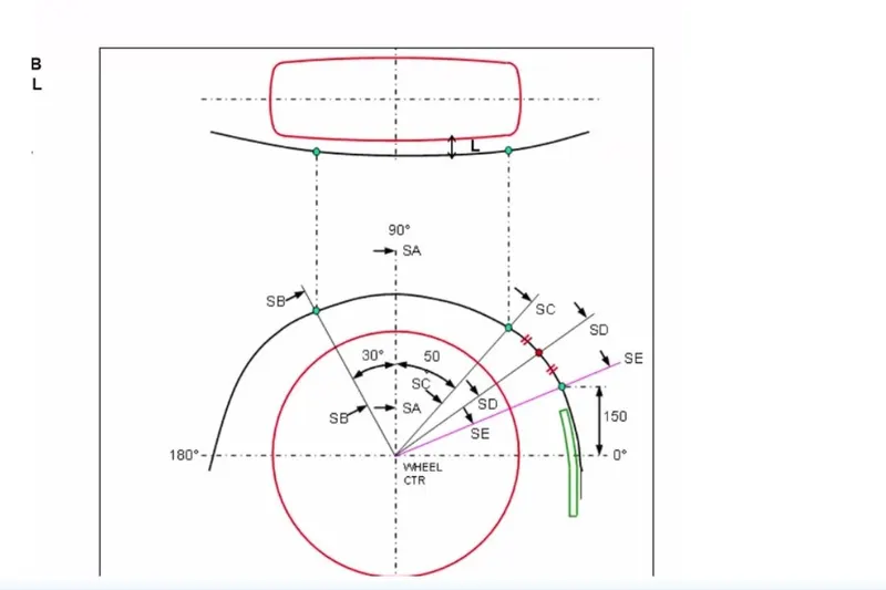
We now check the given design that if it satisfies the European standards at the given points
At SB we 1st check if the condition is satisfied
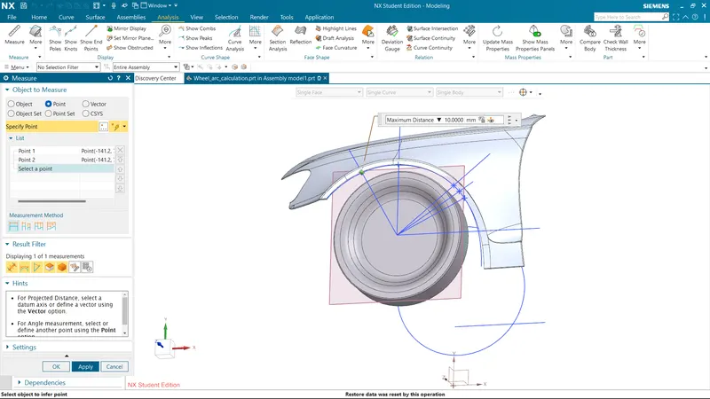
SB= 10 mm.
Similarly we check for all the remaining sections,
At SA
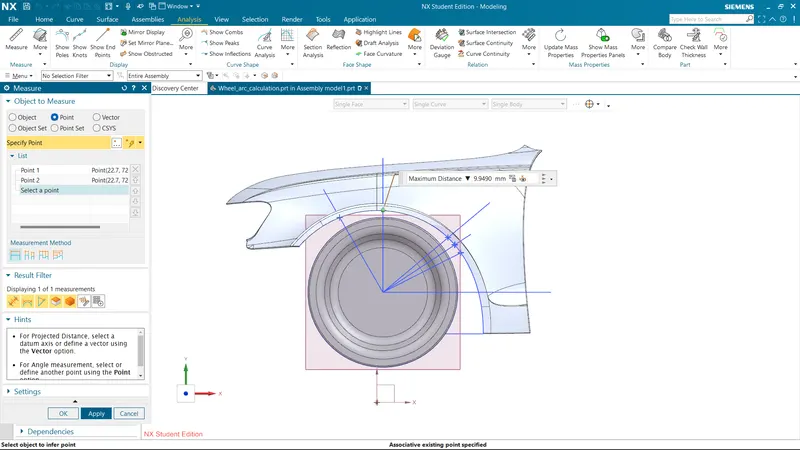
SA= 9.949 mm.
At SC
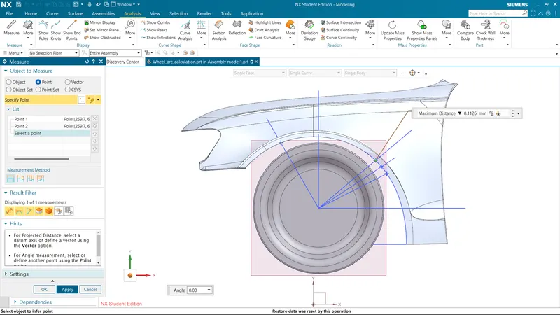
SC= -0.1126 mm.
At SD
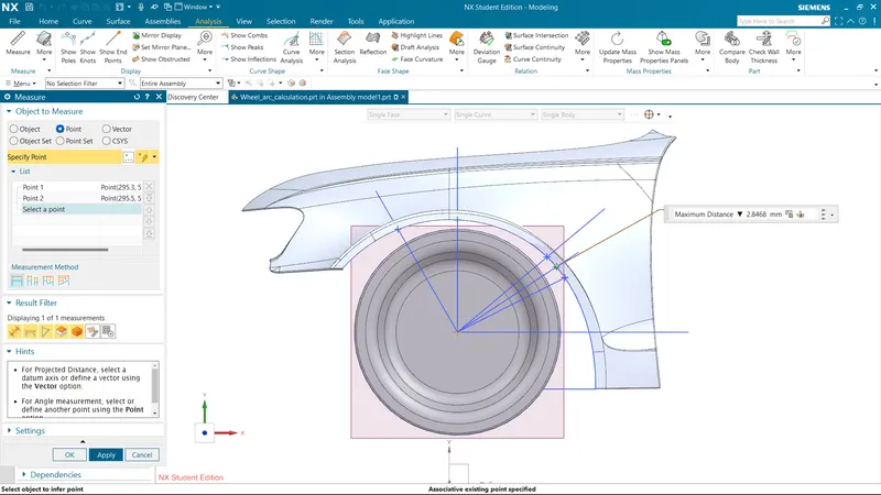
SD=-2.8468 mm.
At SE
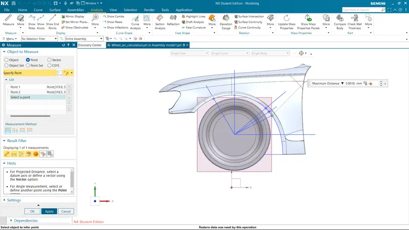
SE = -5.9018 mm.
Also, we measure the clearence b/w the wheel and the fender which must be greater than 5mm at SB & SC points.
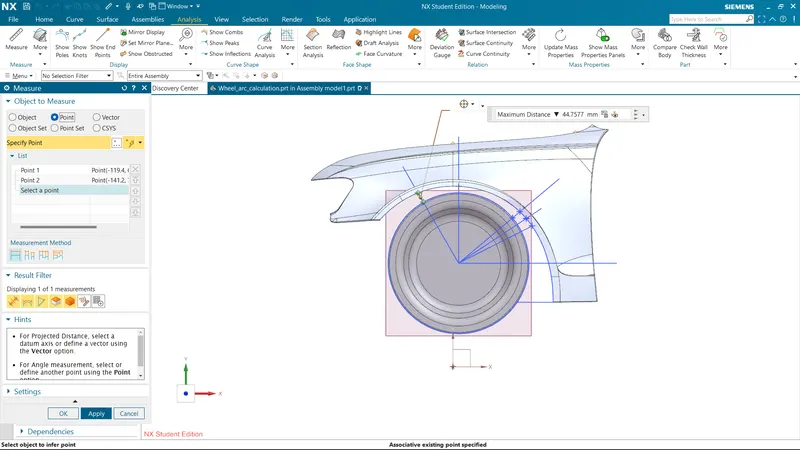
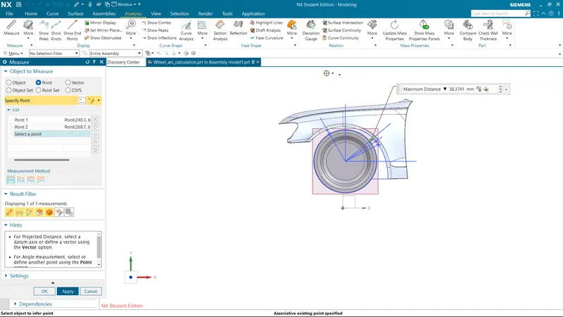
From the above references we realise that execpt for SB section all the other sections SA,SC,SD,SE doesn't satisfy the regulation we conclud that the design is not safe and must be reworked to satisfy the same.