Fender Design Challenge
DESIGN OF FRONT FENDER-
OBJECTIVE- To develop the front fender using Nx cad following the design parameters .
INTRODUCTION -
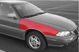
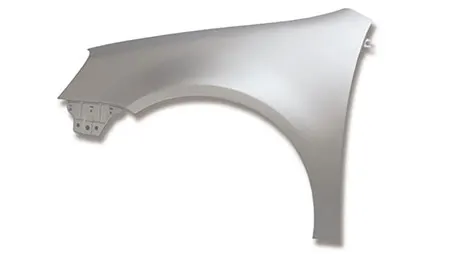
Front fender is a part of the vehicle that frames the wheel . the primary purpose of the fender is to prevent sand , mud , rock etc from being thrown away into the air by rotating tire . fender can be of two types , full bumper type and half bumper type . nowadays half bumper type fender is typically used . the cost of sheet metal blank is reduced as we can produce two half bumper type fender in single blank . this also leads to reduction of scrap .
DESIGN PARAMETERS -
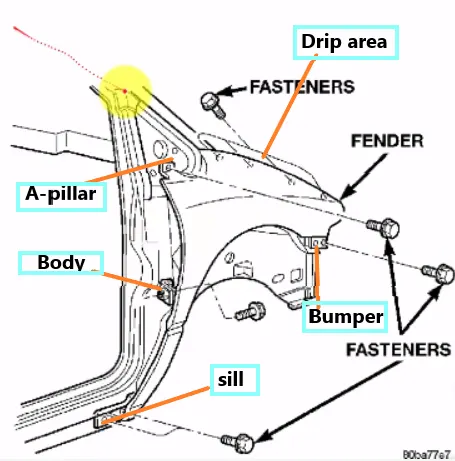
The front fender is manufactured as a separate part , this is then mounted to the body of car , for this the front fender basically has 5 mounting points, but this mounting points can differ from OEm to another OEM .below is the points -
Drip area:
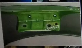
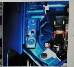
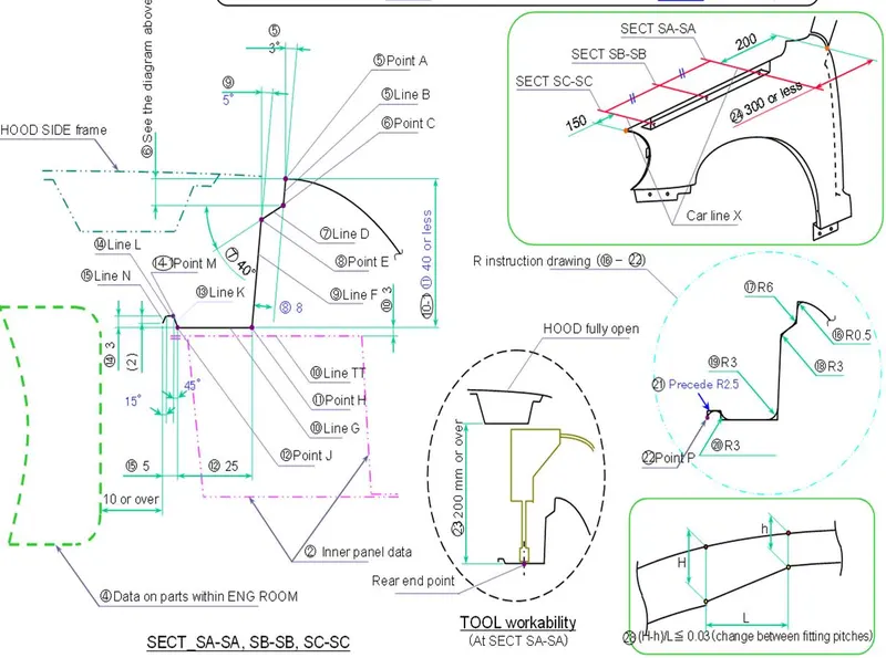
Drip area mounting is the important part in the fender . this mounting is attached to the engine compartment of the car . fender drip area is mounted via weldnuts to the engine compartment .a min of 150mm distance is kept from the front side and a distance 300mm or less can be kept on the rear side . the total length of drip area from the top of fender should be less than 40mm , this is to avoid the springback during the manufacturing . the edge of the mounting should atleast 10mm away from any nearby component in the engine . a rigidity bead is provided at the end to increase the strength of the mounting .
A-pillar area -
The A-pillar area mounting depends upon the A-pillar of the car . the mounting can also be provided with ribs to strengthen the part . this mounting is critical in design as it has to be mounted on A-pillar properly .
Body side area-
Another mounting point is created for the body side on the fender . this mounting is created such that it can be mounted on the body of he car . it may consist of one or two bolting holes .
Sill area -
Sill area mounting is also an important mounting part .this mounting point is basically on the bottom of the fender . the mounting part should be created such that the fender is firmly attached to the sill .
Cowl area -
Sometimes fender is also provided with the cowl area mounting . this mounting is on the top side of the fender .
DESIGN PROCEDURE -
Input - we have the outer skin of fender as our input .
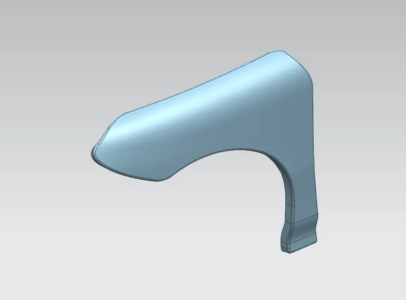
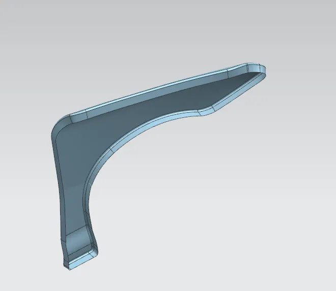
1) Drip area :
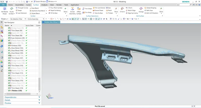
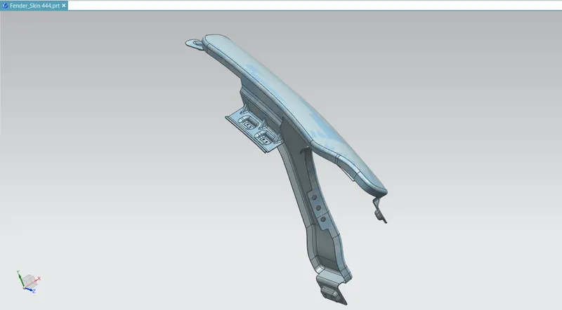
Drip area :
1)The height of drip area mounting should be less than 40mm so that it reduces the springback effect during manufacturing .
2)The edge of the mounting part should be atleast 10mm away from the nearby components in the engine .
3)It should be distanced atleast 150mm from the front side ande 200m from the rear side .
4)Ribs should be provided in order to increase the strength of the mounting part .
4)Bead is provided at the outeredge to increase the rigidity of part .
A-pillar:
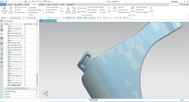
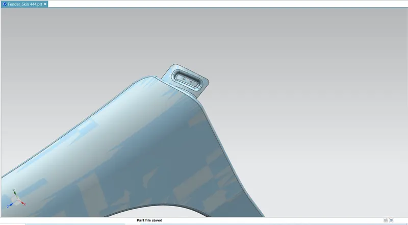
1)Ribs are provided in order to increase the strength of A-pillar mounting point .
2)Other factors for the mounting flange will depend upon the A-pillar design of car .
Bumper :
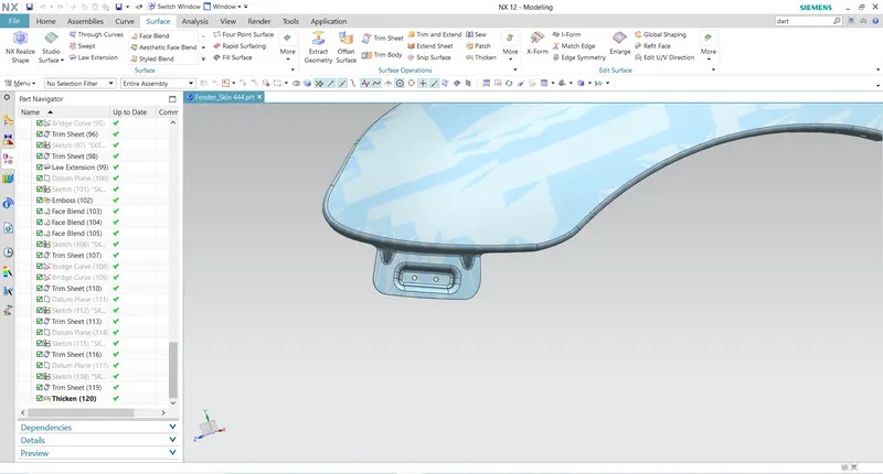
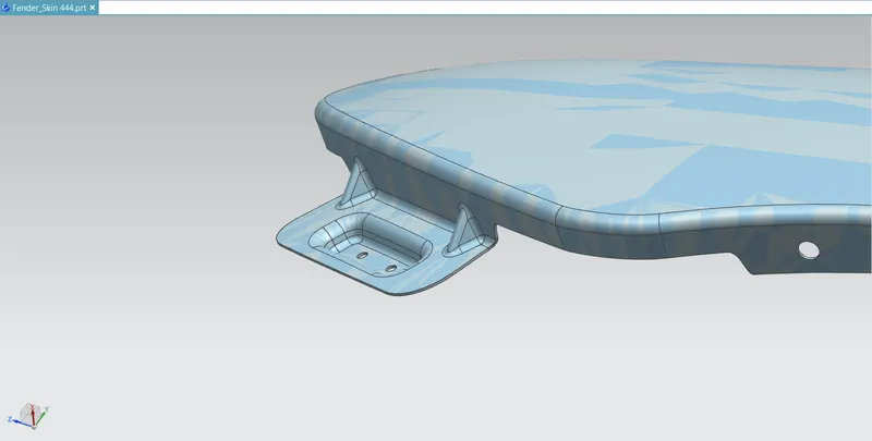
Sill area mounting :
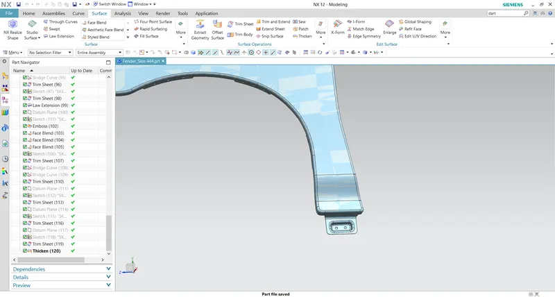
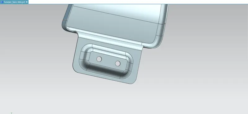
Baffle mounting :
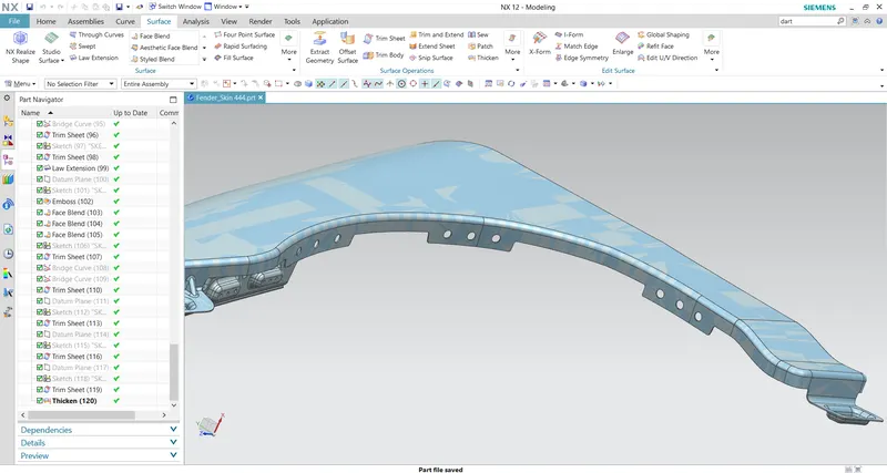
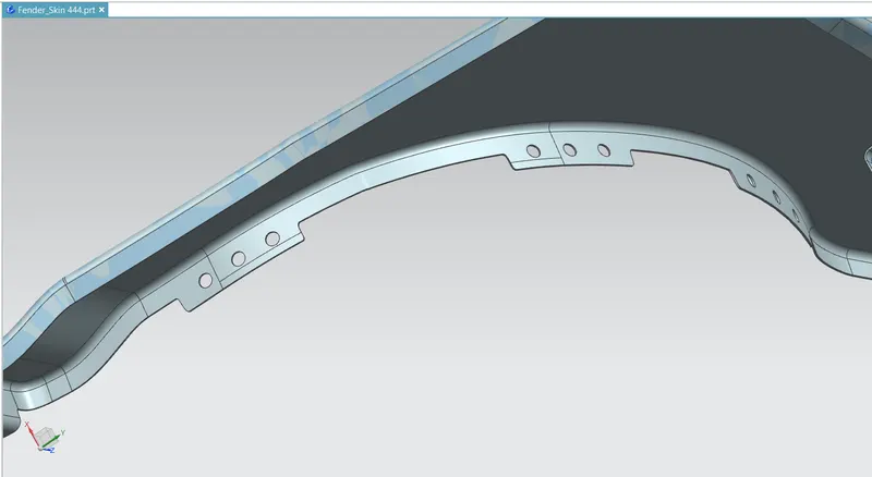
*For improvement of NVH in car , usually a baffle is mounted on the fender of the car . it is mounted on the wheel arch area .
Note - All the sketches should be fully constrained .
- Distance should be maintained between two holes following the design rule of 2*r (radius of hole) or more than 2r .
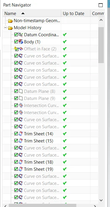
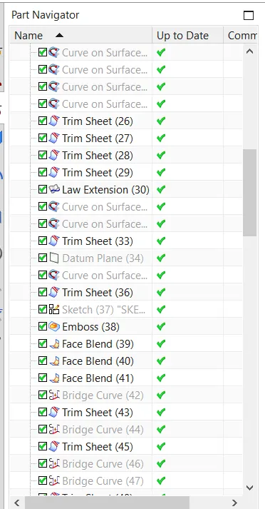
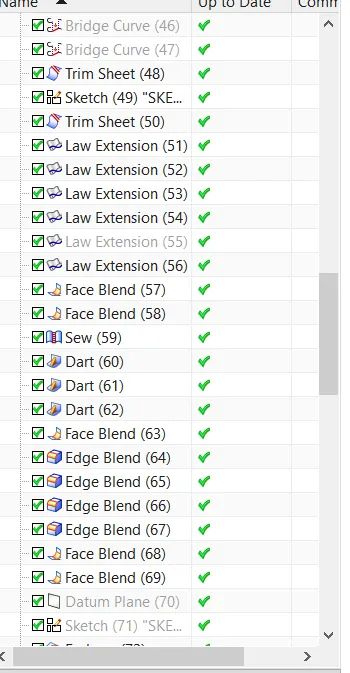
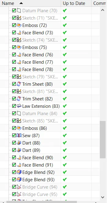
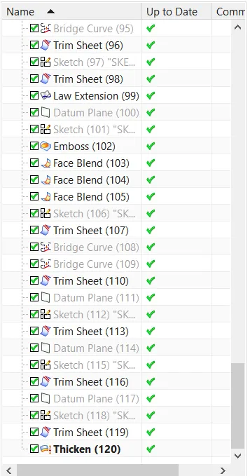
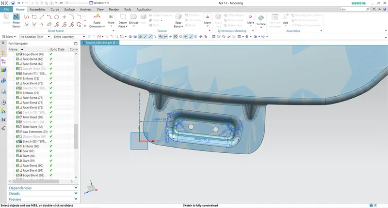
output:
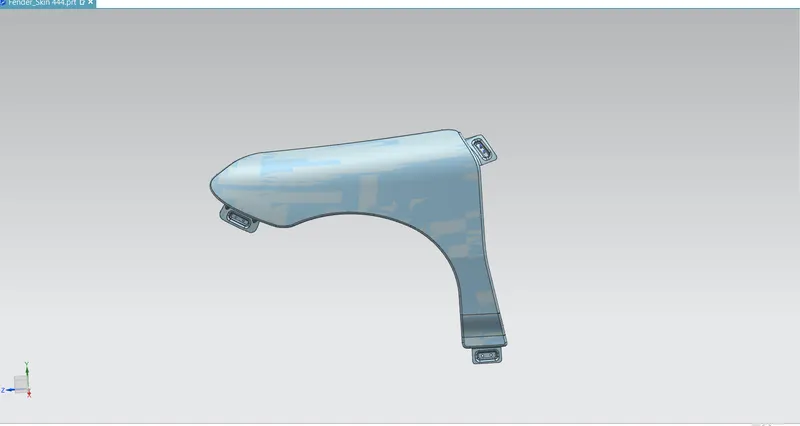
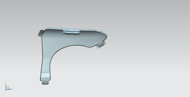
CONCLUSION :
We have developed front fender with mounting points following the design parameters and mastersection .