Fender Design Challenge
AIM: To design an automotive BIW front fender using Siemens NX - CAD
INTRODUCTION:
Fender is the American English term for the part of an automobile, motorcycle or other vehicle body that frames a wheel well (the fender underside). Its primary purpose is to prevent sand, mud, rocks, liquids, and other road spray from being thrown into the air by the rotating tire. Fenders are typically rigid and can be damaged by contact with the road surface.
Sticky materials, such as mud, may adhere to the smooth outer tire surface, while smooth loose objects, such as stones, can become temporarily embedded in the tread grooves as the tire rolls over the ground. These materials can be ejected from the surface of the tire at high velocity as the tire imparts kinetic energy to the attached objects. For a vehicle moving forward, the top of the tire is rotating upward and forward, and can throw objects into the air at other vehicles or pedestrians in front of the vehicle.
TYPES OF AUTOMOTIVE FENDERS:
FRONT AND REAR FENDERS:
FULL BUMPER FENDER: In olden days these kind of fenders were used. But in todays manufacturing scenario these fenders are no more used. The main reason is these fenders require more raw material, which increases the cost of manufacturing, impacts overall structural body weight, less crash absrbing areas, occupies more space.
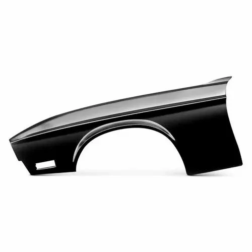
HALF BUMPER FENDER: These fenders are widely used nowadays. The main advantage of half fenders is, lightweight, absorbs more forces during any crash or impact scenarios there by saving the passengers inside the vehicle, less usage of material( we can manufacture two half fenders with the same amount of material required to manufacture one full fender, reduces manufacturing costs, processing time, also reduces the material usage.
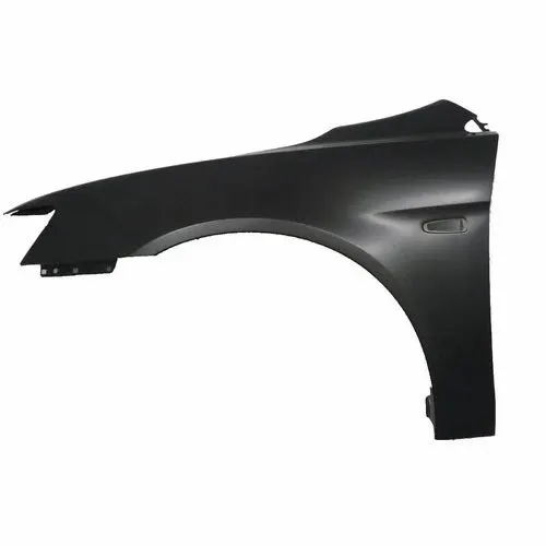
MATERIALS USED IN FENDER MANUFACTURING: The main materials used for manufacturing automotive BIW parts are steel, aluminum, magnesium, copper, plastics, composites, rubber, glass, fabric/leather and a few more. These materials have been around for quite some time but have evolved greatly and diversely.
MANUFACTURING PROCESS OF A FENDER:
The manufacturing process includes the following steps that,
Firstly, unfolding and shearing are carried out on a plate, wherein a proper cold roll specification is selected at first, a cold roll is unfolded, and then the unfolded cold roll is sheared to an iron plate of the corresponding size according to production material specifications.
Secondly, oil pressing and punching are carried out, wherein the iron plate is extended at first, then side shearing and punching are conducted on the iron plate, folding and shaping are carried out on the iron plate, and finally reshaping is carried out on the iron plate.
Thirdly, small first parts of the fender are machined, wherein first of all, the iron plate is punched to a needed outer contour blank, then the iron plate completing the outer contour blank is further shaped, and the iron plate is punched at last.
Fourthly, installation and welding of a metal plate are conducted.
The manufacturing process for the car fender is simple and high in production efficiency; a body of the fender and the small parts can be separately machined, so waiting time is shortened; working efficiency of production is improved.
DESIGN CONSIDERATIONS FOR FENDER:
- The gap between rear end of fender and front end of fender.
- At rear end we have wiper unit mounted on it, so a minimum of 200mm space should be given.
- At front end we have light housingg for which we need to give a minimum of 150mm space.
- The above two considerations are generalized over the period based upon the experiences and issues faced by automotive fender design engineers.
- Baffles are added to reduce/improve NVH and also gives strength and toughness to the fenders during vibrations.
- Embosses and darts are given to increase the strength of mountings.
- The corners/ sharp edges are smoothened/fillets in order to make manufacturing process easier and also by making sharp edges into curved edges we reduce the stresses acting at corners.
- The final thickness of the fender is taken as 0.75mm.
The skin data and master section data are provided and from the given data I have designed various mountings for the fender like A-pillar, bumper, sill, drip area, spash cover/wheel well.
FENDER SKIN/MASTER DATA:
DESIGN CONSIDERATIONS FOR DRIP AREA MOUNTING:
TOOLS USED IN FENDER DESIGN PROCESS: Tools like line,circle,rectangle,dimension,curves,splines,curve on suface,projection curve,intersection curve,bridge curve,offset curve in face,datum planes,face blend,edge blend,law extension,trim sheet, trim and extend,extend sheet,sew,thicken,emboss,dart,A text,local radius analysis are used during the design process of a fender.
DRIP AREA MOUNTING:
SPLASH COVER MOUNTINGS:
A-PILLAR MOUNTING:
BUMPER MOUNT:
SILL MOUNT:
FINAL FENDER DESIGN VIEWS:
CONCLUSION: Hence the fender is designed as per the mentioned dimensions and design considerations using NX-CAD.