Fender Design (BIW) Using Siemen NX
- DESIGNING OF FRONT FENDER (BIW) -USING SIEMEN NX
OBJECTIVE
The main objective of this project is to learn the Basics of the BIW (Body in white) through designing the Front Fender “ of a car by considering all the Protocols and Standards of BIW Design.
INTRODUCTION
What is BIW?
Body in white (BIW) is the stage in automobile manufacturing in which a car body's frame has been joined together, that is before painting and before the motor, chassis sub-assemblies, or trim (glass, door locks/handles, seats, upholstery, electronics, etc.) have been integrated into the structure. Assembly involves different techniques such as welding (spot, MIG/MAG), riveting, clinching, bonding and laser brazing. Body in white refers to the stage in automotive manufacturing when a car’s sheet metal components are welded together which include:
- Hood
- Trunk lid
- Roof
- Front and rear Fender
- Side wall
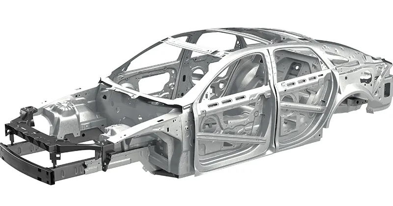
The term BIW derives from manufacturing practices before steel unibody monocoques — when automobile bodies were made by outside firms on a separate chassis with an engine, suspension, and fenders attached .The manufacturers built or purchased wooden bodies (with thin, non-structural metal sheets on the outside) to bolt onto the frame. The bodies were painted white prior to the final color.
A folk etymology for "body in white" is the appearance of a car body after it is dipped into a white bath of primer (undercoat paint)— despite the primer's actual gray color. BIW could also refer to when car bodywork would be made of timber - all timber products, furniture, etc., are considered to be "in the white" when at the stage of raw timber before finishing or varnishing.
In car design, the "body in white" phase is where the final contours of the car body are worked out, in preparation for the ordering of the expensive production stamping die. Extensive computer simulations of crash-worthiness, manufacturability, and automotive aerodynamics are required before a clay model from the design studio can be converted into a body in white ready for production
What is a Fender ?
Fender is the American English term for the part of an automobile, motorcycle or other vehicle body that frames a wheel well (the fender underside). Its primary purpose is to prevent sand, mud, rocks, liquids, and other road spray from being thrown into the air by the rotating tire. Fenders are typically rigid and can be damaged by contact with the road surface.
Sticky materials, such as mud, may adhere to the smooth outer tire surface, while smooth loose objects, such as stones, can become temporarily embedded in the tread grooves as the tire rolls over the ground. These materials can be ejected from the surface of the tire at high velocity as the tire imparts kinetic energy to the attached objects. For a vehicle moving forward, the top of the tire is rotating upward and forward, and can throw objects into the air at other vehicles or pedestrians in front of the vehicle.
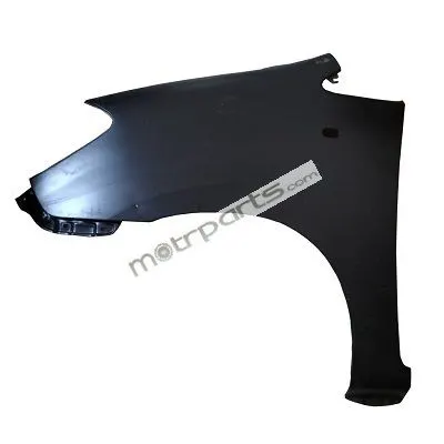
In current US auto industry nomenclature, usually only the panels over the front wheels are called fenders. The auto industry changed from rear fenders bolted onto a quarter panel to an enlarged welded-on quarter panel that fulfilled both functions. This resulted in one piece where there had previously been two, and name of the larger welded piece, the quarter panel, survived the consolidation. Quarter panels are at the rear, with an exception made for dual rear wheel trucks, where the panel at the rear is called a fender. For vehicles with a narrow car body that exposes the tire, the fender is an exposed curve over the top of the tire. For wide body vehicles that cover the tire, the fender forms the wheel well surrounding the tire, and is not directly visible from above the car body.
There are two types of fenders which are Half Bumper type fender and the Full Bumper type fender.
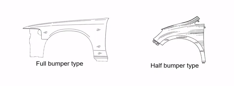
Among this the most commonly used fender type is the half Bumper type. Because For manufacturing the half bumper type fender , it only need about the half of the sheet metal needed for the Full bumper type. Thus it reduces the material usage there by reduce in the cost as well as the weight of the car.
DESCRIPTION
In this project we are going to create the Front Fender using a previously given Styling surface as the reference. The software used here to model the Fender is Siemens NX
For creating a fender, there are several Factors and standards a Design engineer should consider . There are four mountings usually present in a fender of a car except the baffle mountings. They are the Drip , Sill Mounting , A pillar mounting and the Bumper mounting
Before the designing the first thing we need to consider about is the material selection
Material selection
BIW is expected to possess a number of significant properties. It must have high tensile strength as well as high stiffness—bending, torsional, static, and dynamic. It must also provide good quality safety both to the car body and to its occupants against crashes of all kinds—front, rear, side, or even rollover, meeting the Federal Motor Vehicle Safety Standard No. 208 [44]. It should also be able to protect occupants from noise, vibration, and/or harshness (NVH) by absorbing or reducing these conditions. Also, it should be easy to weld and form, as well as be highly paintable and easy to design. It should provide a good surface finish that is smooth, and should also be corrosion resistant. Improvement of fuel economy also necessitates the use of lightweight materials in BIW, as it constitutes a significant share of car’s weight; in addition, given environmental concerns in recent times, it is also expected to be recyclable. Given such extensive requirements, only steel and aluminum have been used for making BiW; the former is preferred for its high strength and low cost, while the latter is preferred for its lower density that helps reduce car weight

|
Material |
Yield Strength (MPa) |
Ultimate Tensile Strength (MPa) |
Reference |
|
Steel |
210–1250 |
340–1520 |
[46] |
|
Aluminum |
90 |
195 |
[47] |
|
CFRP |
250–585 |
[48] |
Here we are assuming Stainless steel as the material for the Designing of Hood
Designing of the mountings
In this project we are mainly dealing with the designing of the four mountings of a fender which are the Drip area , A pillar mounting , Sill mounting and the Bumper mounting.
There are some considerations we must take care of , while the designing.
- The holed surfaces where the fasteners should used, must be flat.
- A 5 mm flat surface should be maintained around the holes for the fasteners.
- Darts and Beads must be used in proper bends in-order to maintain strength of the mountings.
Among these mountings the most critical mount is the Drip area , where there are some extra factors to consider. For creating the drip mount the location of the A-pillar mount must be known. So first we need to create the A- pillar mounting.
- A- pillar mounting
A pillar mounting is the area where the fender attaches the A -pillar using fasteners.
Here I have created a 25 mm length flange and I have created 2 embosses having a plane as end cap for achieving the flat surface for the fasteners .I have also maintained 5 mm flat surface around the holes.
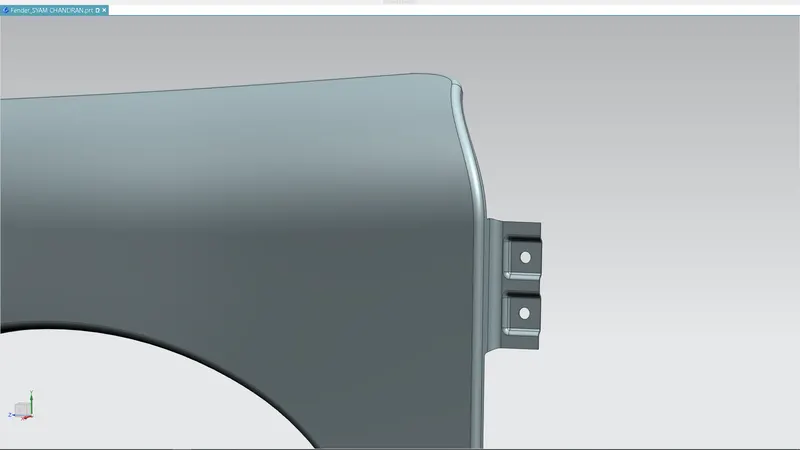
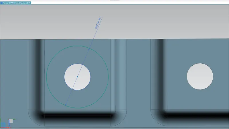
Here the hole radius is 6 mm and i have drawn a circle of radius a 14 mm concentric to the hole , shows a flat surafce of more than 5 mm is there around the hole.
- Drip area designing
Drip area is the mounting of the fender which mounts the fender to the engine compartment. The drip area is usually in between the head light housing and the cowl top. As it is in between those two components ( head light , cowl top) there are some factors to consider while the designing of the drip area .
Here I am taking a master sketch of a fender as another reference and according to that I am going to create the model.
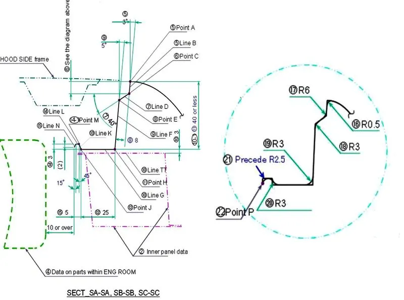
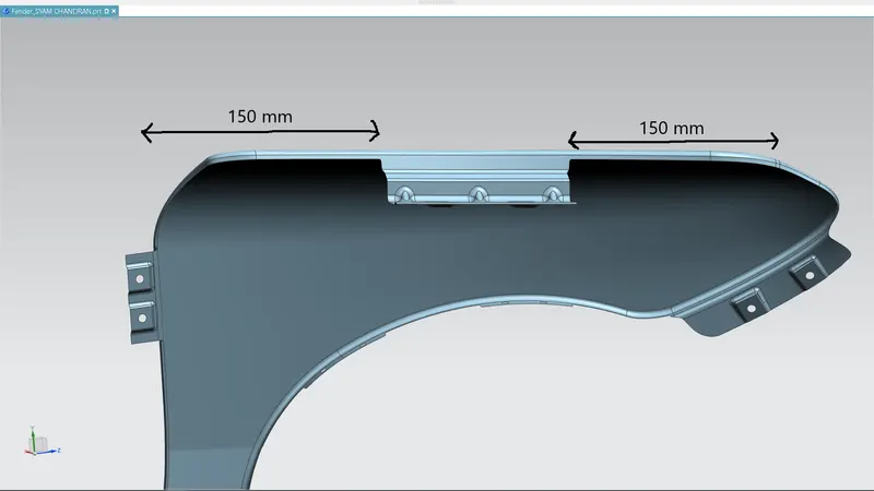
- The first factor to consider is the distance of the drip from the A pillar mounting. As shown in the master sketch , the distance from the cowl top area to the drip must be 200 mm or more. But in some cases as the size of the cowl top area decreases this distance also decrease.
- Also the distance from the head light to the drip also must be 150 mm or more.This distance is maintained for the housing of the head lights.
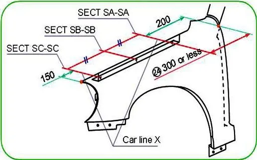
- The over all length of the drip must be 40 mm or less.More than 40 mm will cause to spring back effect at the drip area resulting in NVH.(noice , vibration and harshness)
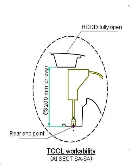
- Tool workability : A minimum length of 200 mm must be maintained in between the bottom flange of the drip and the hood of the car when it is in opened condition to ensure the easy use of tool inside the hood when adding fasteners.
- A 10 mm or more distance must be maintained from the engine room to the end of the Drip area
- Surface for the fasteners must be flat
As we are creating a small fender with congested cowl top area , we are taking the drip to cowl top area distance to 150 mm instead of 200 mm.
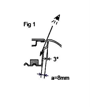
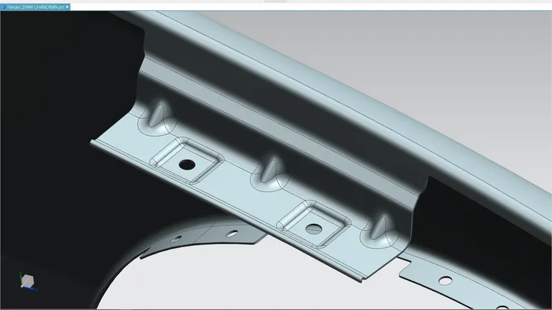
Here I have created an extra flange as shown in the figure in order to prevent the direct view of the fasteners and the inner area of the drip.
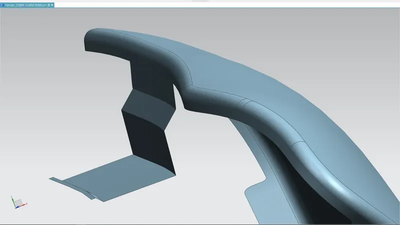
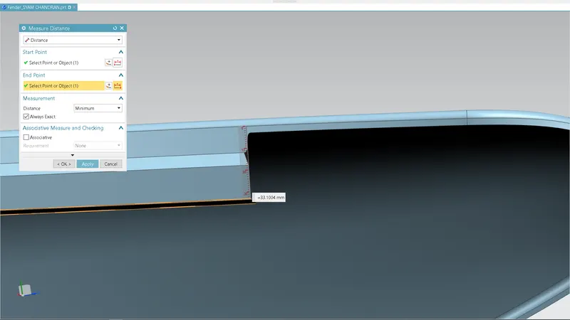
I have taken 33.1 mm as the whole length of the Drip area
As i doesn’t have the engine room data I am not worried about the 10 mm distance of drip from the engine room and also the tool clearance
Like I did in the a pillar mounting , here I have created 2 embosses to achieve the flat surface for the fasteners . Also i have added proper darts to the flanges as drip mounting have several flanges and a have more length.
At the end of the flange a small curved structure has been added in order to maintain the falnge strength.
- Sill mounting
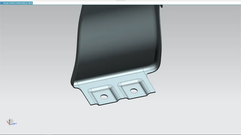
Sill mounting is Another mounting in the fender which attaches the sill to the fender using the fasteners. Same as the A-pillar mounting I have created a flange of 25 mm length and made 2 embosses with flat surfaces and also 5 mm flat surface around the hole is maintained
- Bumper mounting
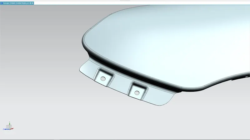
The part which attaches the bumper to the fender .Consideration for bumper mounding is same as the sill and A-pillar mounting.
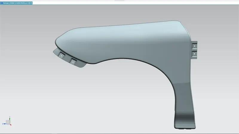
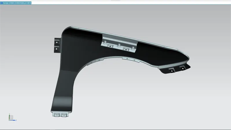
Some Views of the final model is depicted below
CONCLUSION
The Fender and its all mountings has been successfully Created by considering all the standards and parameters of BIW-fender design