Fender Design
Aim: To design the car front fender by following the Master section without violating the design parameters.
Project Overview:
Fender is the component of the car which is used to cover the front wheels of the car. In this project we are going to design the Fender from the given Class-A surface. We will follow the design rules and create the sheet metal component as per industry standards.
Theory:
Fender
Front Fender is the component of the car which is used to cover the front wheels of the car. Apart from providing the aesthetic look to the vehicle, it covers the side portion of the engine compartment and also protects the pedestrians from the chip that ejects outwards when the car is in motion.
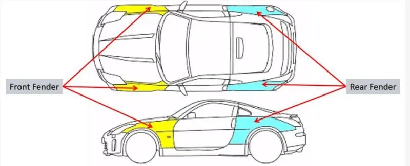
Fender Mountings
Fender is mounted on the following five major areas-
- Body/ Bumper - This mounting is done majorly on the front area.
- A-Pillar - It is the mounting done on the part between the windshield and the front window.
- Cowl - It is the portion below the windshield where the fender is mounted on its side portion.
- Sill - Sill is the lower portion of the body which runs along the wheel arch beneath the doors
- Drip - It is the area inside the engine’s compartment where the fender is mounted.
Types of Fenders
- Full-Bumper Type Fender: It extends up to the bumper.
- Half Bumper Type Fender: It is extended only upto the headlamp which allows us to attach the bumper separately.
Note: Currently we majorly use half bumper type fender in the industry which provides us two advantages
- Scrap Management - Manufacturing Full type fender results in excess of material waste as the area is large and sometimes may limit the press size. Whereas we can manufacture two Half type fenders in the same area or slightly bigger area which ultimately results in scrap reduction.
- Weight Reduction - Using half bumper type fender allows us to manufacture the bumper of completely different material other than pure metal which results in weight reduction.
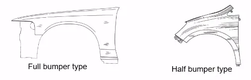
Procedure:
I] Studying the Master Section:
Master Section:
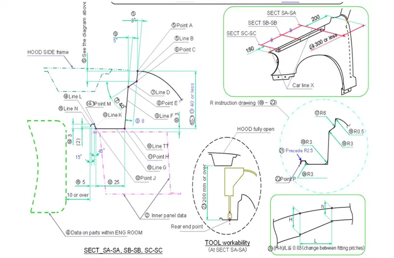
II] Creating Drip mounting area:
The most significant and important area to design the mountings for is the drip area. We have to follow a certain set of rules to design the same.
Process to create the drip mounting:
- Create the curves on the drip mounting region using Curve on Surface too such that the minimum distance from the headlamp should be 150 mm and from the cowl should be 300 mm.
- Trim off the non required regions.
- Create flanges using Law extension by following the master section dimensions
- Create Ribs using Dart command which provides strength to that area.
- Later create the emboss for mountings on the flange. The procedure for emboss creation is mentioned below.
- Create mounting holes.
- Lastly provide necessary fillets using Blend tool.
Emboss Creation:
- Create a basic sketch profile of an emboss to be made.
- Project the emboss profile on the base feature using Project Curve Tool.
- Use the Emboss feature to create the emboss.
- The End Cap of the emboss can be altered as per our requirements.End cap is nothing but your outward projected face. Here as mountings require flat surfaces we create a datum plane and use it as the end cap.
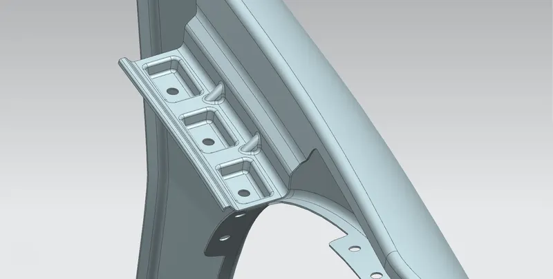
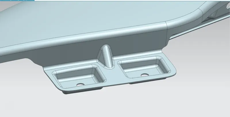
III] Bumper Mountings:
- Create the curves on the bumper mounting region using the Curve on Surface tool.
- Trim off the non required regions.
- Create flange using Law extension.
- Create Ribs using Dart command which provides strength to that area.
- Later create the emboss for mountings on the flange.
- Create mounting holes.
- Lastly provide necessary fillets using Blend tool.
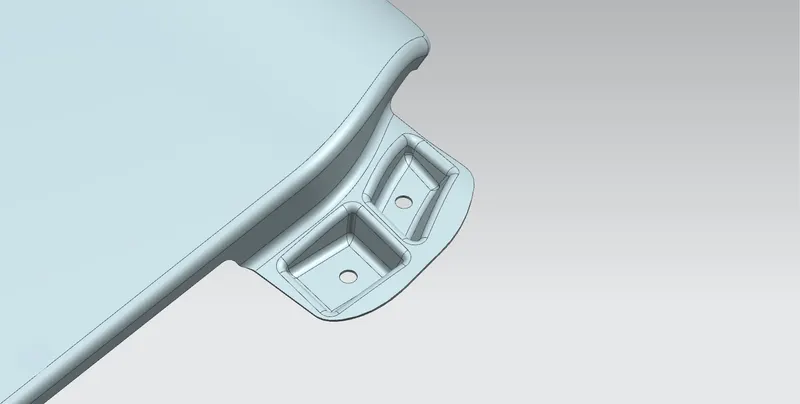
IV] A-Pillar Mountings:
- Create the curves on the bumper mounting region using the Curve on Surface tool.
- Trim off the non required regions.
- Create flange using Law extension.
- Later create the emboss for mountings on the flange.
- Create mounting holes.
- Lastly provide necessary fillets using Blend tool.
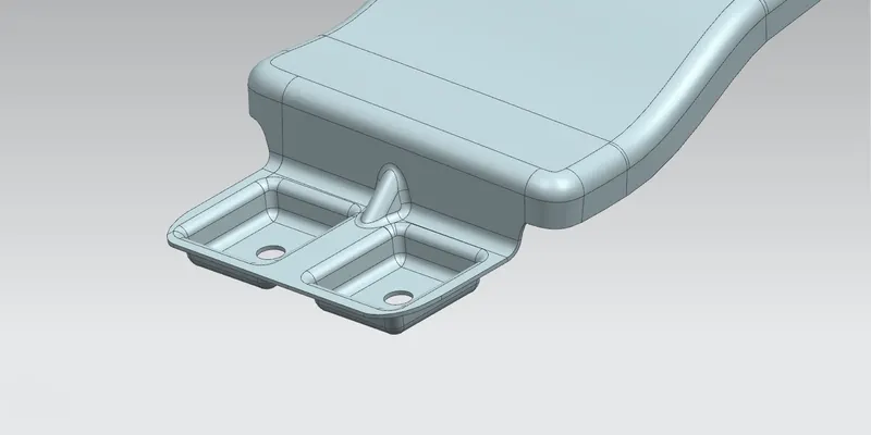
V] Sill mountings:
- Create the curves on the bumper mounting region using the Curve on Surface tool.
- Trim off the non required regions.
- Create flange using Law extension.
- Later create the emboss for mountings on the flange.
- Create mounting holes.
- Lastly provide necessary fillets using Blend tool.
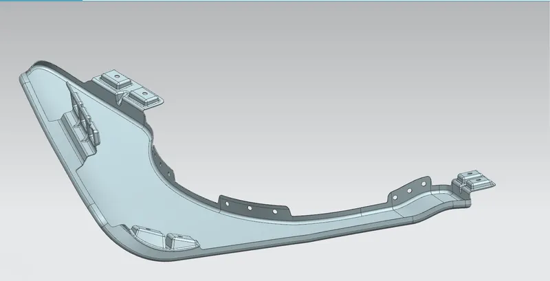
VII] Baffle Mounting:
Baffle is a plastic component which helps in improving NVH reduction.
Process to create the baffle mounting:
- Create the curves on the bumper mounting region using the Curve on Surface tool.
- Trim off the non required regions.
- Create mounting holes.
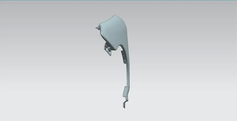
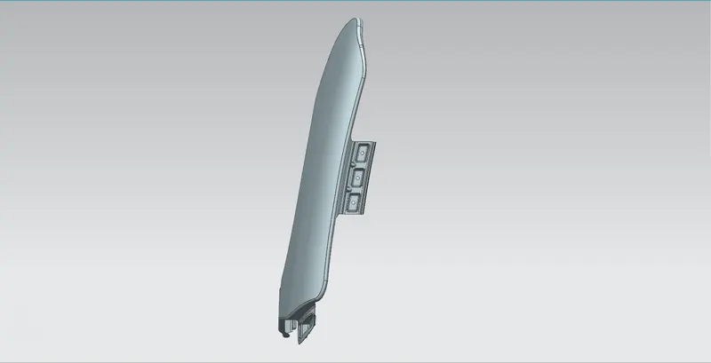
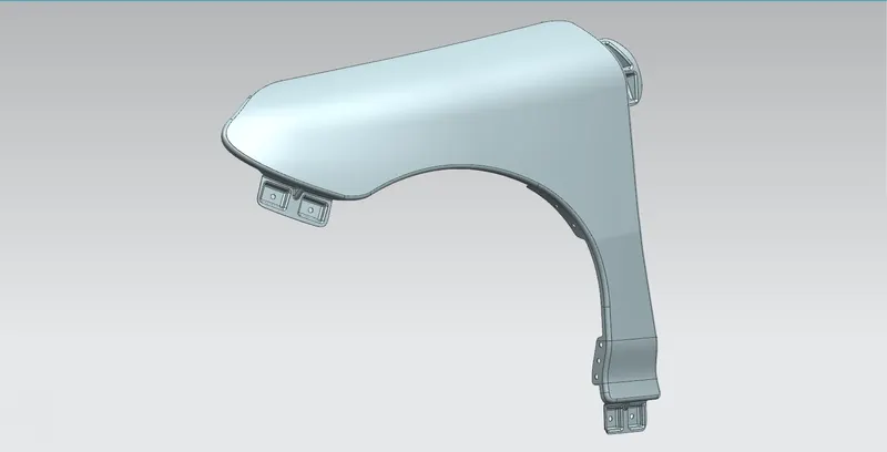
Component Formed:
Front View:
Top View:
Isometric View:
Conclusion:
Hence we have successfully completed the design of Fender by following proper industry standards and design rules.