Fender Design
FENDER DESIGN
INTRODUCTION:
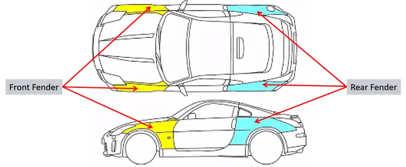
The fender is an important component on the exterior of the car as it houses the wheel arch which in turn houses the vehicles wheels. The wheel should ideally sit inside the boundaries of the fender to avoid the it from spraying abrasive particles into the air which could potentially cause damage, in the form of chipping to the exterior components of the vehicle or these same particles could be flung onto pedestrians, which again is dangerous.
The fender's openings for the wheel wells tend to be much larger than the diameter of the tire, because they do not move with the tire suspension and consequently must be large enough to allow the full range of tire motion on the suspension without touching the interior of the wheel well.
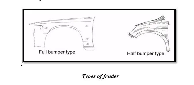
FENDERS ARE CLASSIFIED INTO TWO TYPES:
· Full Bumper type.
· Half Bumper type.
Full Bumper:
The below image is the example of full bumper type fender which is used during the initial stage of automotive design and it is having huge size when compared to the half bumper type and the die for producing this full bumper is large and have more scrap after the press or emboss process.
It purely depends on the OEM which they decide whether to use Full bumper type or Half bumper type. It will increase the blank cost and it will be reflected in cost of the car.
Half Bumper type:
The below image is an example for half bumper type which will require smaller die area compared to the full bumper type and even we can produce two fenders in one die just by increasing the size of the die and scrap will also be reduced. It will decrease the blank cost and it will be reflected in cost of the car. In addition to that weight reduction with increased perfomance of the car.
DESIGN REGULATION’S NEED TO CONSIDER:
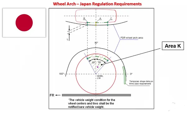
Considering the factor of pedestrian safety, there are certain regulations set by the different automotive bodies around the world when it comes to this safety factor.
Although all of them state that the tire & wheel should sit inside the boundaries of the fender, there are slight variations on the distance the tires must be offset from the fender boundary depending on the different automotive governing bodies based on the road conditions of that specific region.
Other consideration:
· Design requirements for the fender and its components.
· Functional requirements.
· Region Standards.
· Drip Area.
· Wheel Arch.
· Baffle and Outside Rear View Mirror (OVRM) mounting.
· Frontal crash regulations and requirement.
· Gap and Flushness requirement.
MANUFACTURING PROCESS
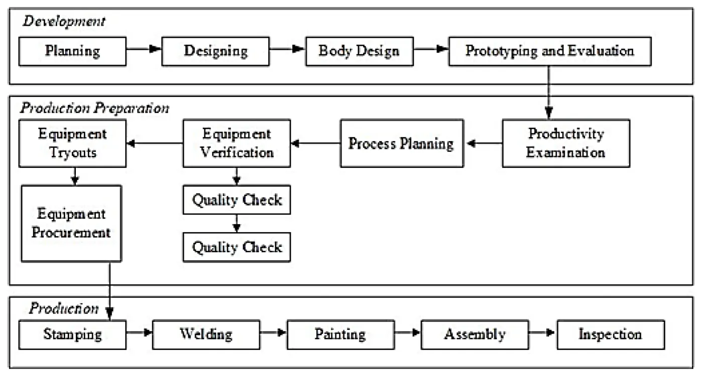
· Firstly, unfolding and shearing are carried out on a plate, wherein a proper cold roll specification is selected at first, a cold roll is unfolded, and then the unfolded cold roll is sheared to an iron plate of the corresponding size according to production material specifications.
· Secondly, oil pressing and punching are carried out, wherein the iron plate is extended at first, then side shearing and punching are conducted on the iron plate, folding and shaping are carried out on the iron plate, and finally reshaping is carried out on the iron plate.
· Thirdly, small first parts of the fender are machined, first of all, the iron plate is punched to a needed outer contour blank, then the iron plate completing the outer contour blank is further shaped, and the iron plate is punched at last.
· Fourthly, installation and welding of a metal plate are conducted.
DESIGN METHODOLOGY:
There are 5 Mounting regions in a fender:
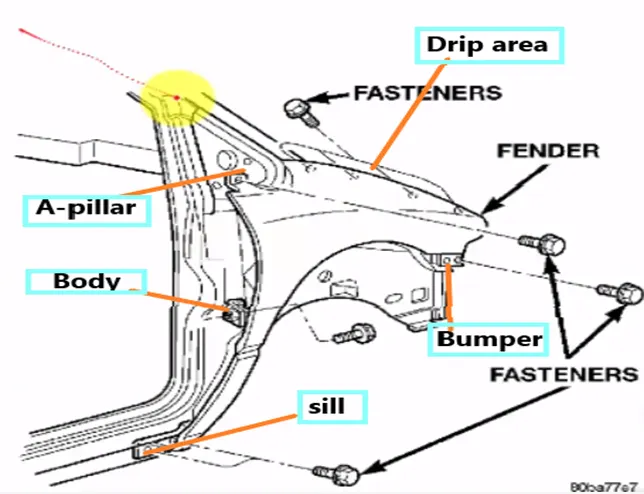
· Body
· A pillar
· Sill
· Cowl
· Drip
DRIP AREA:
The drip area mounting is the most important mounting in this challenge and was the dimensioning of it was very carefully considered as this is the area that is mounted inside the engine bay and hence has more design constraints than the other mounting regions.
Master section:
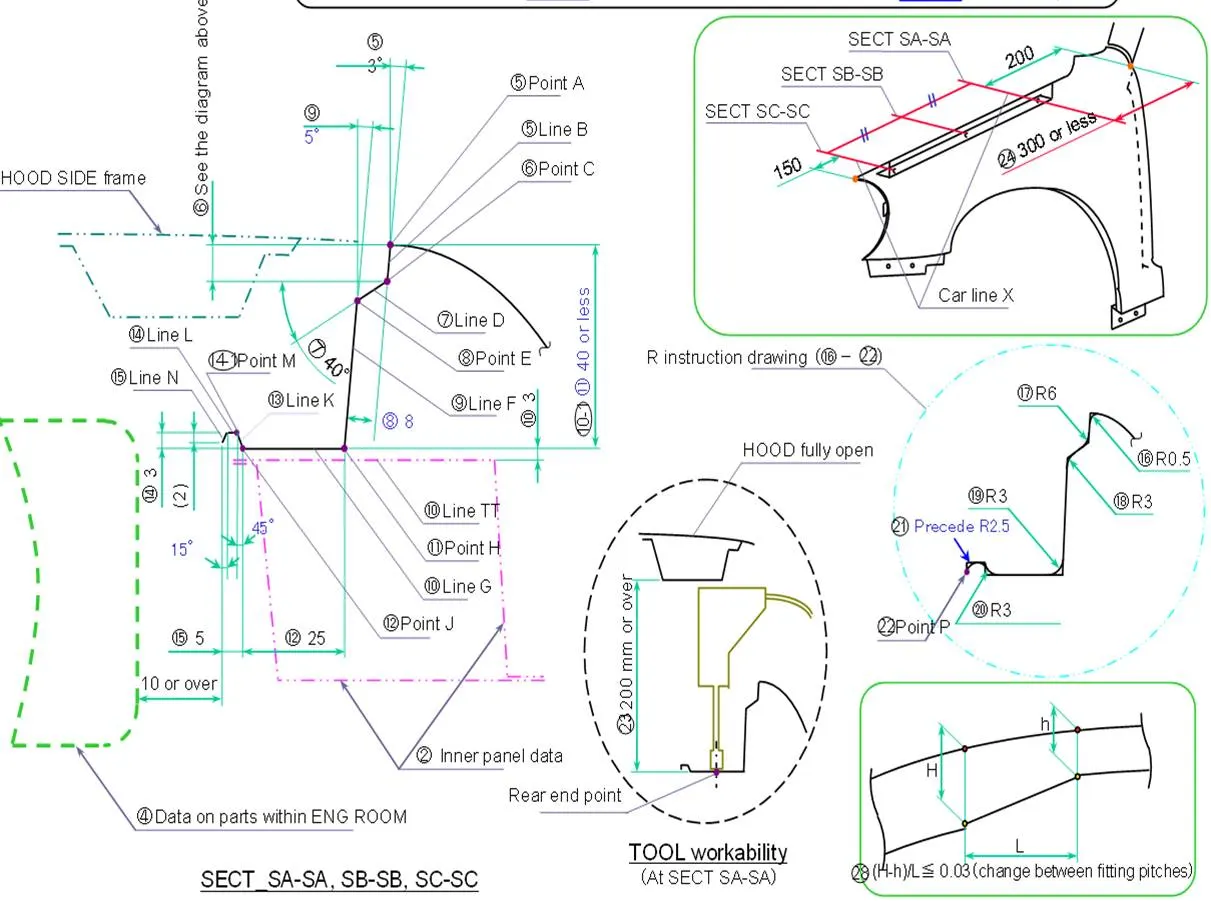
· From the backside of the fender, we provide 200mm clearance for cowl mounting,
· From the front the side we provide 150mm clearance for the head lamp.
· Create drip area according to the master section given.
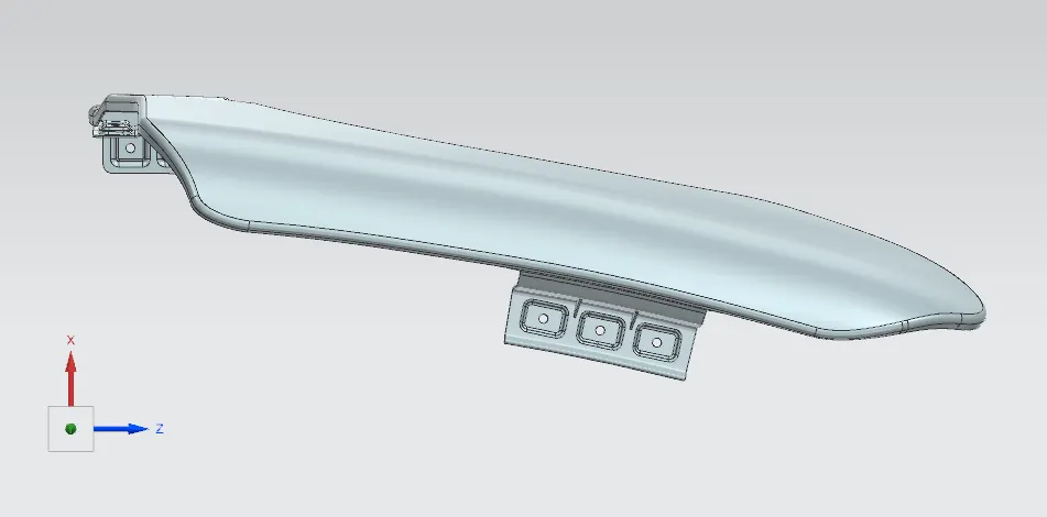
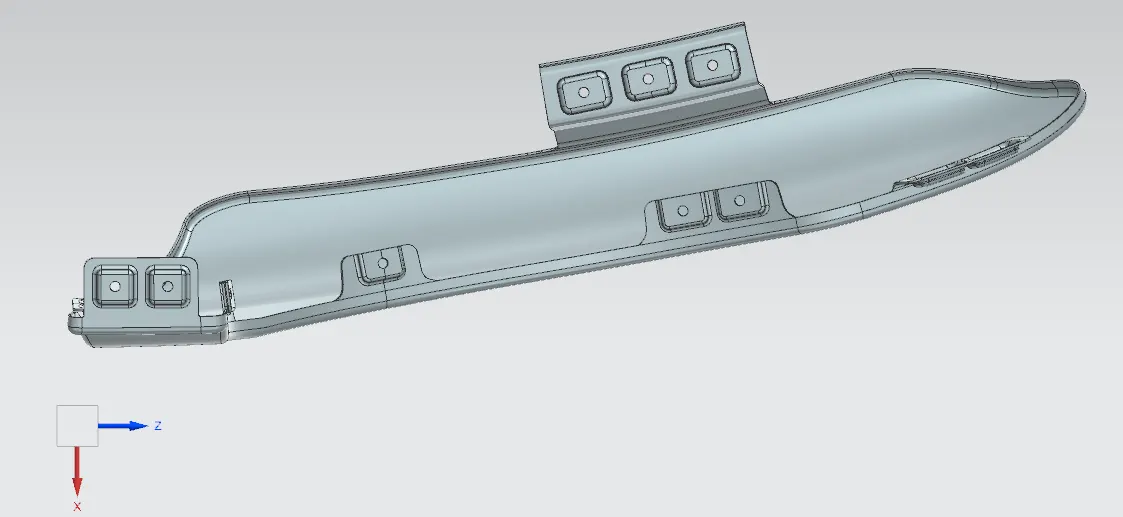
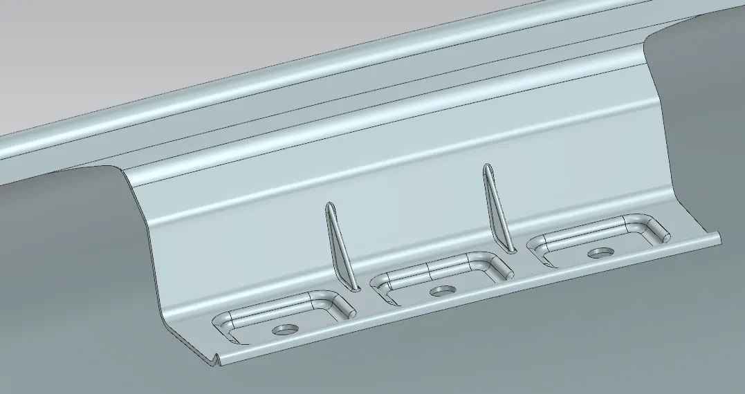
· Ribs are added on the drip area to provide the stiffness and add strength to the part. This helps the fender to not to vibrate.
· Embosses are provided on the drip area for strengthen the fastening area.
A PILLAR MOUNTING AREA:
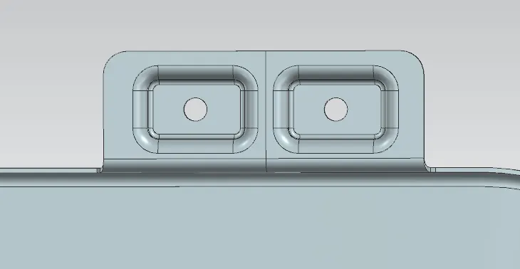
The A-Pillar mounting, as the name suggest is the area where the fender is mounted onto the A-Pillar of the vehicle. There is no exact area for this mounting as the pillar runs through the vertical side of the fender. This mounting has also been provided with embosses for the strengthening them as it is the only mounting point in this part of the fender.
BUMPER MOUNTING AREA:
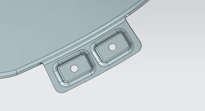
The Bumper mount sits in the front most portion of the fender, as the bumper comes in front of the fender and it will be easier to mount if the mounting points are right at the front. Regular fasteners are used to hold the bumper in place with the fender.
SILL MOUNTING AREA:
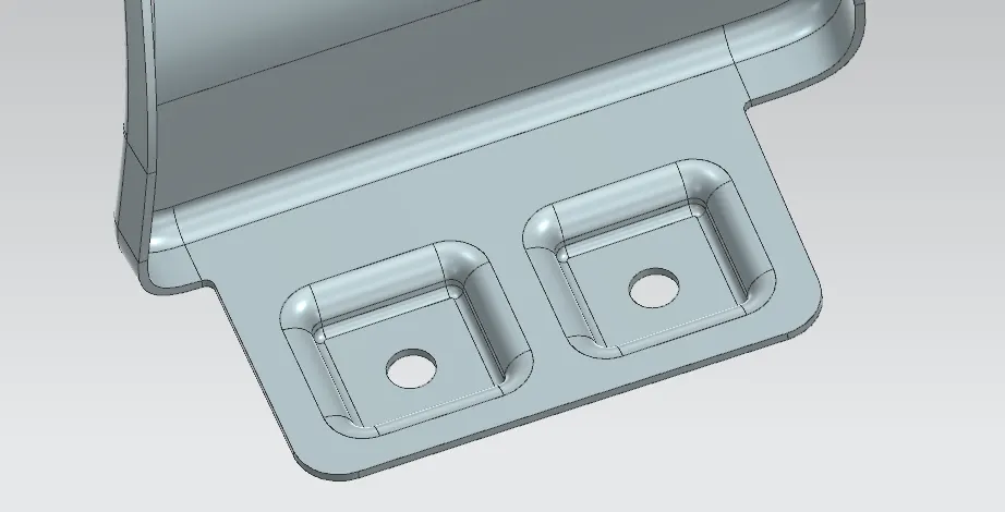
The sill mount or also known as the floor mount, is the bottom most region of the fender that mates with a portion of the floor of the vehicle. This is the only mounting provided in this region and hence it is strengthened with embosses so that it can be bolted down firmly in place.
BAFFLE MOUNTING:
The Baffle mounting or the otherwise known as the splash mounting, is the in the wheel well which houses the wheel arch. This is the component in the fender that actually protects the engine bay from chipping from the particles that are thrown in the air by the rotation of the tyres.
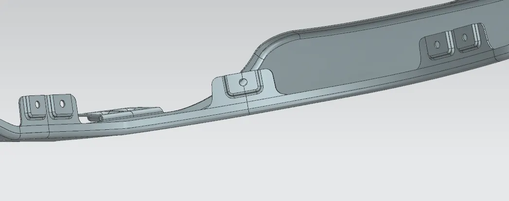
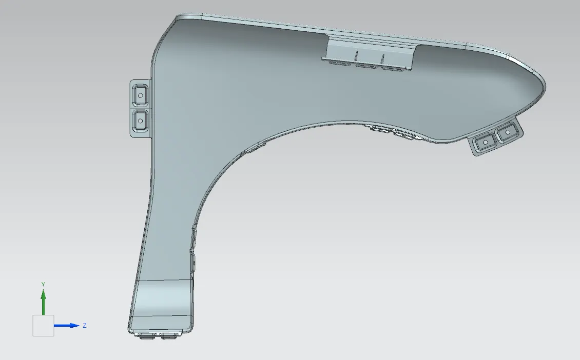
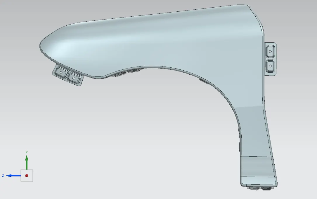
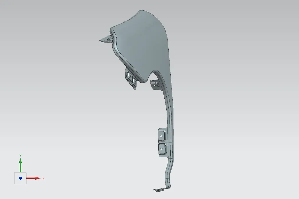
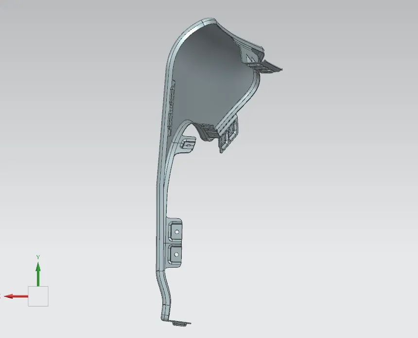
PICTURE OF MODEL IN DIFFERENT VIEWS: