Fender Design
Aim:-
To Design a front fender from the given skin data and the master section provided with Drip mounting, A-pillar, Sill, Bumper and Baffle (splash) Mounts.
Description:-
From the Given skin data to create the mountings of the fender with respect to the design consideration and with respect to the provided mastersections.
FENDER:-
Fender is the US english term for the part of an automobile that frames a wheel well. Its primary purpose is to protect from the stones,sand,mud,liquids and other road spray from being thrown away into air by the rotating tire. When the vehicle is moving tires pick up stones and the other things . hurl them in all directions.
Fenders are basically present to prevent injuries to the pedestrians and contain the motion of these particles
Before we are going to design the fender we need to ensure the following criteria's are considered:-
- Design requirements for the fender and its components.
- Functional requirements.
- Important regulations.
- Drip Area.
- Wheel Arch.
- Baffle and Outside Rear View Mirror (OVRM) mounting.
- Frontal crash regulations and requirement.
- Gap and Flushness requirement.
Fenders are classified into two types:-
- Full Bumper type.
- Half Bumper type.
Full Bumper:-
The above image is the example of full bumper type fender which is used during the initial stage of automotive design and it is having huge size when compared to the half bumper type and the die for producing this full bumper is large and have more scrap after the press or emboss process. It purely depends on the OEM which they decide whether to use Full bumper type or Half bumper type. It will increase the blank cost and it will be reflected in cost of the car.
Half Bumper type:-
The above image is an example for half bumper type which will require smaller die area compared to the full bumper type and even we can produce two fenders in one die just by increasing the size of the die and scrap will also be reduced. It will decrease the blank cost and it will be reflected in cost of the car. In addition to that weight reduction with increased perfomance of the car.
Functional requirements for the mounting of the front fender:-
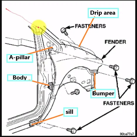
There are 5 Mounting points in a fender
- Body
- A pillar
- Sill
- Cowl
- Drip
Drip Area Mastersection data:-
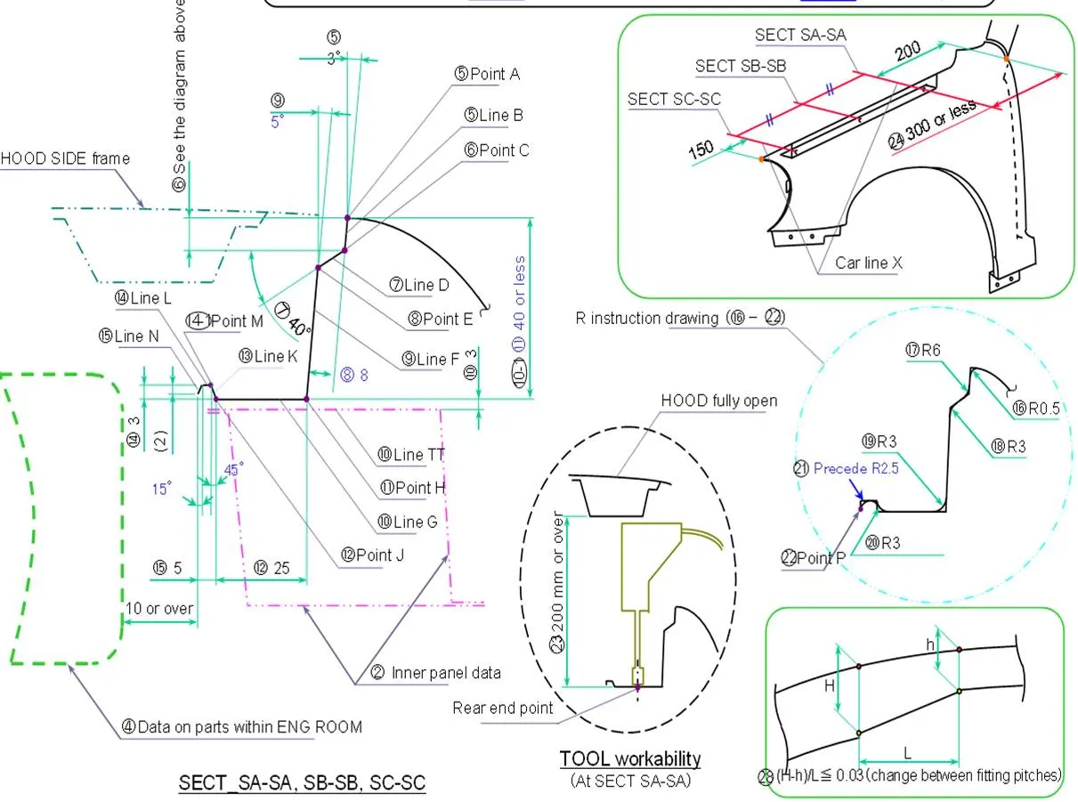
The above image is the master section data for the drip area in the fender. It is the most important part in fender mounting.
For creating the drip area we need to have minimum clearance of 150mm from the front side and 200mm from the rearside as per the mastersection , the gap is for the head lamp housing fixations in the front side and for the wiper motor below the cowl region for the rear side. It varies according to the industry standards.
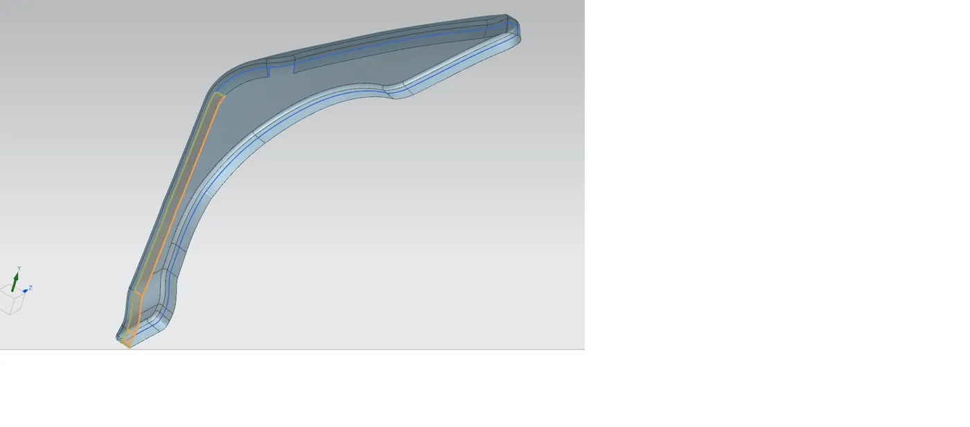
To create the A pillar mounting in the fender created couple of curves on the surface and made a trim to have a smooth cutout for the A pillar and with that surface created a law extension perpendicular to the curve.
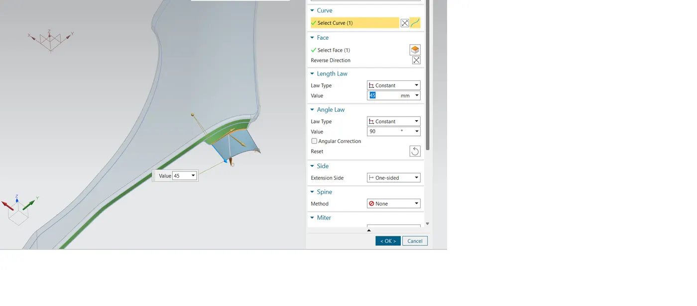
After creating the law extension, datum planes are created with the help of A pillar mounting as reference or starting point for the rear end clearance of 200mm for the wiper motor which will be the rear side of the drip area and from the front side taken reference from the curve area for the 150mm front side clearance of the drip area.
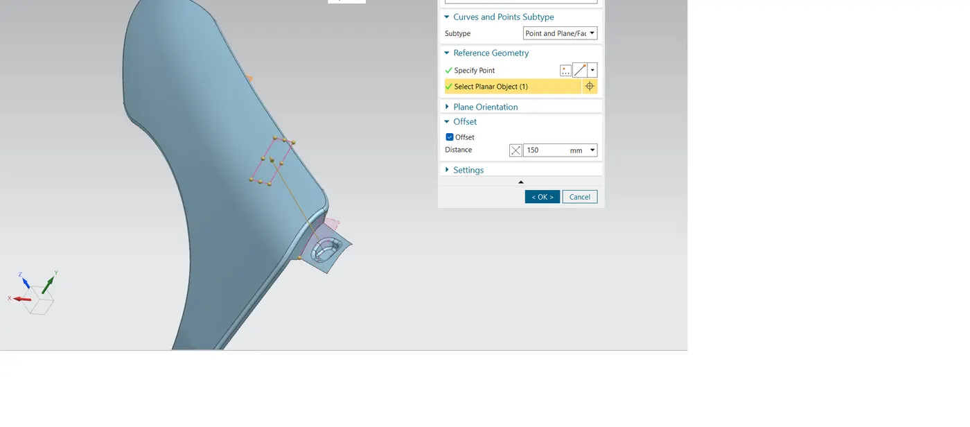
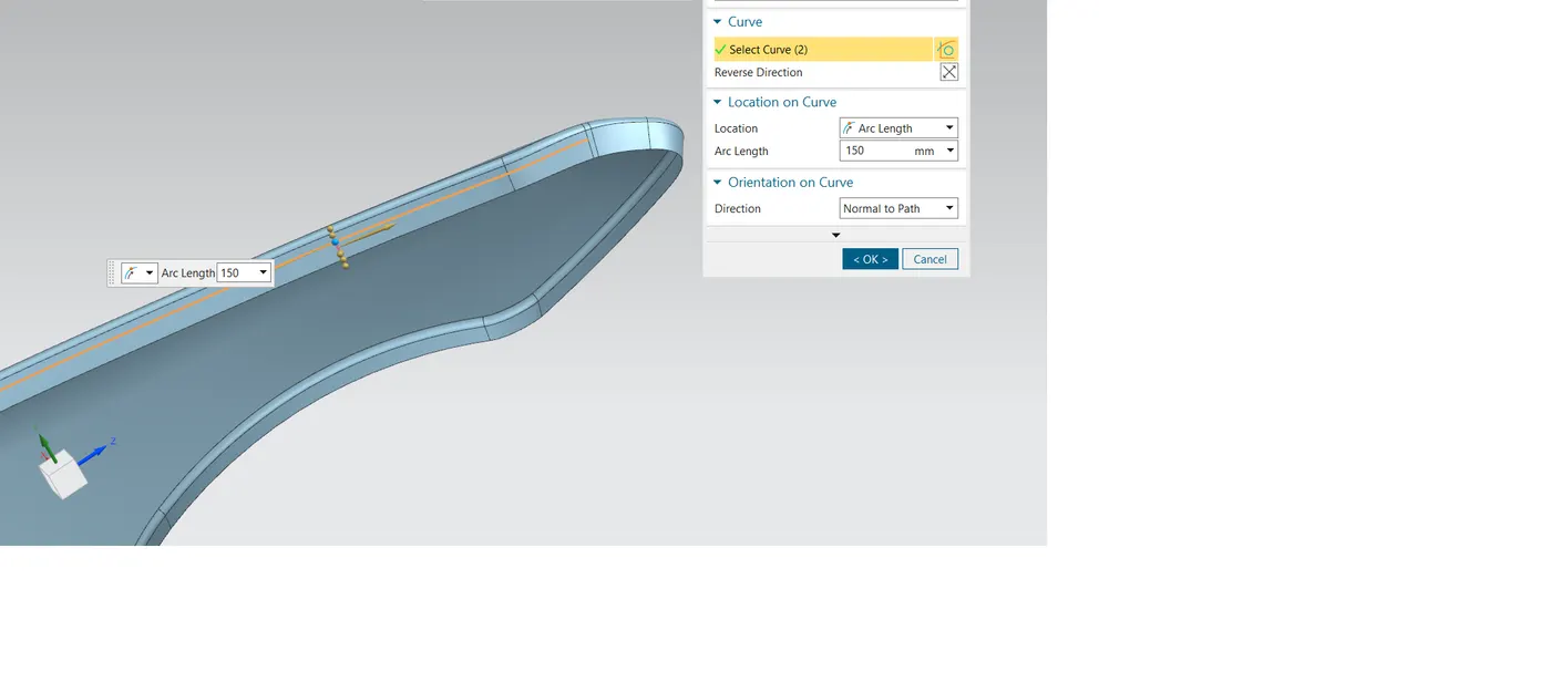
After that created the intersection curve with respect to the plane and using curve on surface command create smooth profile for the drip area. Trimmed the sheet according to that (front side upto bumper mountng)(rear side upto A pillar & Sill mounting).
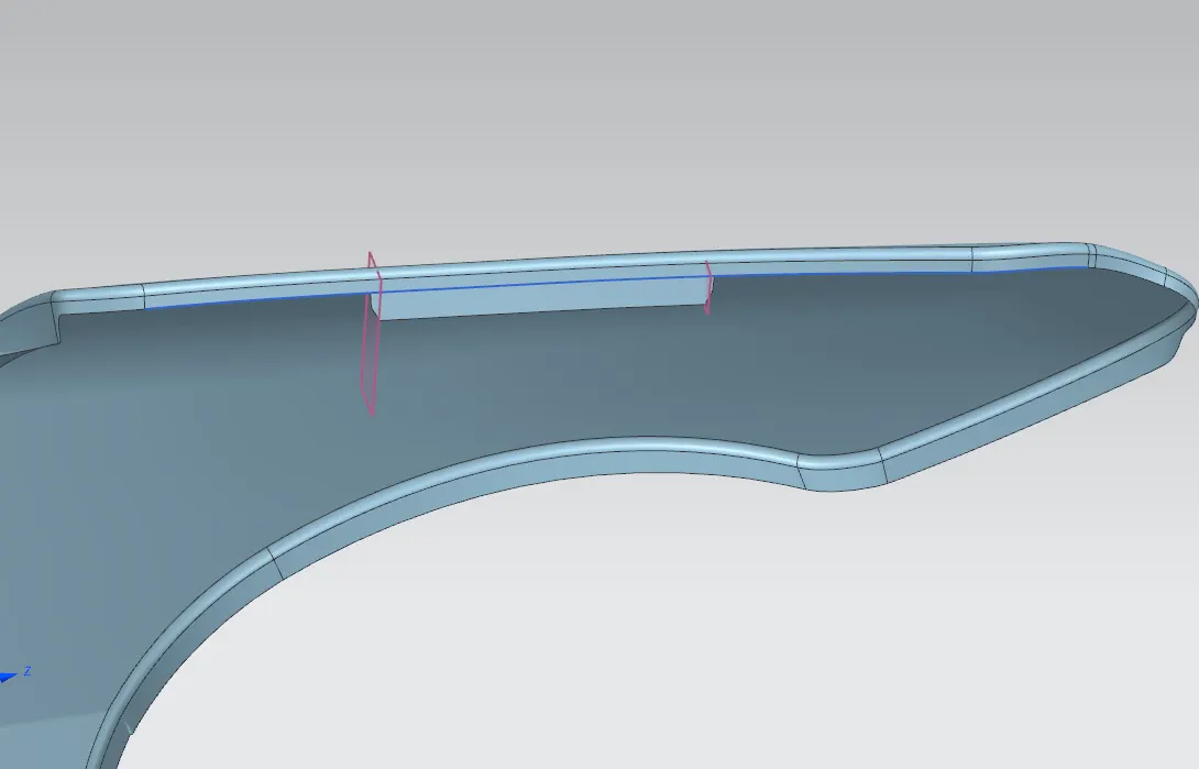
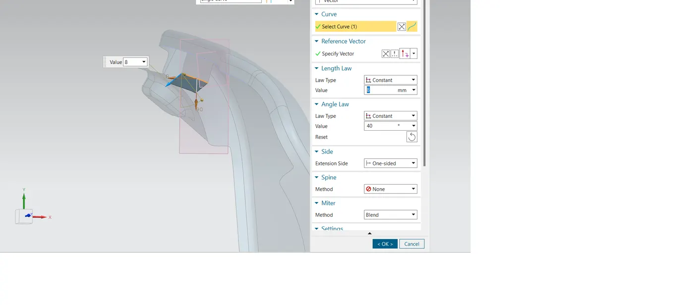
The given skin has the default top 3deg bend in the top which is given in certain angle for the Tool workability during assembly and fixing process.
Bottom of that created the flange for 8mm with an angle of 40deg it plays as a barrier .when a person see from the outside into the gap between hood and fender this flange will be visible instead of the engine compartment.
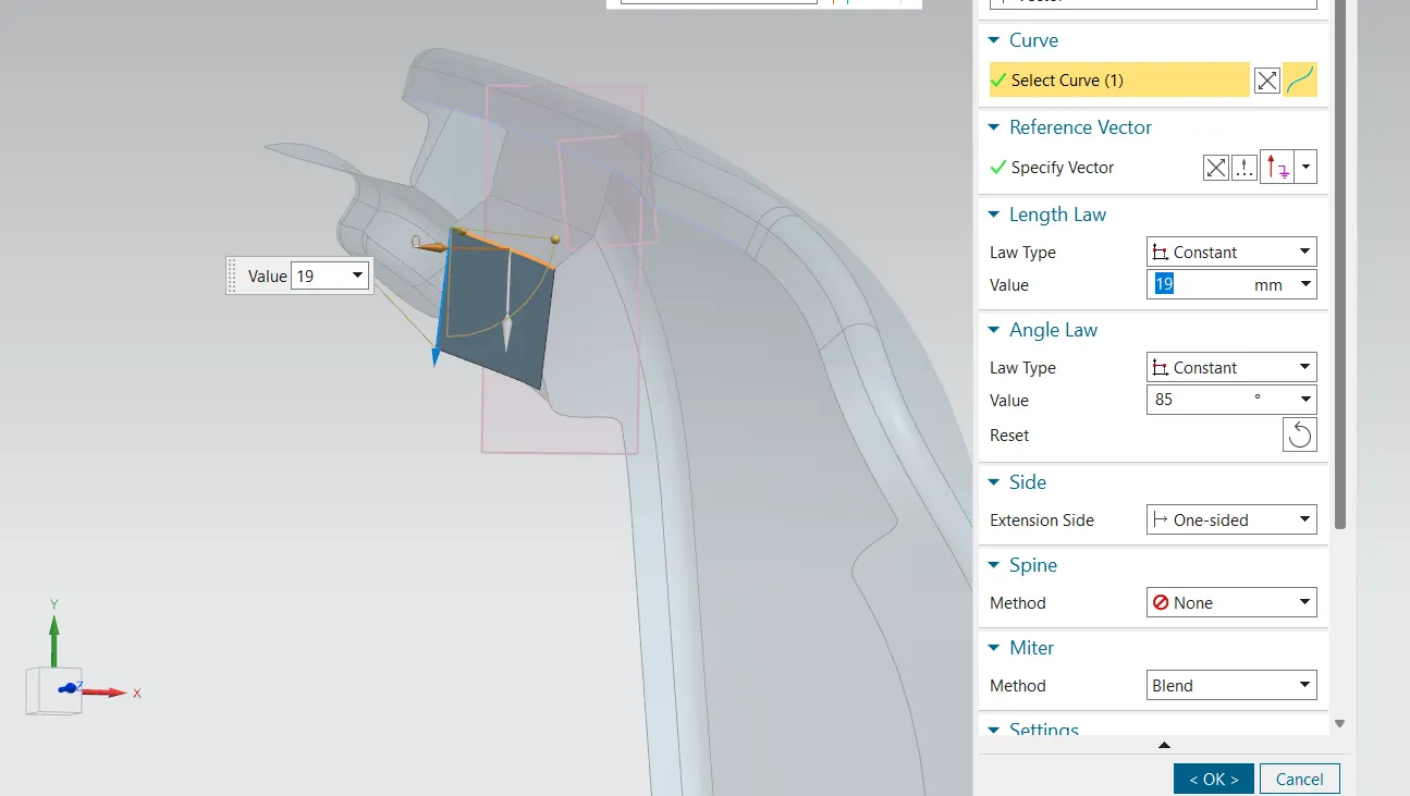
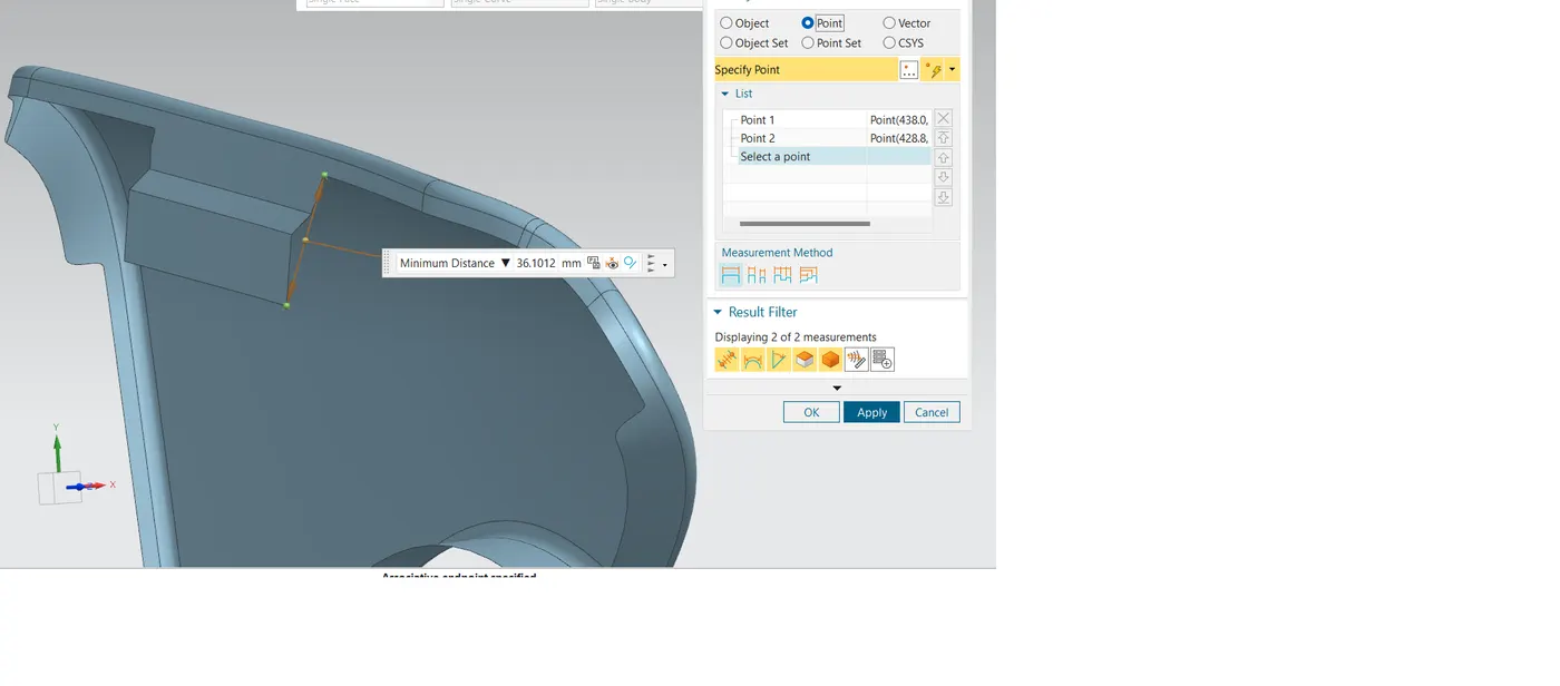
Created a 5deg law extension upto 19mm the height of the law extension should not exeed more than 40mm from the top if it increases then the spring back effect will occur after manfacturing it. To avoid that minimum value is maintained.
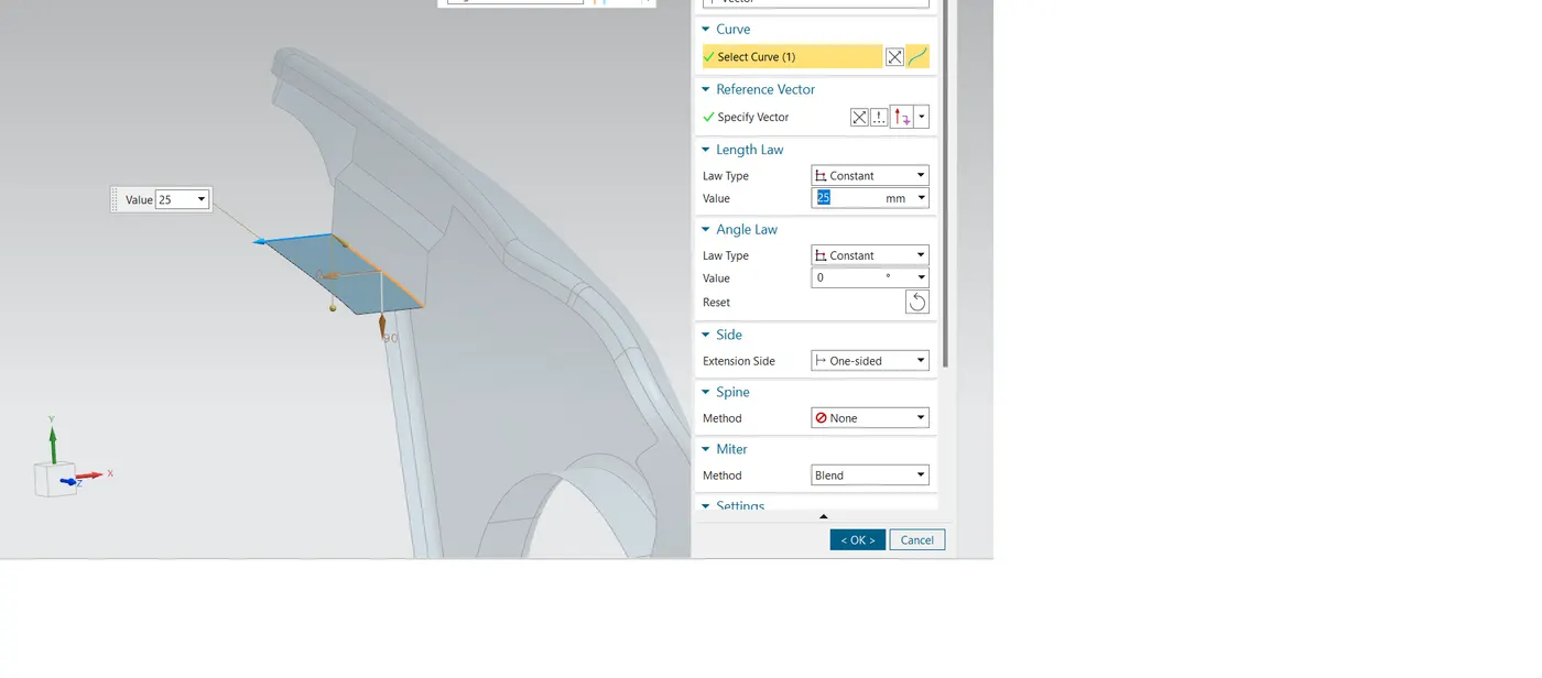
Created the flat law extension as per the mastersection. In this flat region the mounting embosses will be created.
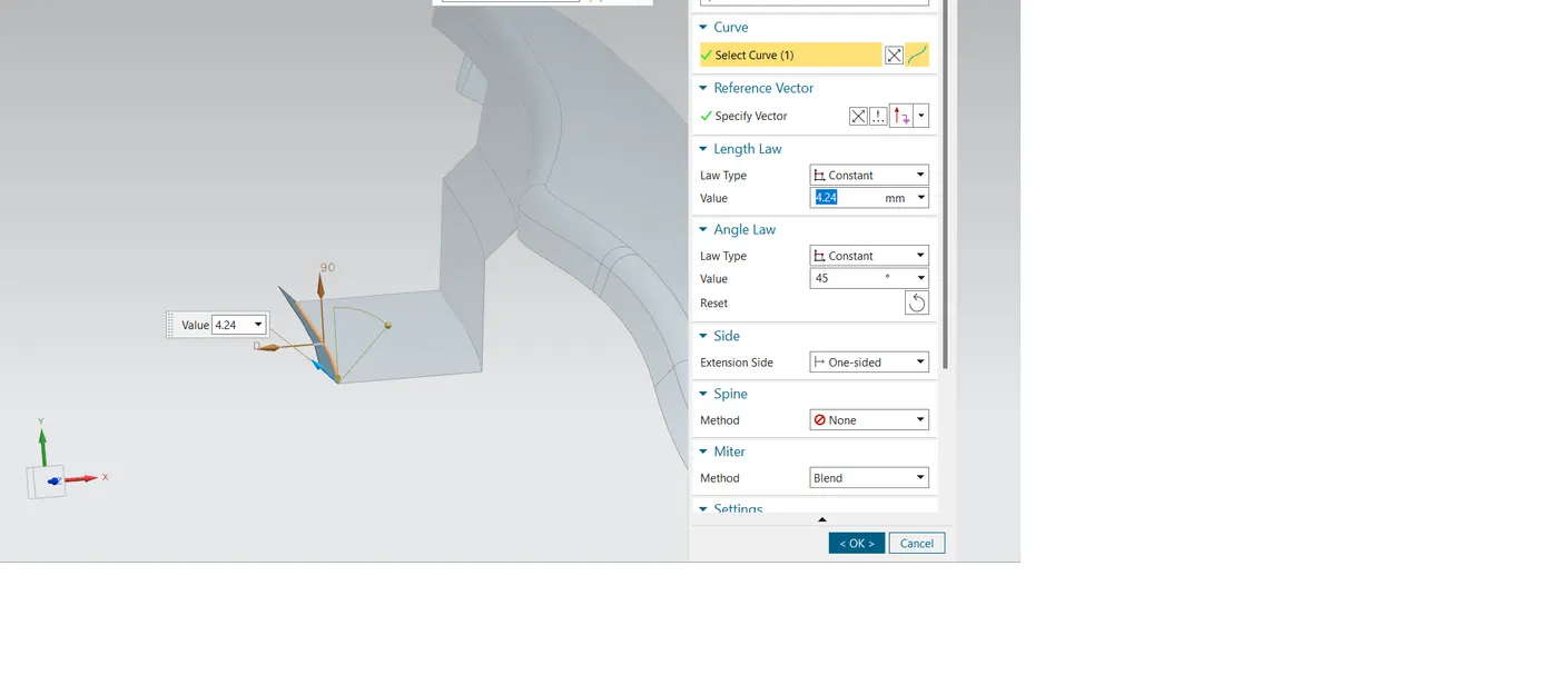
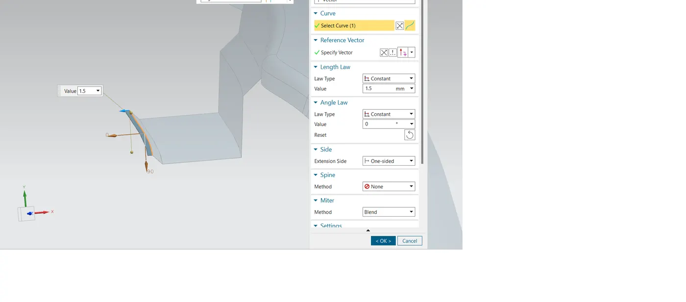
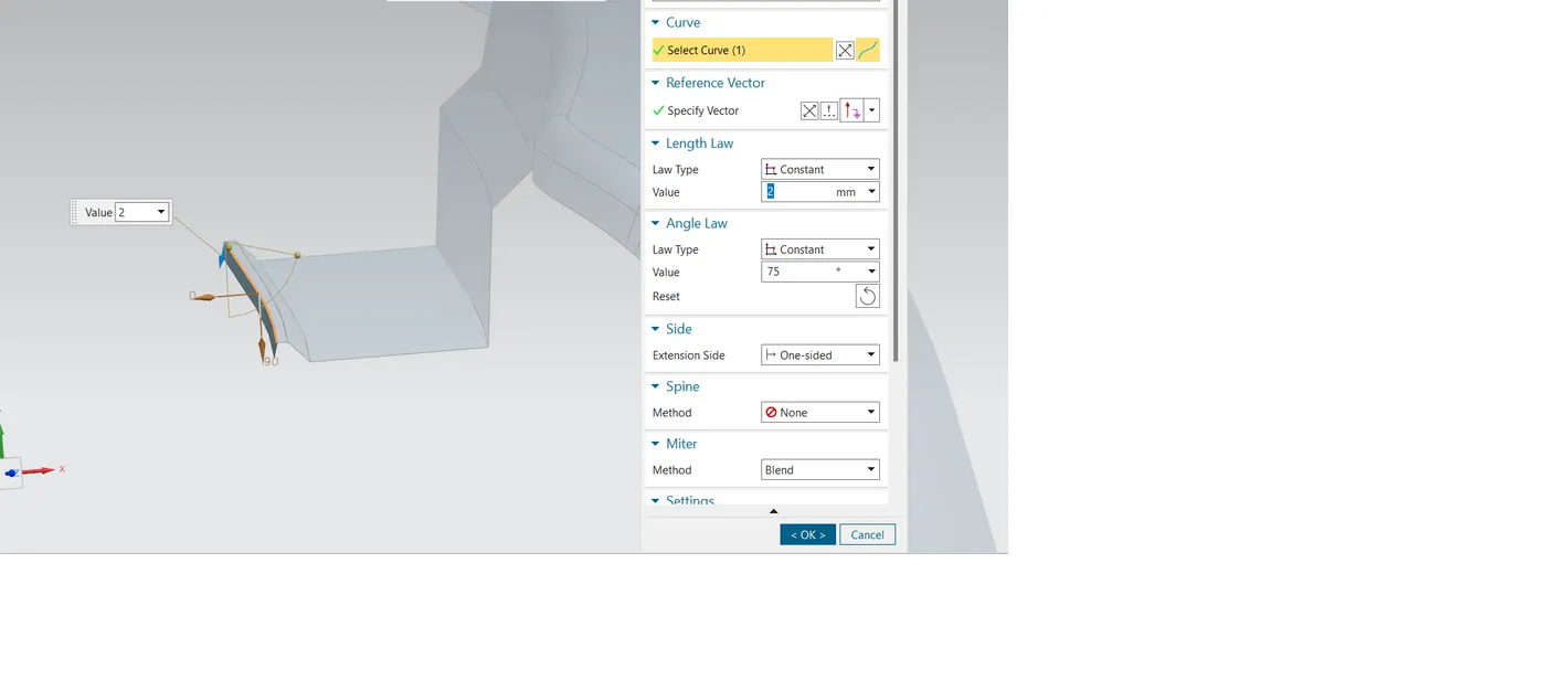
As per the mastersection created the bend in the end of the flat surface which will gives strength to the flat surface and the clearance from the edge of the bend to the engine compartment should be minimum 10mm and it will varies according to the industry standards.
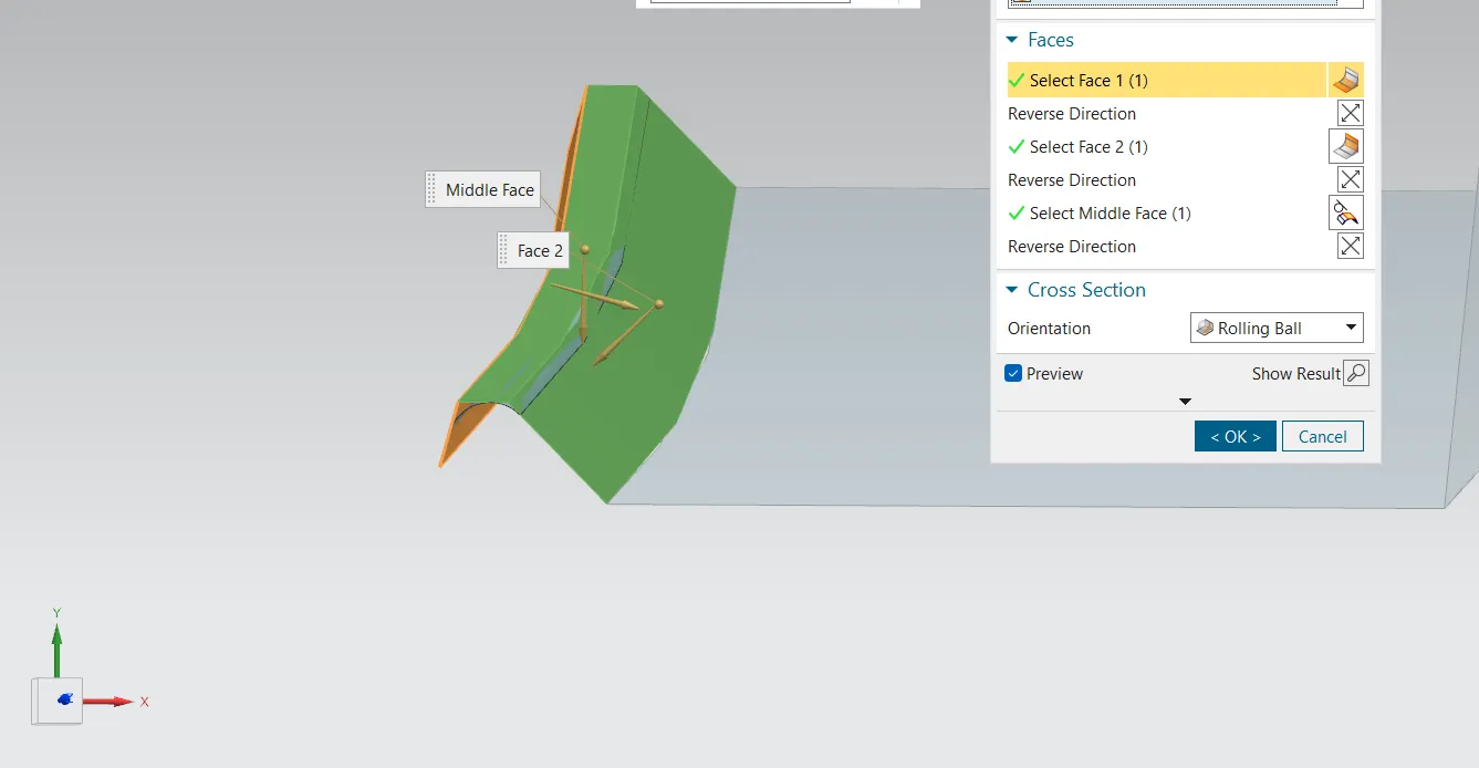
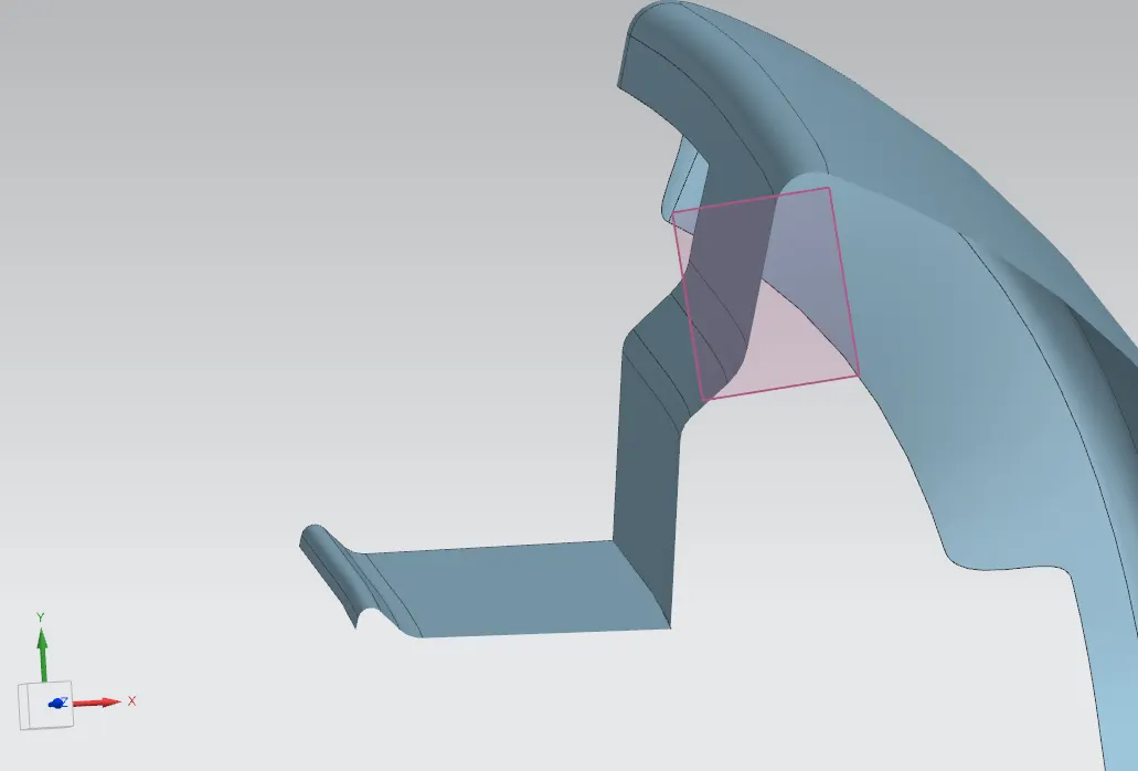
Given edge blends with respect to the mastersection.
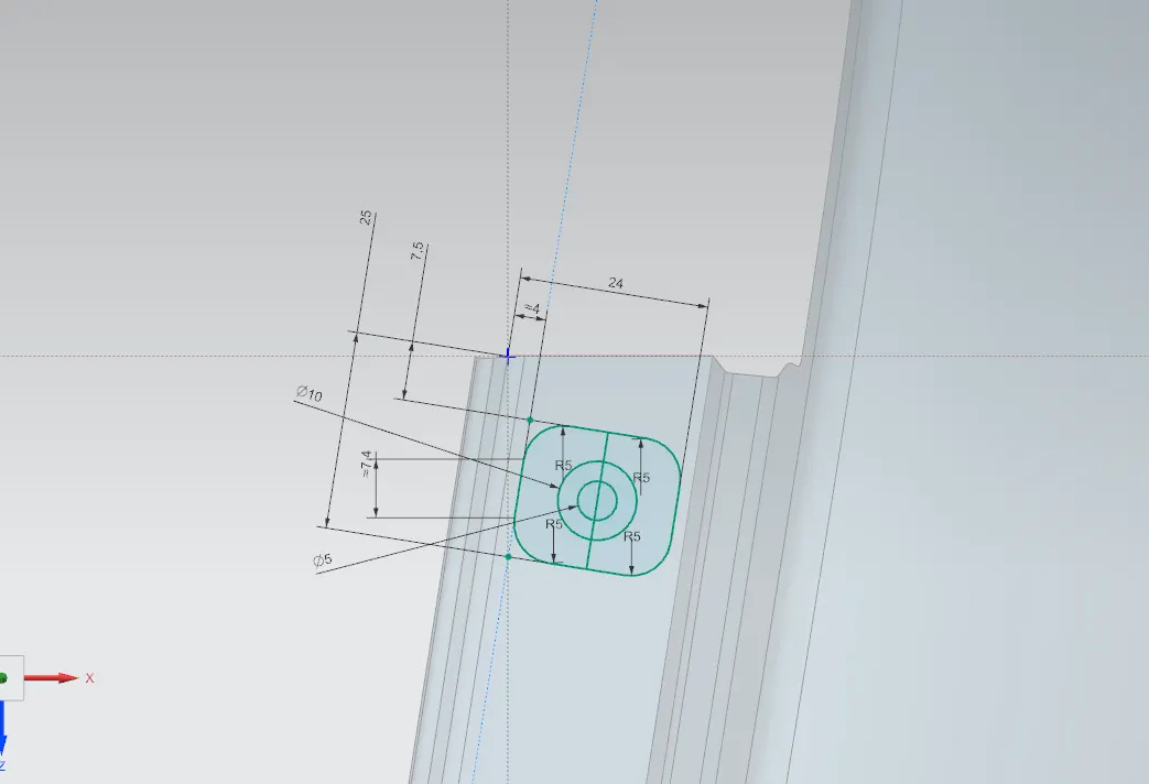
Created a fully defined sketch for the emboss in drip area.
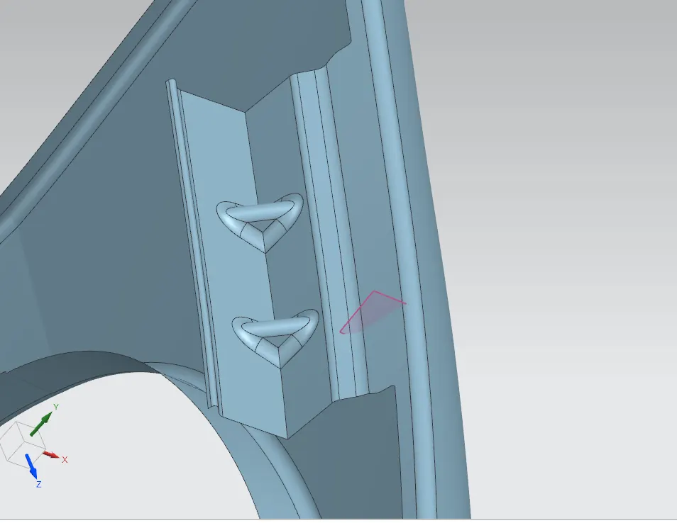
Created two ribs with the help of dart command, the ribs increase the strength in the drip area.
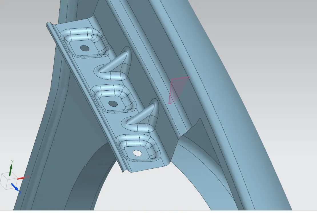
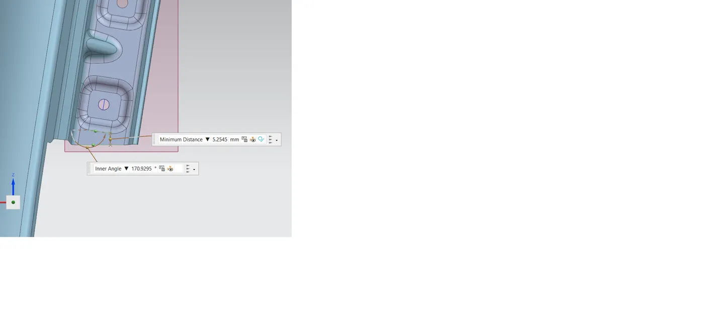
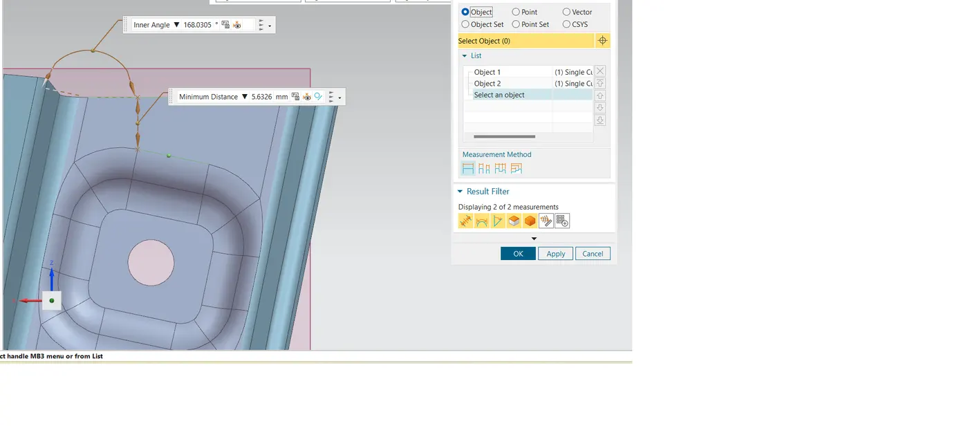
The three mountings were created in the drip area and embossed using a datum plane to make the lower surface of the emboss to be flat for mounting and the edge to edge gaps are maintanied in both the corners along Z direction. All the edge fillets for the emboss is maintained with the minimum fillet radius of 3mm+thickeness of the component(0.75mm)
Fender Wheel Arc area:-
Japan requirement
- The clearance of L of tire and fender measured in three different positions within the area K and produce clearance to validate the chart values.
- The clearance must be given 5mm greater in all the three postions.
- The value of should be more than 5mm at the line of 30deg front and 50deg rearend from the central axis of the wheel arch.
European requirement:-
Here the all the L value from different angles should be greater than 10mm with respect to the European standards.
Here they have taken -20deg to 200deg inbetween that taken more angles and from the top view the L should be 5mm from the outer most point of the tire from top view like shown in japan and european requirements which they are showing in side view & Top view .
These are the standards according to the road conditions and speed limits of different coutries.
First the lines will be drawn as per the requirements of the Japan/European/USA standard and the outer most edge of the fender arc and then the outer most face of the wheel must be measured. The projected points will be named as SA, SB, SC, SD, SE and then the values must be measured.Wheel arch claddings are there to stop water and dirt ingress from getting into tight spots around the wings of the car to prevent corrosion. They also protect any electrics or pipework from the water. It also prevents from throwing dirt and stones over the pedestrians.
Mountings for baffle region:-
This helps to keep the engine and other components cool, even in hot weather or under heavy use. The baffle also helps to protect the radiator from damage from dirt, mud, and other debris. The baffle also reduces the NVH of the fender.
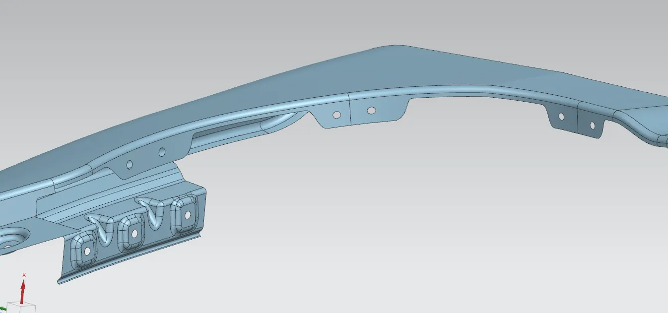
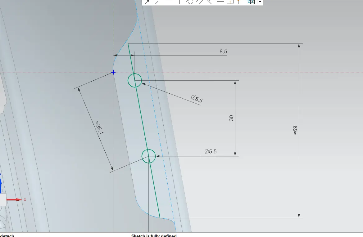
Using offset curve and curve on surface created baffle mounting cutouts. For the holes created fully defined sketches accordingly. The baffle is fixed with the pushpins mostly.
Sill Mounting:-
The sills of the car are part of the bodywork. The bodywork is the shell of the car and protects parts such as the engine from dirt and premature damage. The sill has a specific function, which is to protect and hide the bearing parts. The sills can be found under the doors, against the underside of the car.
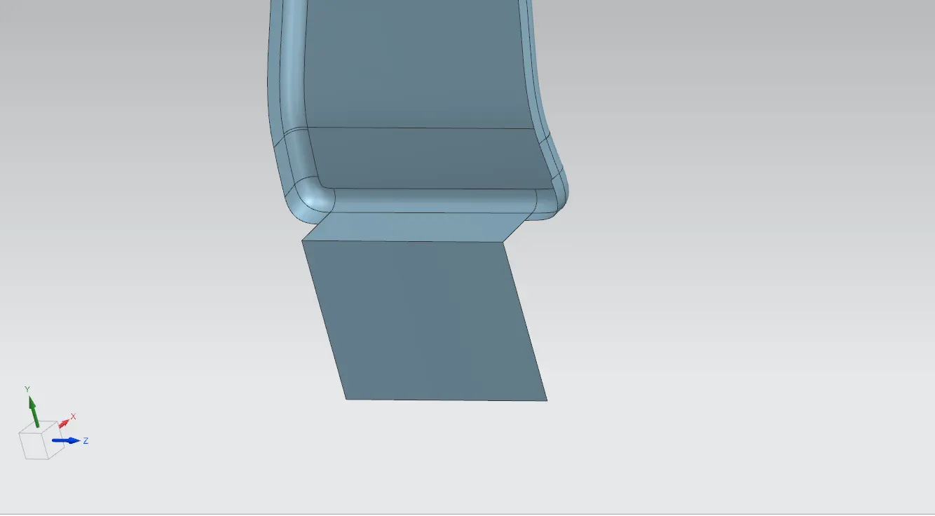
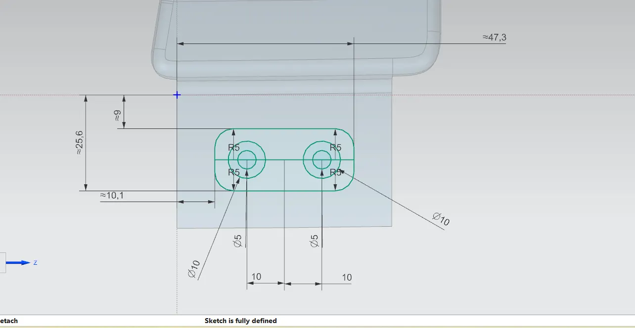
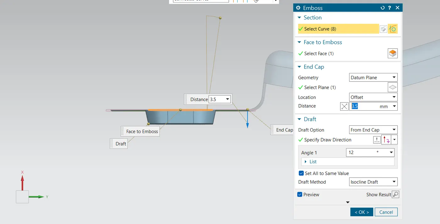
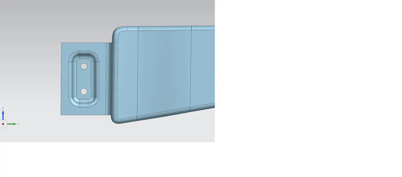
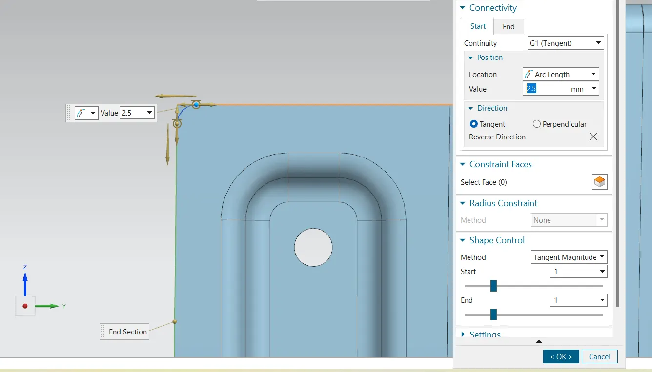
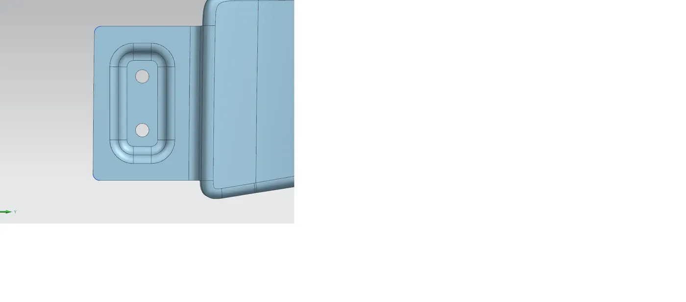
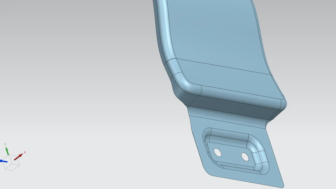
- Created the law extension for the sill mounting and created the sketch for the emboss and hole cutout.
- Created the datum plane using curves and points , after that embossed the sketch by projecting over the sill area.
- Given the fillet of 3+ the thickness of the component.
A pillar Mounting:-

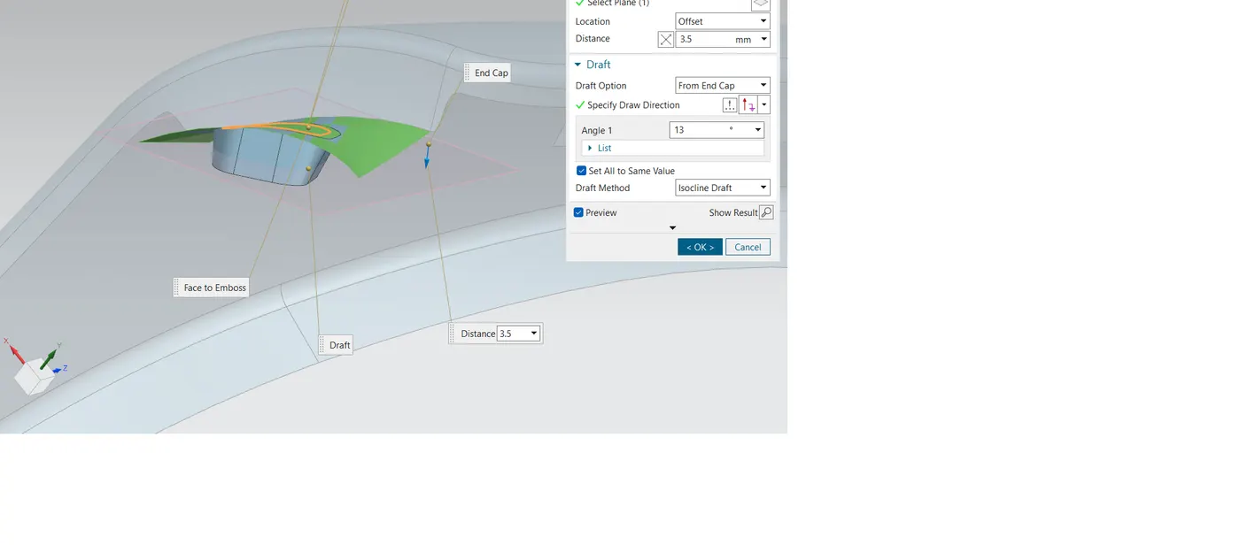
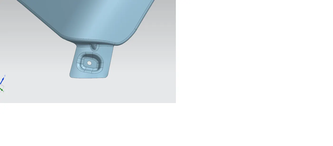
For taking the reference for the drip area cutout the A pillar mounting was already created upto law extension surface. After that created a sketch for the emboss creation along with that created a datum plane for flat base of the emboss and created a circle and trimmed in the emboss to create a hole. Rib created with the help of dart command. Edge fillets are given 3+ the thickness of the component and edge to edge clearance is maintained between 5-10mm.
Bumper Mounting:-
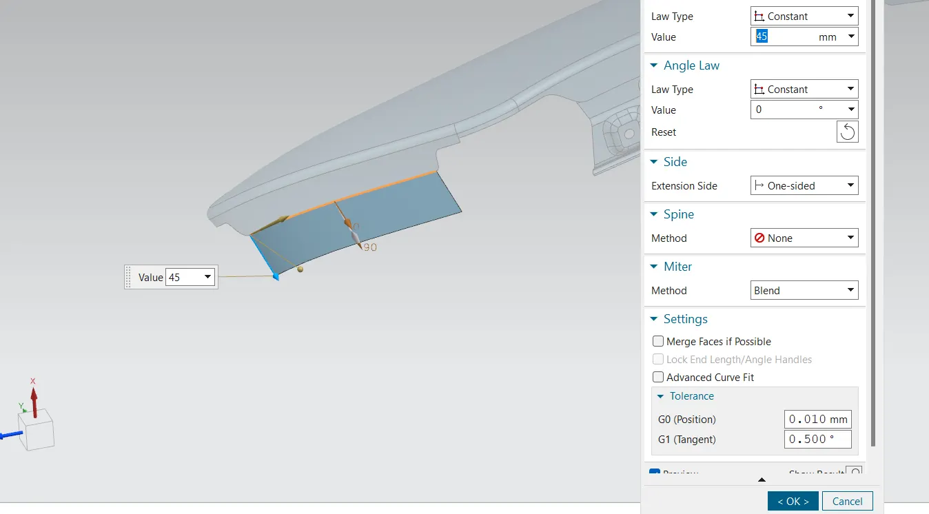
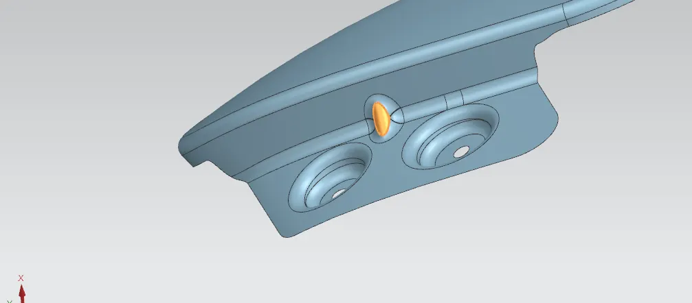
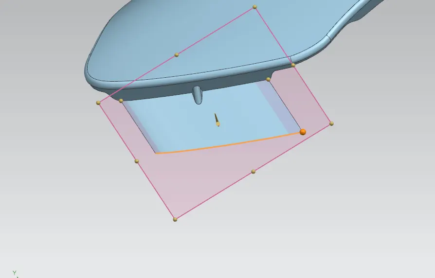
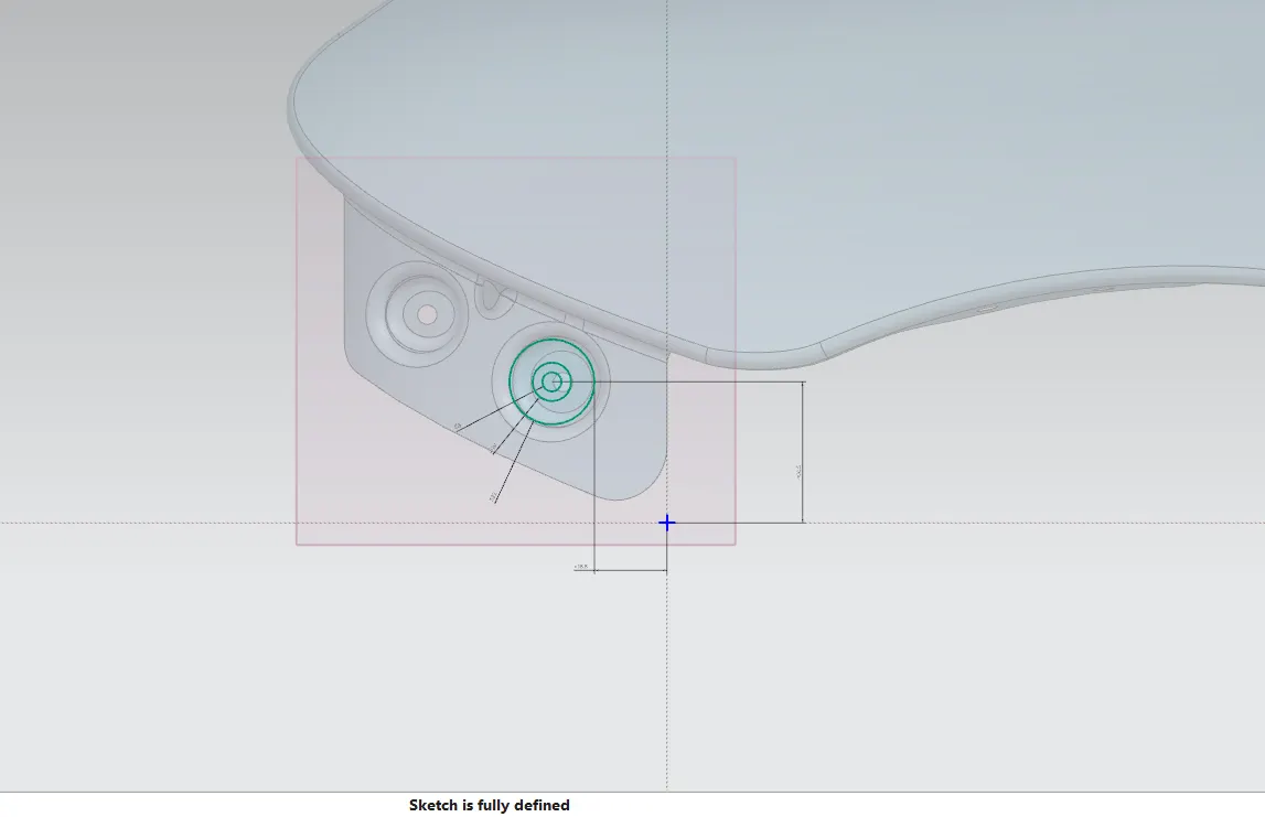
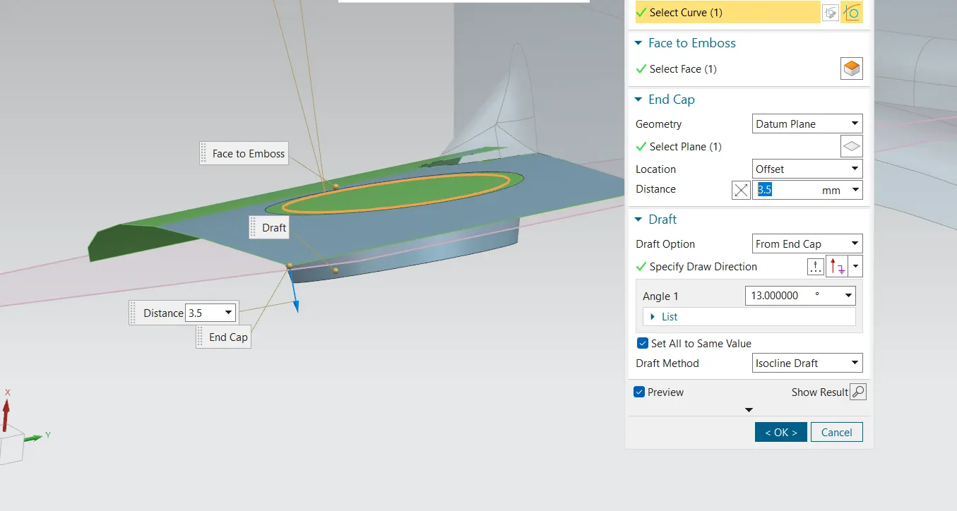
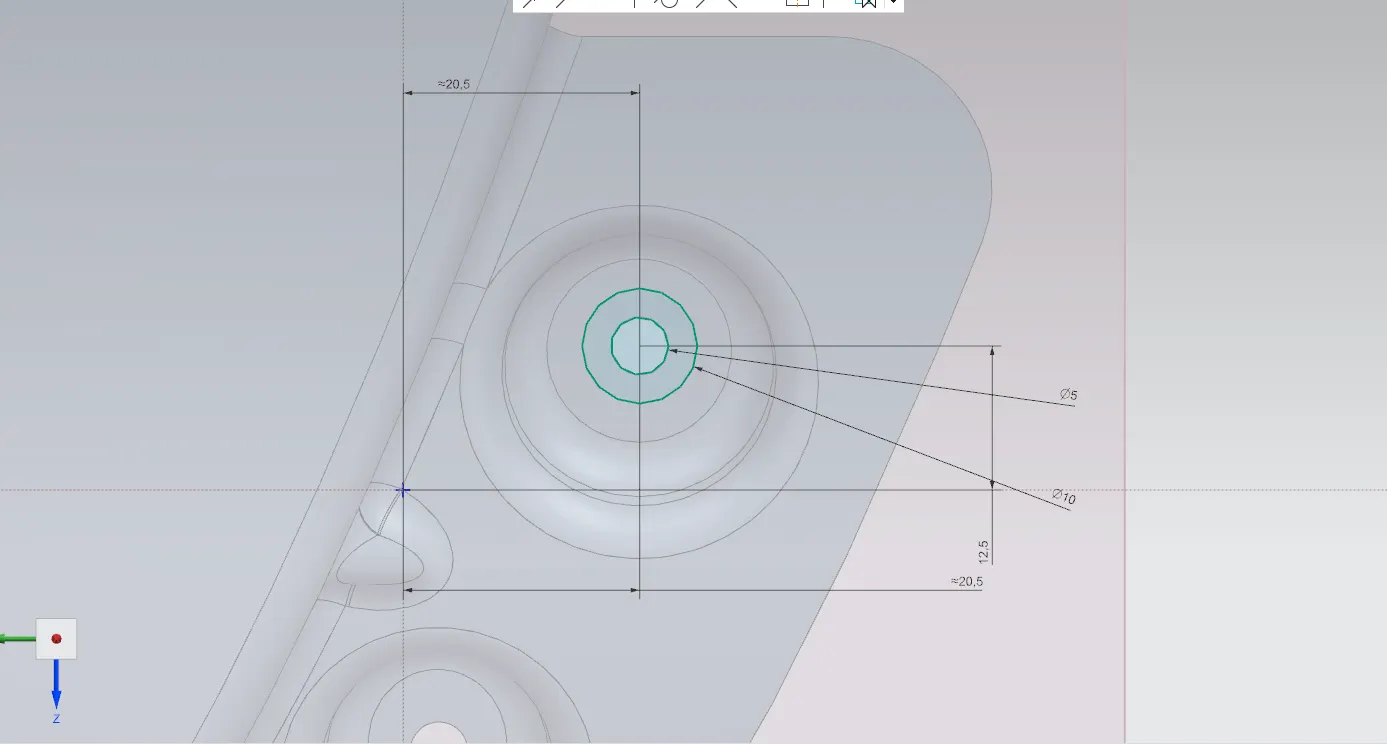
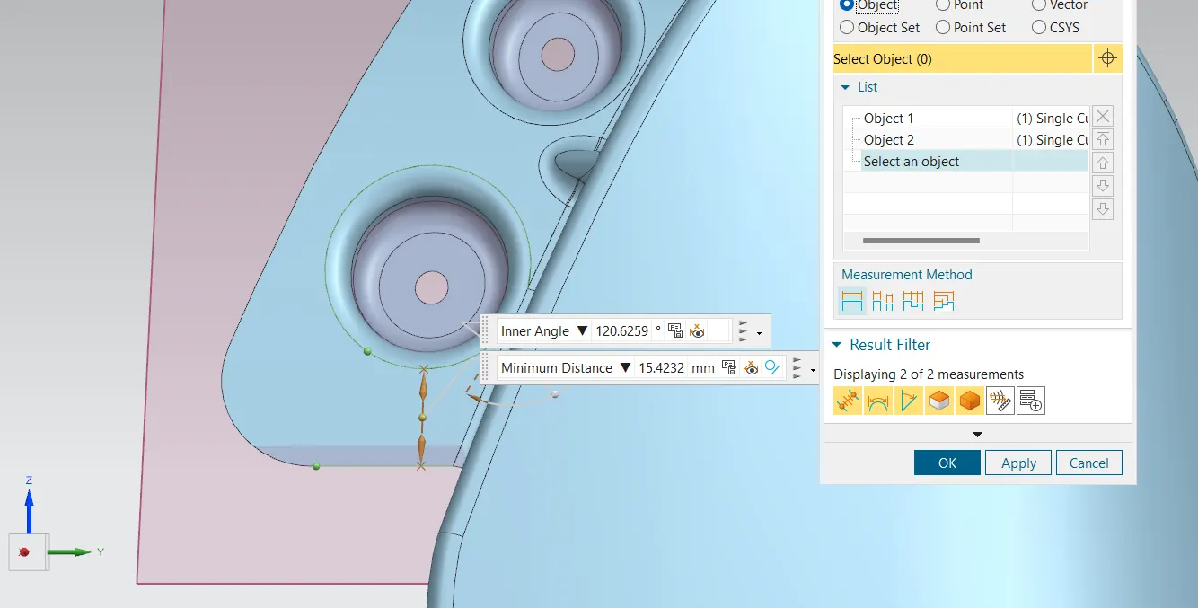
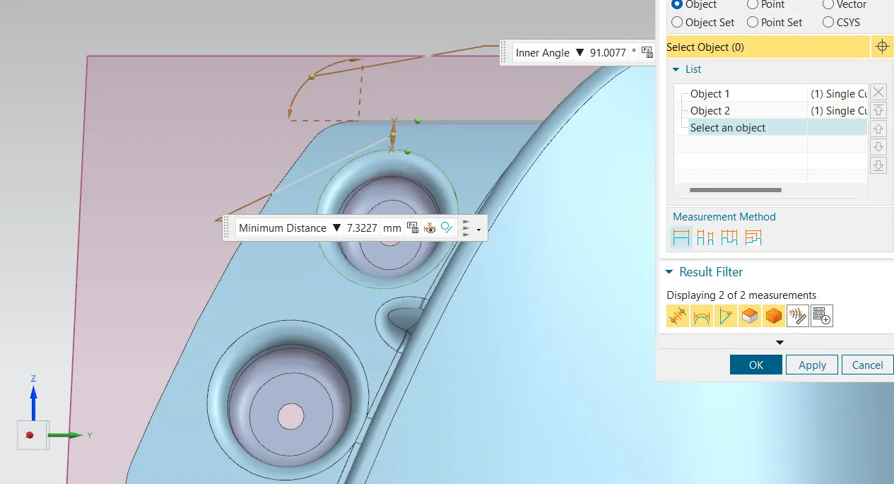
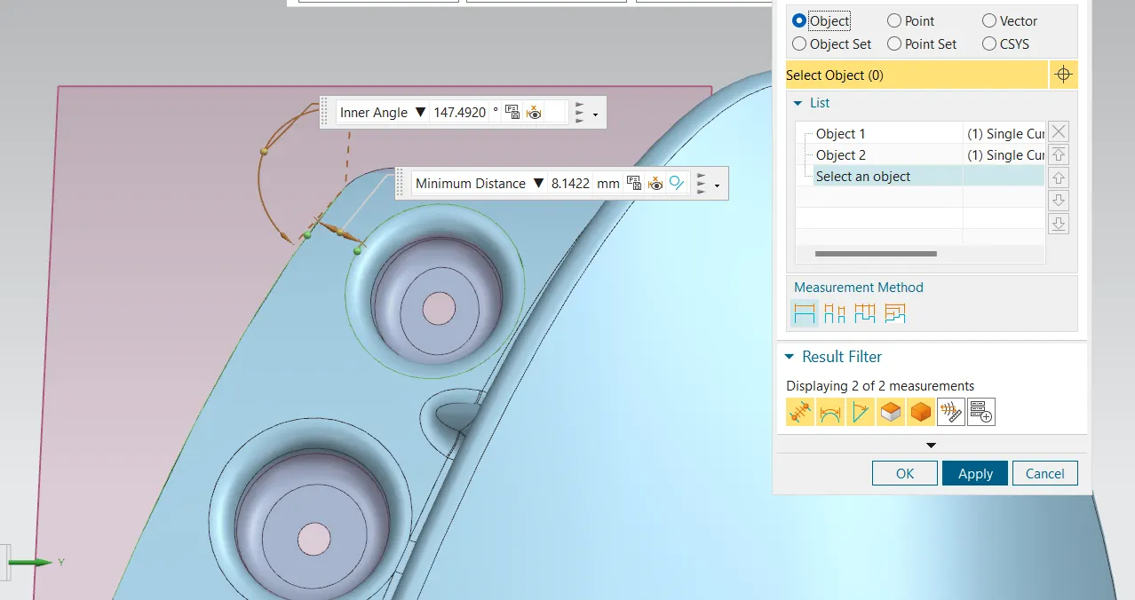
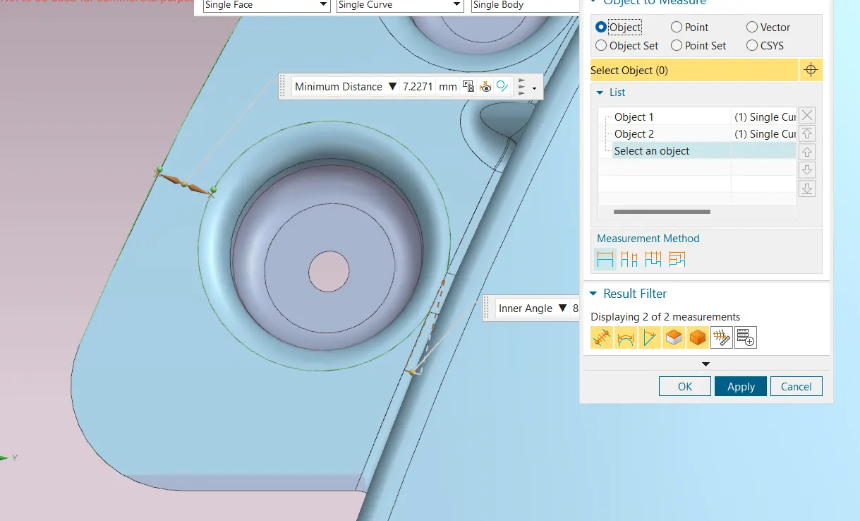
The law extension was created from the trimmed cut out of the fender skin and created a rib using dart command. After that, created a datum plane using three points from the law extension and created a circular emboss with a help of the sketch and the datum plane which made the circular mounting base as flat surface. Created two circular embosses for the mounting. All the edges were filleted with 3+ the thickness of the component. Edge to Edge clearance is maintained between 5-10mm along Z, Y direction .
Frontal crash regulations and requirement:-
For the frontal crash the WAD for the fender shall be 1700WAD (MIN 80 TO MAX 94MM) to meet the child and adult impact requirements. The above details in the image varies from car to car according to the industry.
Manufacturing methods :-
The Fender is mainly manufactured by the stamping process as same as hood , inserting the sheet metal and position over the die after the stamping process the required component achieve its shape.