Fender Design
FENDER DESIGN
Fender is the American English term for the part of an automobile, motorcycle or other vehicle body that frames a wheel well (the fender underside). Its primary purpose is to prevent sand, mud, rocks, liquids, and other road spray from being thrown into the air by the rotating tire. Fenders are typically rigid and can be damaged by contact with the road surface.
Sticky materials, such as mud, may adhere to the smooth outer tire surface, while smooth loose objects, such as stones, can become temporarily embedded in the tread grooves as the tire rolls over the ground. These materials can be ejected from the surface of the tire at high velocity as the tire imparts kinetic energy to the attached objects. For a vehicle moving forward, the top of the tire is rotating upward and forward, and can throw objects into the air at other vehicles or pedestrians in front of the vehicle.
When vehicle is moving, tires pickup stones and other things and hurt them in all directions. fenders are basically present to prevent any injuries to pedestrian and contain the motion of these particles. Most passenger automobiles have four fenders, one over each wheel with a narrow car body that exposes the tire, the fender is an exposed curve over the top of the tire. for wide body vehicles that cover the tire, the fender forms the wheel well surrounding the tire, and is not directly visible from the car body.
Wheel wells tends to be much larger than the diameter of the tire, because they donot move with the tire suspension and consequently must be large enough to allow the full range of the tire motion on the suspension without touching the interior of the wheel well. more elaborate designs include fender skirts for enclosing the outside edge of the wheel well, and stylised pontoon fenders for exposed fenders. Half bumber type fenders are more suitable because it reduces the material wastage
MOUNTING
- BODY
- A PILLAR
- SILL
- COWL
- DRIP AREA
CREATION OF FENDER
We had provided with a skin data of fender with outer edges extended.
for creating fender mouts we want to add various surfaces with help of Law extension.
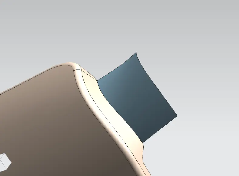
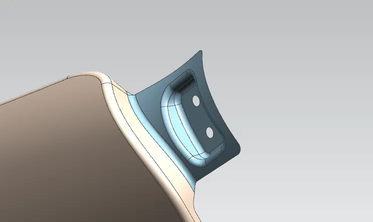
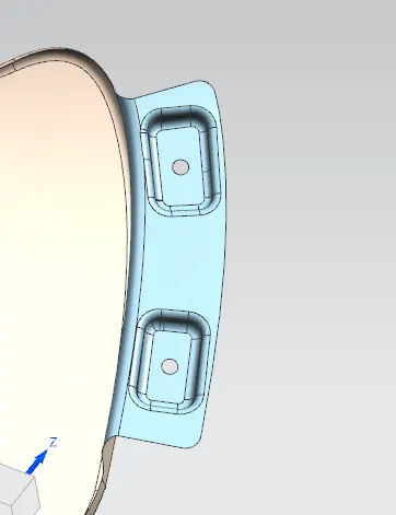
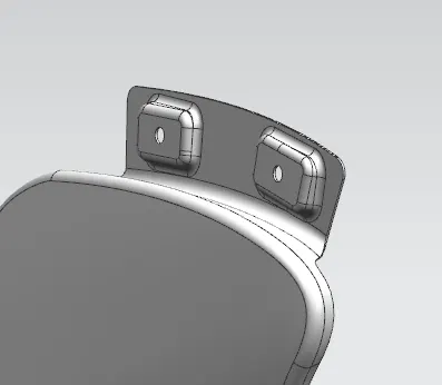
A PILLAR, BUMBER MOUNT
- offset curve in face the filleted corner end to 5mm
- then create a curve on surface selecting tha apillar connection face and create a spline using 3 points
- then trim of the excess regions
- then using law extension extend the edge of the sheet with an angle 90 degree to reuired distance.
- then if there is any irregular surface then cut of the irregular portion by creating a curve on the surface and trim sheet
- then make it more appealable and strong with the help of face blend
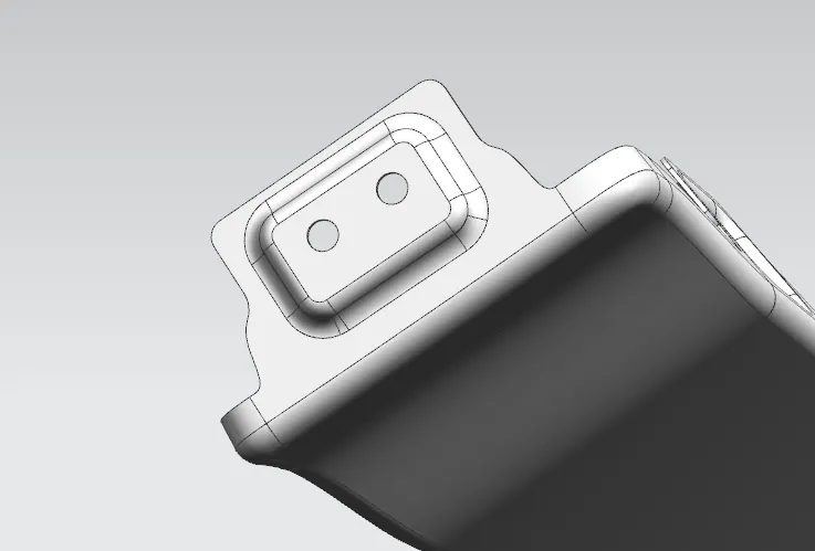
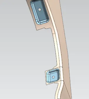
- then using 3 distinct points on the face of the extension create a plane and make a sketch for the mount
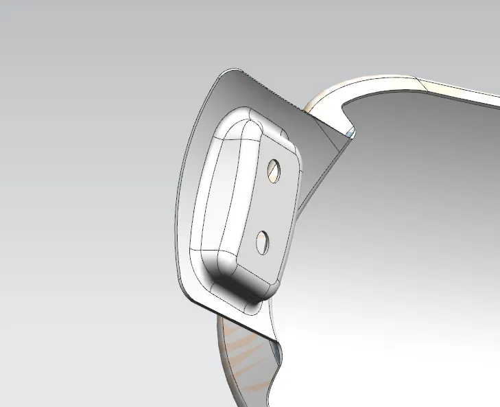
- create a 5mm circle in the middle followed by a 10mm circle as a reference for the relaxation area then around that circle with some free space given create a rectangular sketch and constrain all these drawings.
- then emboss the rectangle with 10 degree draft and required offset from the plane we created, the draft direction should be vertical direction because it will be the tooling direction
- trim off the circle we created from the sheet body and add blends to the sharp corners of the emboss.
A PILLAR
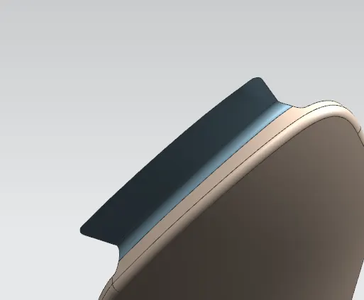
BUMBER
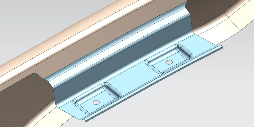
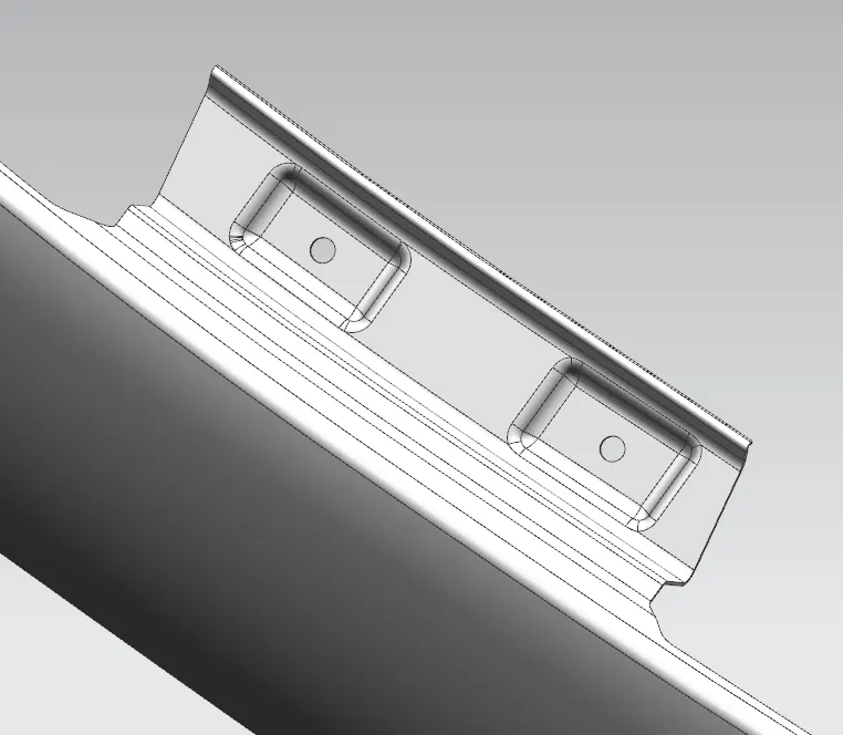
DRIP AREA
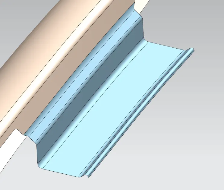
- for creating the drip area there was a master section given.
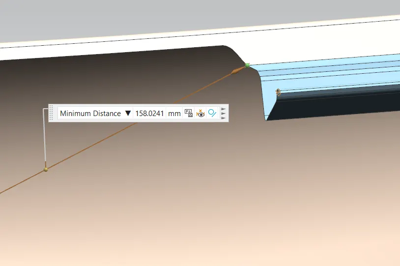
- for finding out the drip area dimensions create 2 planes with the help of offset curve on face, datum plane (using on curve, arc length) then next datum plane with reference of the above created datum plane and the measuring point then add offset value of 150mm
- then intersect the sheet with respect to the planes we created then add curve on surface then trim of the excess area
- the curve on surface is added for adding more stability and reducing tooling failure
- then with the help of law extension create the respective surfaces with the angle and length given.
- add blends to the sharp corners according to the master section.
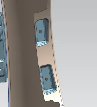
- for mounting create 2 rectangles with same procedure we done for A pillar.
- add blends for stability
SPLASH / BAFFLE AND SILL MOUNT
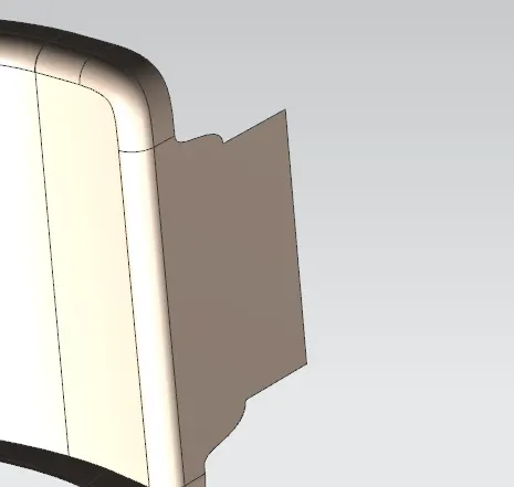
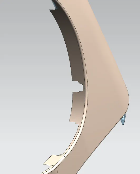
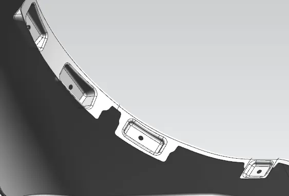
- for creation of sill mount it is little bit different from the a pillar and bumber
- for sill we want to extend the given sheet to 30mm or your required distance
- then cutt off the sharp corners using trim sheet and boundaries as bridge curve we created
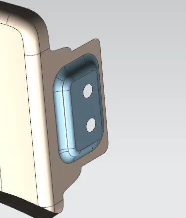
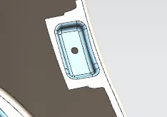
- then create the mountings same as A pillar
- then after thicken where all we extended the sheets add edge fillet to avoid tooling failure
SILL
SPLASH
MANUFACTURING PROCESS
The manufacturing process includes the following steps that firstly, unfolding and shearing are carried out on a plate, wherein a proper cold roll specification is selected at first, a cold roll is unfolded, and then the unfolded cold roll is sheared to an iron plate of the corresponding size according to production material specifications; secondly, oil pressing and punching are carried out, wherein the iron plate is extended at first, then side shearing and punching are conducted on the iron plate, folding and shaping are carried out on the iron plate, and finally reshaping is carried out on the iron plate; thirdly, small first parts of the fender are machined, wherein first of all, the iron plate is punched to a needed outer contour blank, then the iron plate completing the outer contour blank is further shaped, and the iron plate is punched at last; fourthly, installation and welding of a metal plate are conducted. The manufacturing process for the car fender is simple and high in production efficiency; a body of the fender and the small parts can be separately machined, so waiting time is shortened; working efficiency of production is improved.
Tandem press, Transfer press are manufacturing technicalities
Quenching is used for adding strength to the part, Quenching can be done with the help of pouring water, cooling chamber, ice chamber, air
TANDEM PRESS
Tandem press is a specialized manufacturing process used in sheet metal work. It involves the simultaneous operation of two or more presses arranged in tandem, meaning one after the other in a sequential manner. This process is particularly useful for forming complex sheet metal parts that require multiple stages of shaping and manipulation.
In tandem press operations, the sheet metal undergoes a series of forming, bending, and cutting operations as it moves through the presses. Each press in the tandem setup performs a specific task, and the combination of these operations allows for the creation of intricate and precisely shaped components.
TRANSFER PRESS
A transfer press is a specialized type of mechanical press used in metalworking and manufacturing processes, particularly for producing large quantities of stamped or formed metal parts. Unlike a standard single-station press, a transfer press involves a coordinated system of multiple stations, or "dies," which perform various operations on the metal sheet as it moves through the press. This type of press is commonly used for producing complex and high-volume components.