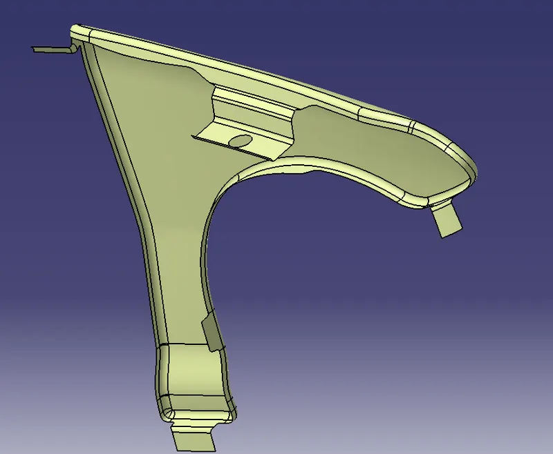
Fender Design
AIM
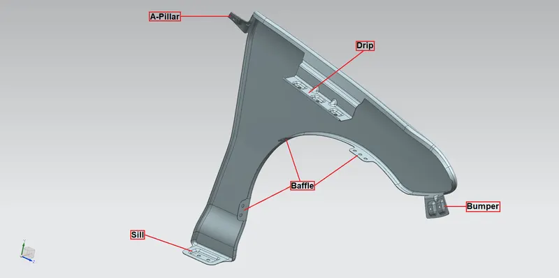
Follow the given master section to create the Drip Area. For the Sill, Bumper, Baffle(Splash), and A-Pillar mount create your design according to the Engineering standard you learned. Prepare a report with the relevant images included for the mounting points made.
WORKBENCHES USED
Geometric Shape Design and Sketcher
PROCEDURE
- Creation of Parallel Curves along the faces of the Fender
Create a parallel curve along the side faces of the fender at a distance of 5mm. Create lines between two points where parallel curve or in case of errors.
- Creation of Curves of Gaps for Sill, Bumper, Baffle, and A-Pillar
Create points on the parallel curve at a specific distance between them and then create the other two at the outermost edge of the fender at a distance lesser than the previous two points. Provide a split along the curve with a point as the cutting element. -----Use Connect Curve for connecting the points adjacent along the faces. Extrude a portion along the drip area and provide a split along the parallel curve with the fender as the cutting element-----. So we get a split all along the entire fender. Do the same for the Sill, Bumper, Baffle, and A-Pillar. Better use the join operation and then use Split along the surface with the curve as the cutting element.
- Creation of Drip, Sill, Bumper, Baffle, and A-Pillar
Create a Sweep along the A-Pillar in the right direction with the draft direction along the Z axis with angle value 0 and length 1 as 50mm. Join the main surface to the sweep and then provide an edge fillet with a radius of 3.75mm.
Create a sweep along the Drip with X direction, Length 1 as 10mm, and angle 40 on the left bottom direction. Create another sweep along X direction, 50-degree angle, 5mm length 1, left top direction. Use Join and Edge fillet operation between the swept parts.
Create a sweep along the Bumper with an X-axis, Angle 75degree, Length 1 as 26mm, left bottom direction. Use join and edge fillet operations.
Create a sweep along the Sill with a Y axis, Angle 0, Length 1 as 20mm, Bottom direction. Use join and edge fillet operations.
Create a sweep along the Baffle with a Y axis, Angle of 90 degrees, Length 1 as 7mm, and Right Direction. Use join and edge fillet operation.
- Creation of a hole in the Drip Area
Define the plane along three points on the 3rd sweep surface. Create a hole in it using a sketch workbench. Extract the swept surface. Project the circle onto the extracted surface. Join the entire surface to the extract and apply split along the join with the circle as the cutting element.