Fender Design
OBJECTIVE:
Design a front fender from the given skin data and the master section provided with Drip mounting, A-pillar, Sill, Bumper, C mounting and Splash mountings.
INTRODUCTION:
Fender is the US English term for the part of an automobile (vehicle body) that frames a wheel well (the fender side). Its primary purpose is to prevent sand, mud, rocks, liquids and other road spray from being thrown into the air by the rotating tire.
When the vehicle is moving, tires picup stones and others and hurl them in all directions. Fenders are basically present to prevent injuries to pedestrians and constrain the motion of these particles.
Most passenger automobiles have four fenders, one over each wheel. For Vehicles with a narrow car body that exposes the tire, the fender is an exposed curve over the top of the tire. For wide body vehicles that cover the tire, the fender forms the wheel well surrounding the tire and is not directly visible from above the car body.
TYPES OF FENDERS:
Classified based upon the area covered.
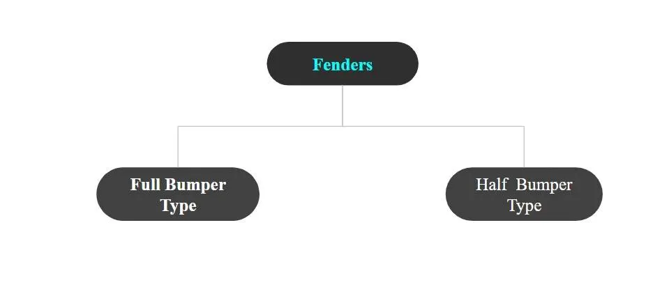
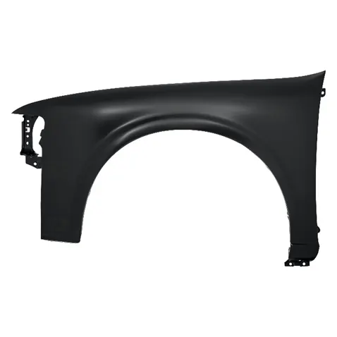
1. Full Bumper Type:
Full Bumper type is traditional type of fender where more material consumption is observed. This type is used in old design of automobiles where it increases the overall weight and thus reduces performance. The maintenance also relatively more due to more surface.
2. Half Bumper Type:
Half Bumper type is modern design where less material consumption is observed. So productivity increses by reducing size of blank and thus providing more performance. The maintenance also relatively low compared to full bumper type.
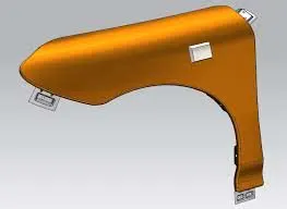

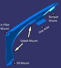
MOUNTINGS OF FENDER:
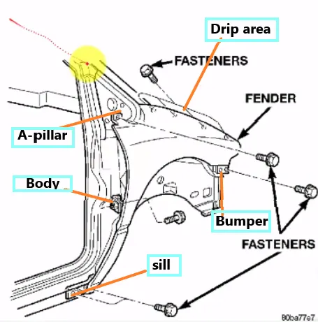
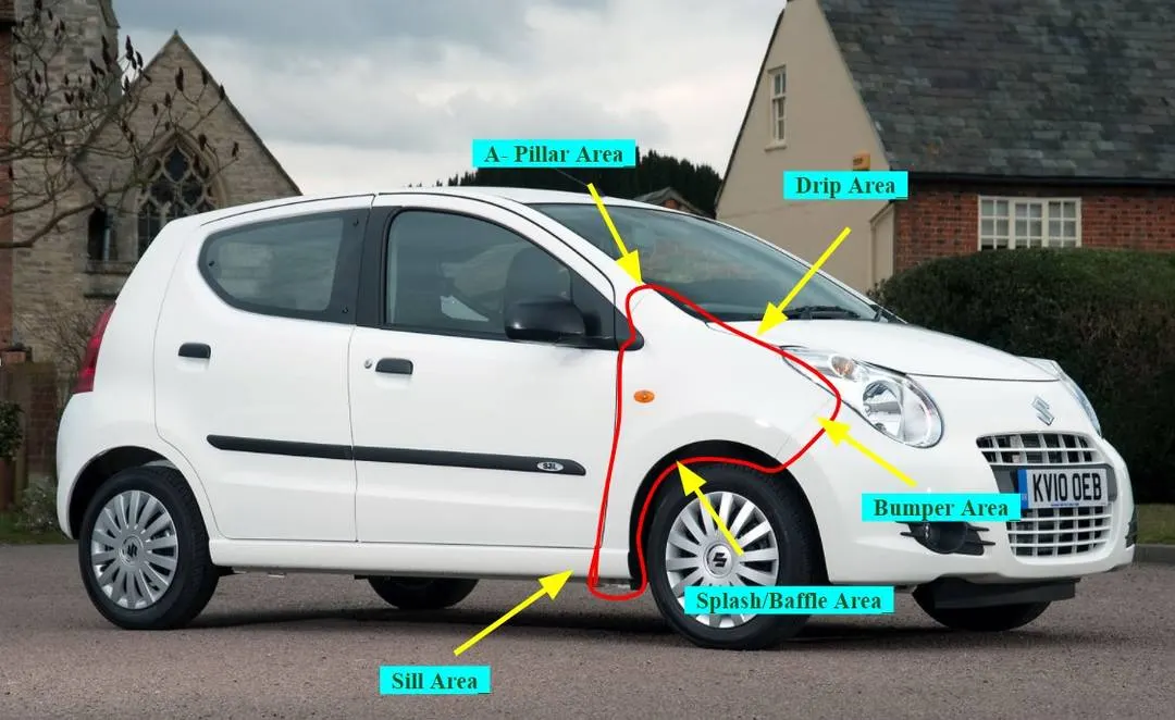
Inorder to fix the Fender, mountings were essential. In our design we classified these mountings in 5 areas, namely..
- Drip mountings area
- Sill mountings area
- Bumper mountings area
- A - Pillar mountings area
- Splash/Baffle mountings area
FUNTIONS OF FENDER:
- Car fender limits the exposure of your body and engine to external elements that are harmful.
- It provides safety to the driver and passengers at the time of accidents or collisions. They are manufactured in a way to provide bend during front and side collisions.
- Fenders flares are attached to eensure that both the body and engine have minimal contact with corrosive elements.
- It helps to avoid wind resistance and make your car more aerodynamic.
DESIGNING OF FENDER MOUNTINGS & It's CONSIDERATIONS:
Design or Import the Fender Skin data for designing mountings over it.
1. DRIP MOUNTINGS:
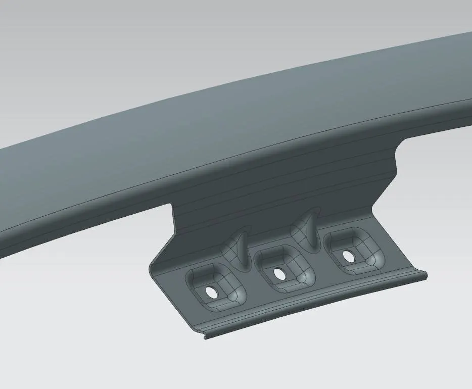
Firstly, the basic design of a fender involves in developing the drip area as it is a major mounting region and requires certain considerations to meet the standard values. This design takes a vital role for maintaing proper gap between hood and the fender which shouldn't be visible for human eye.
PROCEDURE:
- Import the skin data from parent file.
- Identify the A Pillar mounting area which later took as reference for drip location.
- Once identified, Offset the face and draw some splines using curve on surface Trim off the extra surfaces.
- Now create a datum plane section SC -SC at distance of 150mm as per above data.
- Use A pillar outer most edge as reference and create one more datum section SA - SA at a distance of 300 or less as per above data.
- Now use intersection curve to a create a curve between two set of objects using datum plane and fender face (for drip area).
- Repeat the same step for other datum as well.
- Offest the face at 5mm and draw splines at various identified places for various mountings using curve on surface. Trim off the the extra portion.
- Now extend the sheets using law extension as per given standard data(above dia.) and apply fillets using face blends.
- Once drip area is created for mountings, create embosses using Emboss command by drawing few sketches on parallel plane and projecting on it.
- Create holes in emboss with the help of sketches and trim sheet. Apply fillets using face blends
- Gussets/Darts can be given at the joints after sewing before blending the face to strengthen the component.
2. BAFFLE/SPLASH MOUNTINGS:
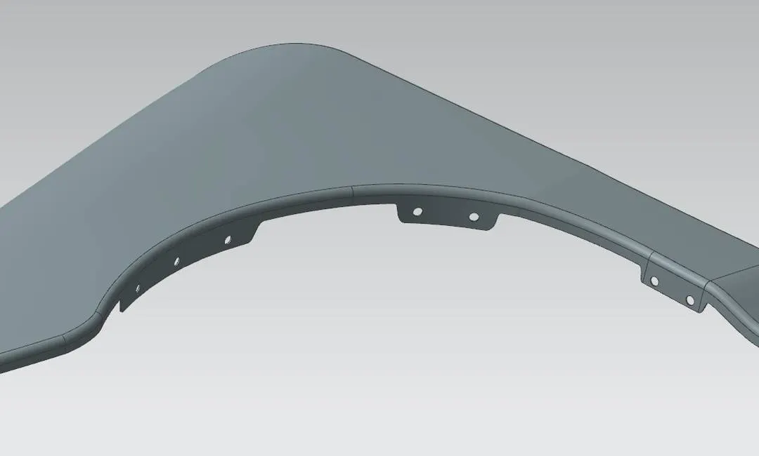
In order to stop all the debris entering into the engine room and other components splash protector mountings is been introduced. It just reqiure a area to hold the splash protector, so holes or slots are provided as per requirement.
PROCEDURE:
- Using previous drawn offset curve on face, draw few splines as per requirement with the help of curve on surface command.
- Now trim off the extra portion or surface which is not required.
- For Holes Creation - Create Datum planes on the particular face or draw a sketch on parallel datum plane and project it. Trim off the portion by selecting proper faces and sketches in target and boundary option.
- Similary repeat the steps for creating holes/slots on other faces.
- Make sure that no sharp edges were left over which will later create problem while thickening. If found give some reliefs using bridge curves/curve on surface and trim it off.
- Blend the created embosses and joints using face blend.
3. SILL MOUNTINGS:
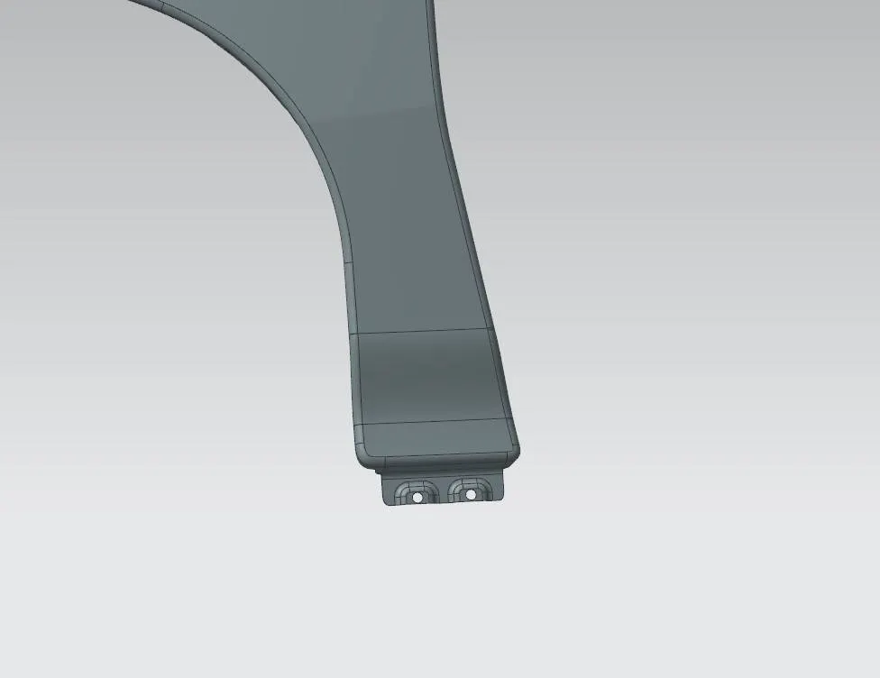
An automobile vehicle is necessarily with wide openings for accommodating doors at both sidesof its body. Since the vehicle body suffersfrom various kinds of externally derived forces such as vertical bends and longitudinal twists which act around the axis of the vehicle body, a prerequisite is that those portions of the vehicle body which surround the door openings, especially the lower portion, be provided with sufficient rigidity. This prerequisite is generally met by using side sills which are individually located at a lower right and a lower left portion of a vehicle body in such a manner as to extend in the longitudinal direction of the vehicle body. The side sills which serve as reinforcing members for insuring the rigidity of the vehicle body around the door openings.
PROCEDURE:
- Extend the sheet using Law extension.
- Draw few splines as per requirement with the help of curve on surface command.
- Now trim off the extra portion or surface which is not required.
- For Emboss Creation - Create Datum planes on the particular face or draw a sketch on parallel datum plane and project it. Use Emboss command, select the curves and datum plane in end cap portion to create emboss.
- For Hole Creation - Draw circles on previous sketch, trim off the portion by selecting proper faces & sketches in target and boundary option.
- Make sure that no sharp edges were left over which will later create problem while thickening. If found give some reliefs using bridge curves/curve on surface and trim it off.
- Blend the created embosses and joints using face blend.
4. BUMPER MOUNTINGS:
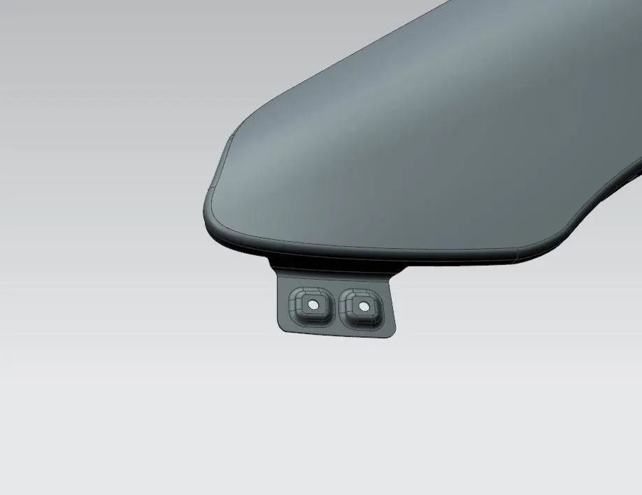
Bumper is a structure attached to or integrated with the front front and rear ends of an automobile to absorb impact in collision, ideally minimizing repair costs. They are increasingly being designed to mitigate injury to pedestrians struck by cars, such as through the use of bumper covers made of flexible materials. Front bumpers especially have been lowered and made of softer materials, such as foams, crushable plastics to reduce the severity of impact on legs.
PROCEDURE:
Similar to that of design of Spill mountings.
- Extend the sheet using Law extension.
- Draw few splines as per requirement with the help of curve on surface command.
- Now trim off the extra portion or surface which is not required.
- For Emboss Creation - Create Datum planes on the particular face or draw a sketch on parallel datum plane and project it. Use Emboss command, select the curves and datum plane in end cap portion to create emboss.
- For Hole Creation - Draw circles on previous sketch, trim off the portion by selecting proper faces & sketches in target and boundary option.
- Make sure that no sharp edges were left over which will later create problem while thickening. If found give some reliefs using bridge curves/curve on surface and trim it off.
- Blend the created embosses and joints using face blend.
5. A- PILLAR MOUNTINGS:
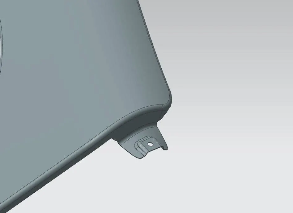
Pillars are vertical to supports on vehcile. They are located around all the glass on an automobile. They are important for hiding glass in place and adding structural integrity to a vehicle, primarly the roof.
The A pillar holds the winshield in Place. B pillar at the end of the first door. They usually offer substantial structural support for a vehicle's roof. Most of the time they are bound to the body frame and wrap all the way into the roof. Depending on the design, there may be mutiple pieces attached to increase integrity of the roof. They are also responsible for where a door's latch connects to the body. C Pillar hold a vehicle's rear window in place.
PROCEDURE:
Similar to that of design of Spill/ Bumper mountings.
- Draw few splines as per requirement with the help of curve on surface command to remove improper surface on previously extended sheet while designing drip area.
- Now trim off the improper surface.
- For Emboss Creation - Create Datum planes on the particular face or draw a sketch on parallel datum plane and project it. Use Emboss command, select the curves and datum plane in end cap portion to create emboss.
- For Hole Creation - Draw circles on previous sketch, trim off the portion by selecting proper faces & sketches in target and boundary option.
- Make sure that no sharp edges were left over which will later create problem while thickening. If found give some reliefs using bridge curves/curve on surface and trim it off.
- Blend the created embosses and joints using face blend.