Fender Design
AIM
To create Fender design by using given Class A surface. For the Sill, Bumper, Baffle(Splash), and A-Pillar mount create your own design according to the Engineering standard that you learned. Prepare a report with all the relevant images included for the mounting points created.
FENDER
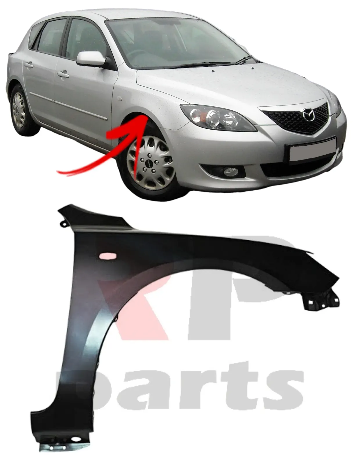
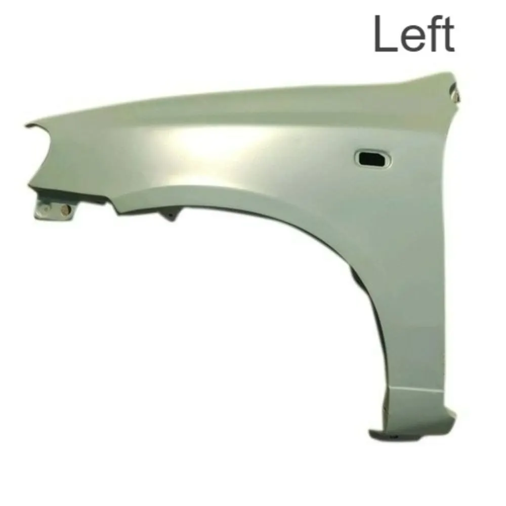
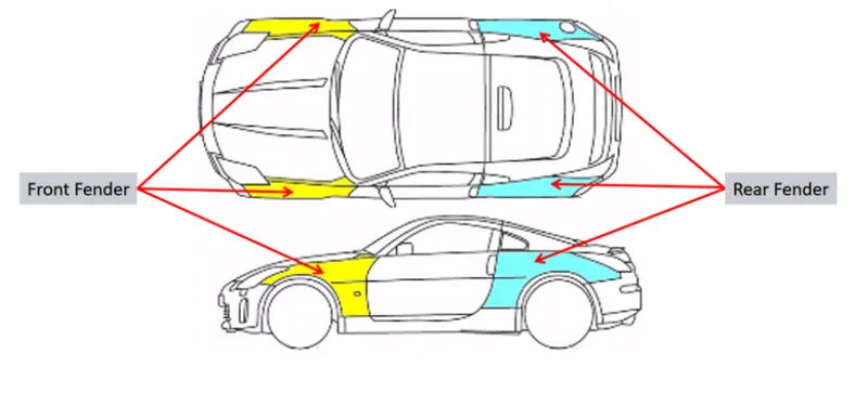
Fender is a part of automotive vehicle body that frames a Wheel well. Its primary purpose is to prevend sand, mud, rocks, liquids and other road spray form being thrown into the air by rotating tyre. Fenders are typically rigid and can be damaged by contact with the road surface. The fendre also act as a cosmatic part which hides the BIW components present inside and the ugly regions of the vehicle.
TYPES OF FENDERS
1.Full bumper fender
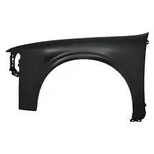
Full bumper type fender covers the area all the way from head lamps till the A-pillar of the car. The full bumper type fender were used in old cars.
further realised this type of fender consump more raw materials and Scrap, due to this manufacturing cost increased, thats why this type fender not in use today.
2.Half bumper fender
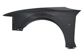
In half bumper type, the front portion is reduced till where the head lamp ends, because to reduce the raw material scrap, If the blank size will increase, so that it could be accomodate the other side fender. so that the processcould manufacture fender on both side at same time. Therefore manufacturing process becomes more cost effective & time saving.
MANUFACTURING PROCESS OF FENDER
Metal stamping process is commonly used in automotive vehicle body manufacturing by OEM.
Metal stamping process
The process of turning sheets of metal into a useful part or component is called sheet metal stamping. The metal is fed into a press, where the stamping tool, also known as a die, creates the desired shape. The die is pressed into or through the metal with tremendous force.
Common Sheet metal stamping process:
There are basically only three components to sheet metal stamping—the sheet metal, die, and press machine—but any single part can require multiple steps to arrive at its final form. The following guide explains a few common processes that might occur during metal stamping.
- Forming: Forming describes the process of transforming the flat metal into another shape by applying force. It is accomplished in one of several ways, depending on the design specifications for the part. With a series of operations, the metal can be altered from a relatively simple shape into a complex one.
- Blanking: Blanking is the most basic technique and initiates when the sheet or blank is fed into the press where the die cuts out the desired shape. The resulting piece is called a blank. The blank may be the desired part, also known as a fully finished blank, or it may continue to the subsequent step of forming.
- Drawing: Drawing is a more complicated operation and is how vessels or deep depressions are formed. Tension is used to carefully draw the material into a cavity to change its shape. Though the material might stretch while it’s drawn, technicians try to avoid stretching as much as possible to keep the material intact. Sinks, cooking equipment, and oil pans for vehicles are usually made with drawing.
- Piercing: Piercing is almost the opposite of blanking, but instead of saving the blanks, technicians use the material around the outside of the punched area. As an example, think of cutting biscuits from a rolled-out circle of dough. During blanking, the biscuits are saved; during piercing, on the other hand, the biscuits are discarded, and the hole-riddled remains are the desired outcome.
FENDER MOUNTING AREA & DESIGN PARAMETERS
Basically fender is mounted on following areas:
- Drip
- Sill
- A-pillar
- Bumper
- Baffle cover
1.Drip mounting design
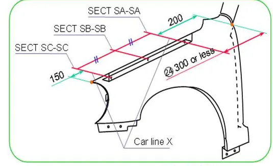
Drip area mounting is the part which connects the fender with the engine compartment. We use fasteners for joining the component. Designing the drip area has few constraints that there must be enough space at the front and rear end of the fender. At the rear end there needs to be space for the cowl top mount which carries the cowl top along with the wiper motor arrangement.The front end we know that the headlight arrangement occupies at least 150 mm. So now this must be attached to the engine compartment. This must be designed so that from seeing from outside there should not be any ugly components visible. And this part should be given embosses to avoid spring back effect
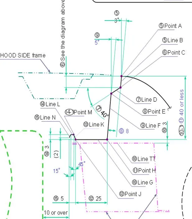
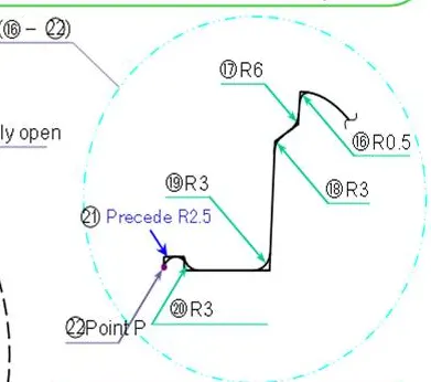
As per given master section for drip mounting area design, we design the drip area cross section
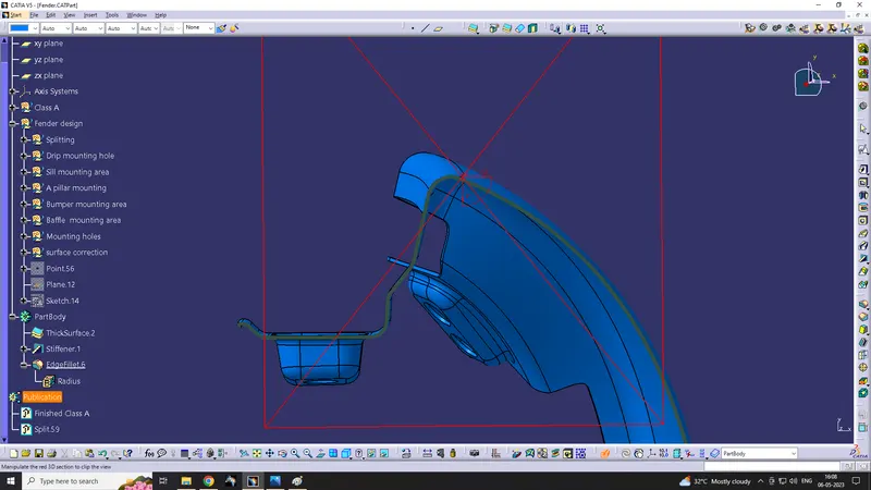
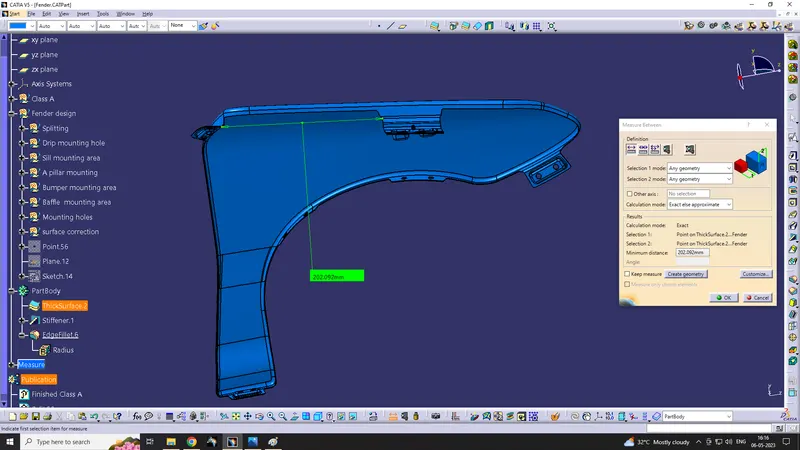
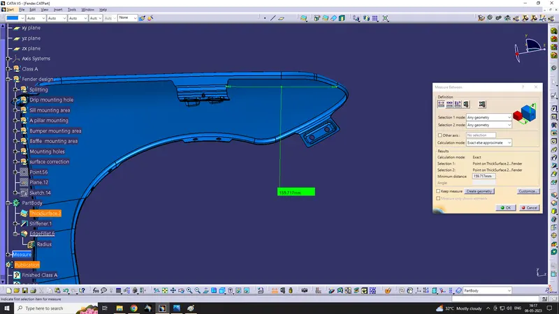
As per the master section, gap to be maintain for head lamp assembly must be greater than 150mm & for wiper assembly must be greater than 200mm
so gap 202mm is maintained at wiper assembly side
and gap 159mm is maintained at head lamp assembly side
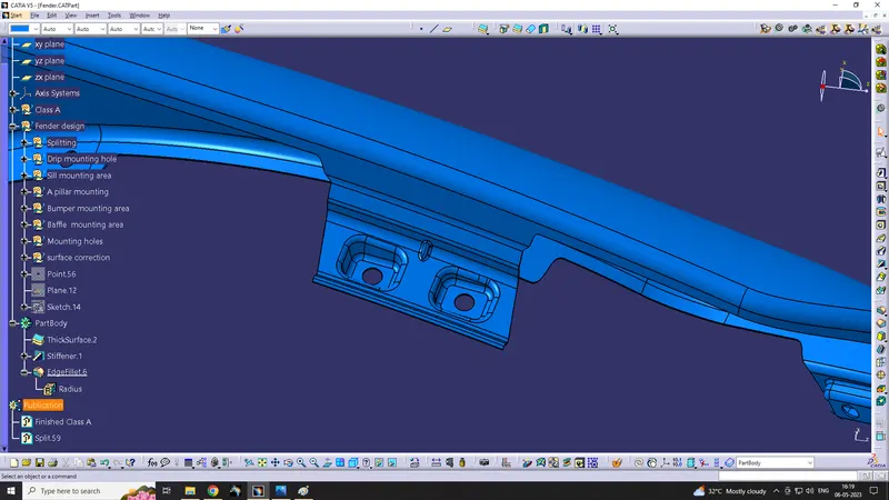
On emboss hole area, flat surface is provided to mount on flat surface. So the final design is given below.
2. Sill mounting
Sill mounting is used to mount fender on sill region. Sill is the under side portion of door.
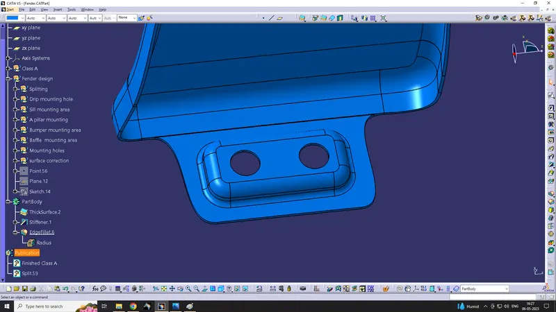
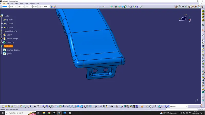
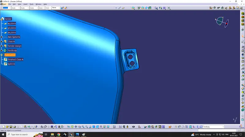
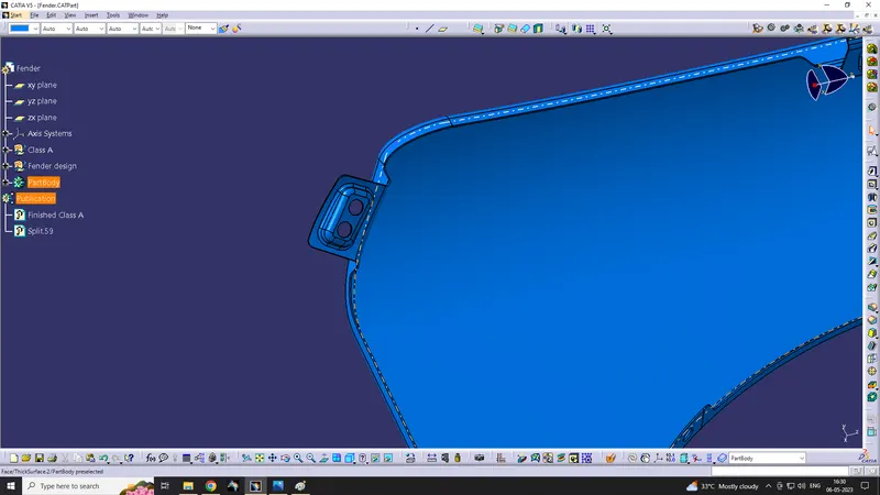
3. A-pillar mounting
This connect fender with A-pillar. A-pillar ia the structure that combines body with roof
4. Bumper mounting
This mount connect fender with bumper area.
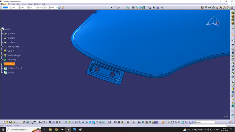
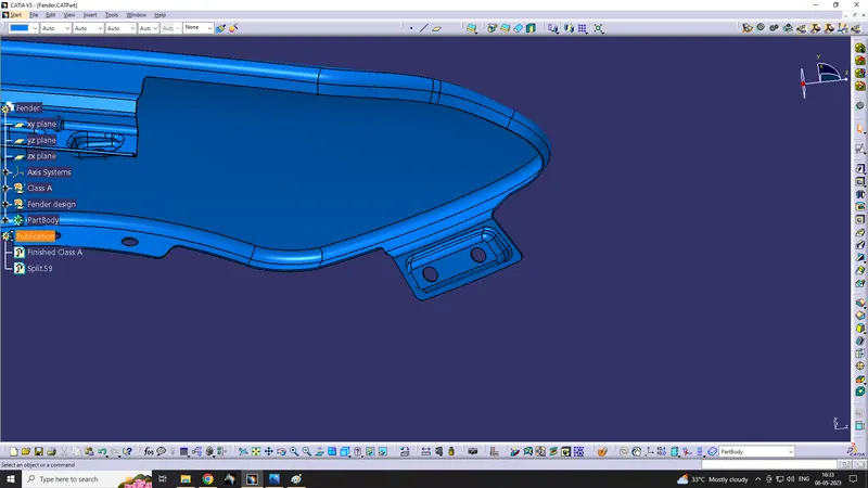
5. Baffle mounting
baffle or Splash cover protects the engine compartment area by entering car tyre debris. basically it is made by plastic & mounted with fender.
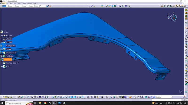
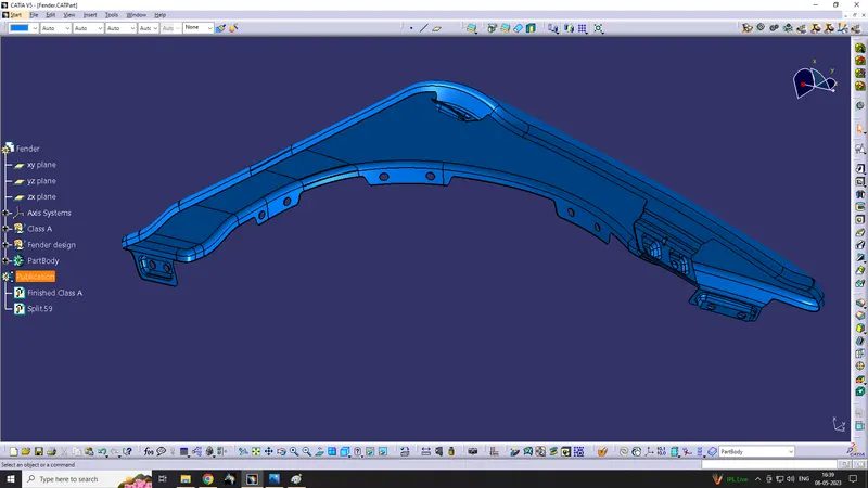
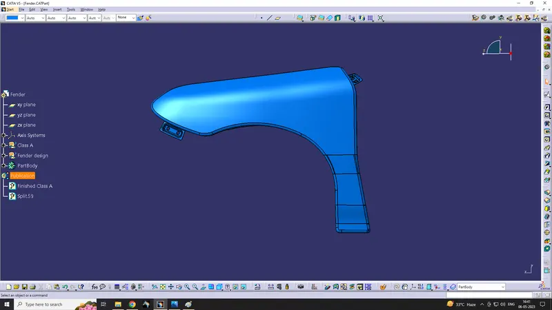
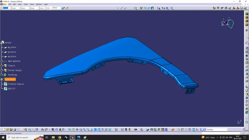
Final Fender Design
CONCLUSION
Thus, Fender is designed as per the given master section.