Fender Design
AIM: To design a front fender of a car by following the given master section as per the design considerations of OEM.
INTRODUCTION
Fender is the american english term for the part of an automobile, motorcycle or other vehicle body that frames a wheel well. Its primary propose is to prevent sand, rocks, mud, liquids, and other road spray from being thrown into the air by the rotating tire. Fender are typically rigid and can be damaged by contact with the road surface.Sticly materials, such as mud, may adhere to the smooth outer tire surface, while smooth loose objects, such as stones, can be become temporarily embedded in the tread grooves as the tire rolls over the ground. These materials can be ejected from the surface of the tire at high velocity as the tire imparts kinetic energy to the attached objects. For a vehicle moving forward, the top of the trie is rotating upward and forward, and can throw objects into the air at other vehicle or pedestrians in front of the vehicle. Fender is a front outer side member of a car, which covers the wheel side. It has so many small features with ups and downs.
FENDER
It is an aesthetic component/part of a car that frames the wheels. Prevention of sand, mud particles, and other road contaminants from being thrown into the engine compartment and also to the pedestrians by the rotating tires are the main purpose served by the fenders.
The front fenders are separate components whereas the rear fenders are integrated with the body sides.
TYPES OF FENDERS
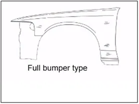
1. FULL BUMPER TYPE: These types of fenders were used in earlier models of vehicles. They contribute to the major increment of the steel weight by just covering the front headlights with respect to the bumper region. The problem associated with this kind of fender is there is a lot of wastage in the blank and every inch of a material is a cost to the industry.
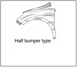
2. HALF BUMPER TYPE: These fenders are mainly used for serving the purpose of cost-cutting and reducing enough proportions of the steel wait resulting in a reduction of the weight of the vehicle slightly. They can be economically manufactured, i.e by slightly increasing the blank size, we can produce two fenders at a time.
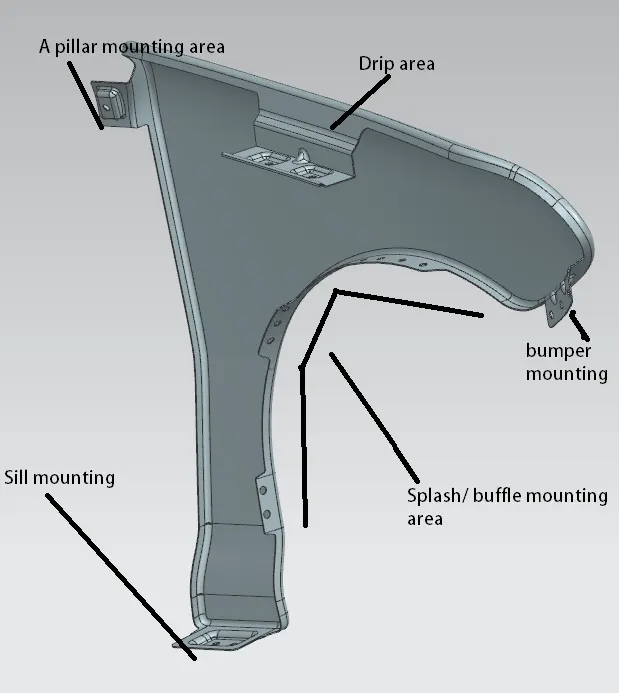
MOUNTING REGIONS ON FENDER :
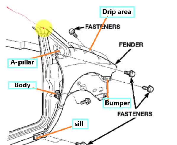
There are 5 mounting regions on the fender , they are
- A- pillar mounting
- Body mounting
- Sill mounting
- Bumper mounting
- Drip mounting
Master Section:
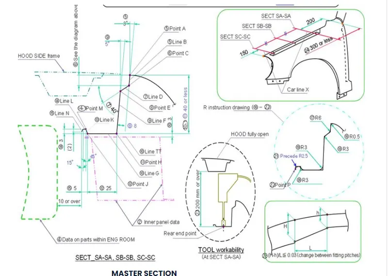
DESIGN OF DRIP AREA MOUNTING
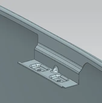
STEP 1 : Use law extension from the given flanges of the fender following the master section.
STEP 2 : Give face blends to all the law extended flanges.
STEP 3 : Sketch the mounting area face and holes of 5 mm dia, holes should have 10mm dia flat surface.
STEP 4 : Project the sketch on the drip area surface.
STEP 5 : Create a datum plane to give emboss to that respect.
STEP 6 : Give emboss of 3.5mm.
STEP 7 : Trim sheet for holes.
STEP 8 : Give face blends to emboss.
STEP 9 : Create Dart in the middle of two emboss.
STEP 10 : Give edge fillet yo dart and make sure there are no any sharp edges and should have smooth transition of surfaces.
PROCEDURE TO CREATE SILL AREA MOUNTING
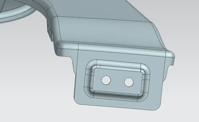
STEP 1 : Extend the sheet of the fender from its edge of the sill area.
STEP 2 : Create a datum plane with respect to the extended surface.
STEP 3 : Sketch the mounting area face and holes of 5 mm dia, holes should have 10mm dia flat surface.
STEP 4 : Give an emboss of 3.5mm with an end cap as the plane we created earlier.
STEP 5 : Trim sheet for holes.
STEP 6 : Give face blends to emboss.
PROCEDURE TO CREATE A PILLAR AREA MOUNTING
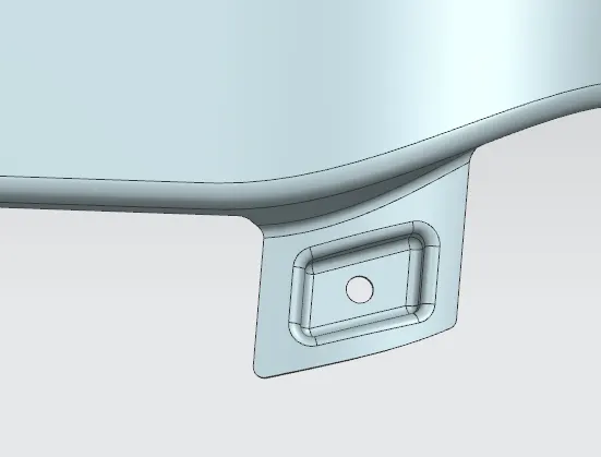
STEP 1 : Bridge the curve to the both corners of the extended sheet.
STEP 2 : Trim the sheet to avoid sharp corners.
STEP 3 : Create a datum plane with respect to the extended surface in offset of a few millimeters above the surface and select the sketch orientation.
STEP 4 : Sketch the mounting area face and holes of 5 mm dia, holes should have 10mm dia flat surface.
STEP 5 : Project the sketch on the A pillar area surface.
STEP 6 : Create another datum plane with respect to the extended surface.
STEP 7 : Give an emboss with an end cap as the plane we created earlier.
STEP 8 : Trim sheet for holes.
STEP 9 : Give face blends to emboss making sure that there are no any sharp edges and should have smooth transition of surfaces.
PROCEDURE TO CREATE BUMPER AREA MOUNTING
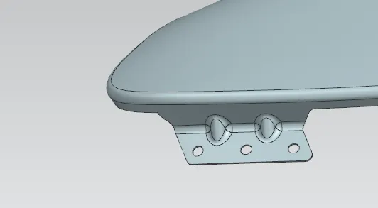
STEP 1 : Use law extension to the 90 degrees of the face and 20 mm length.
STEP 2 : Bridge the curve to the both corners of the extended sheet.
STEP 3 : Trim the sheet to avoid sharp corners.
STEP 4 : Create a dart in the middle of the extended sheet and fender flange.
STEP 5 : Give an edge blend of 3mm.
STEP 6 : Create a datum plane with respect to the extended surface.
STEP 7 : Trim sheet for holes.
PROCEDURE TO CREATE BAFFLE AREA MOUNTING
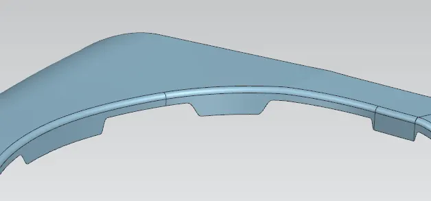
STEP 1 : Offsetting the curve of face blend edge to 5mm below.
STEP 2 : Creating bridge curve from offsetted curve to edge of the fender to show smooth transition of surface after trim at three portions of fender to create baffle mounting.
STEP 3 : Trimming the surfaces.
STEP 4 : Create a plane few millimeter above the surface of the the fender
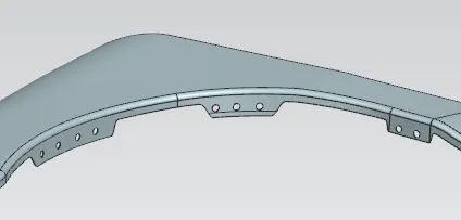
STEP 5 : Sketch the two circles of 5mm dia, holes should have a 10mm dia flat surface and have a large distance between them.
STEP 6 : Project the sketch to the surface.
STEP 7 : Trim the sheet to show the holes on the baffle area.
STEP 8 : Do the same for the rest of two baffle areas as shown in the picture below.
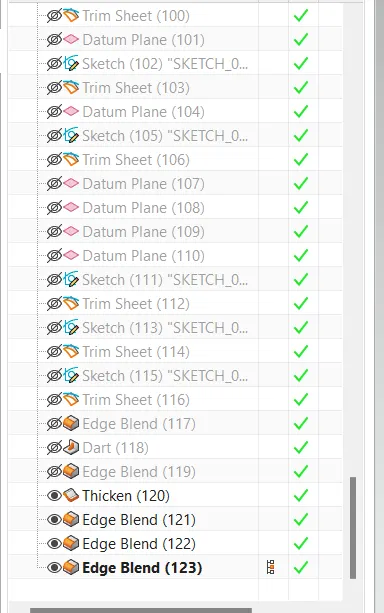
STEP 9 : Thicken the Fender Part
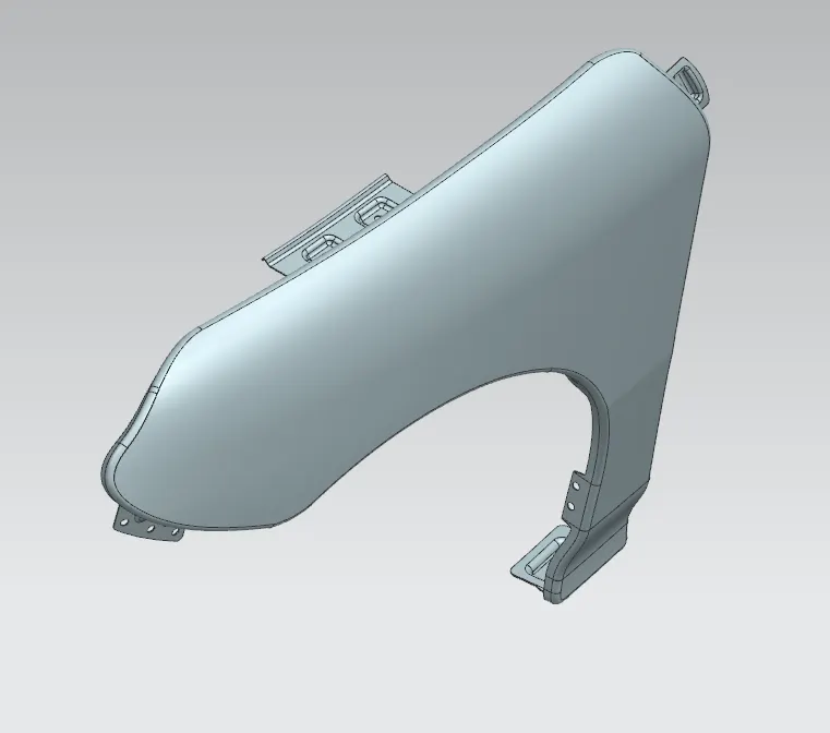
RESULTS
Designing Front Fender and the necessary mountings are done as per the Master section with the design parameter an final model
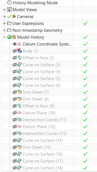
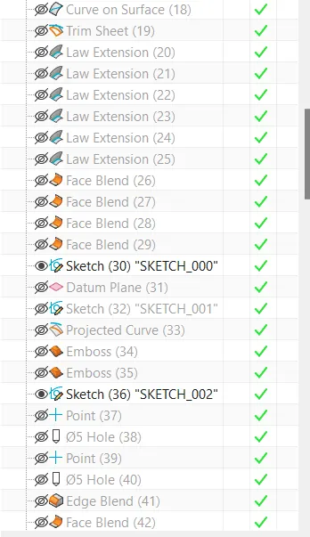
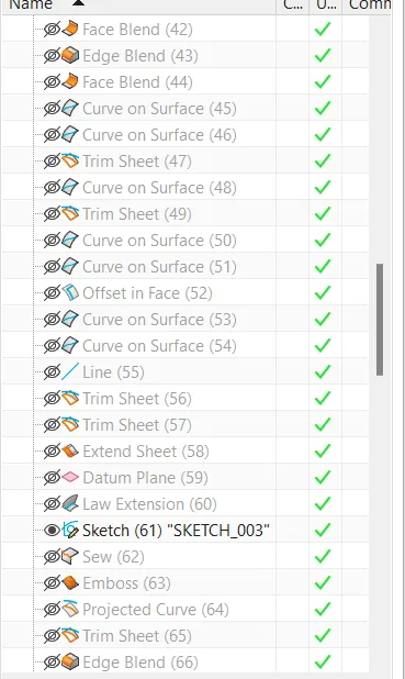
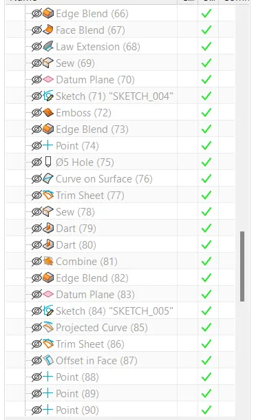
design tool i used in this model
Conculsion
I learn the design processer any car fender through NX