Fender Design
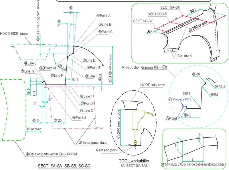
AIM - To design a front fender of a car by following the given master section as per the design considerations of OEM. Follow the given Master section to create the Drip Area , the Sill, Bumper, Baffle(Splash), and A-Pillar mount .
INTODUCTION -
FENDER -
Fender is the American English term for the part of an automobile, motorcycle or other vehicle body that frames a wheel well (the fender underside). Its primary purpose is to prevent sand, mud, rocks, liquids, and other road spray from being thrown into the air by the rotating tire. Fenders are typically rigid and can be damaged by contact with the road surface.
Sticky materials, such as mud, may adhere to the smooth outer tire surface, while smooth loose objects, such as stones, can become temporarily embedded in the tread grooves as the tire rolls over the ground. These materials can be ejected from the surface of the tire at high velocity as the tire imparts kinetic energy to the attached objects. For a vehicle moving forward, the top of the tire is rotating upward and forward, and can throw objects into the air at other vehicles or pedestrians in front of the vehicle.
types of fender
there are mainly two types of fender designs
- full bumper type
- half bumper type
1- full bumper type -
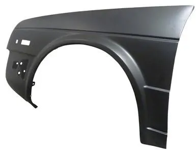
The full bumper type fender was used in old cars, it covers the full area until the front lighting. But it has a lot of sheet metal material which is unnecessary and increases the weight of the fender. This type of fenders are no longer used in automobiles.
2- Half bumper type -
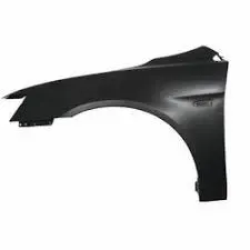
Half bumper type is the modern design where less material consumption is observed, so productivity increases by reducing the size of the blank and thus providing more performance. The maintenance also relatively low compared to the full bumper type.
We are changed from full bumper type to half bumper type to reduce the scrap rate per blank. In the full bumper, we can only produce one Fender per blank, whereas as a half bumper type we can produce 2 fenders per blank.
Half bumper fender type is also cost effective than full bumper type fender due to low steels used for half bumper.
Procedure
Before start working on fender design we have to consider the regulations provided by
1.EUROPEAN REGULATION REQUIREMENT
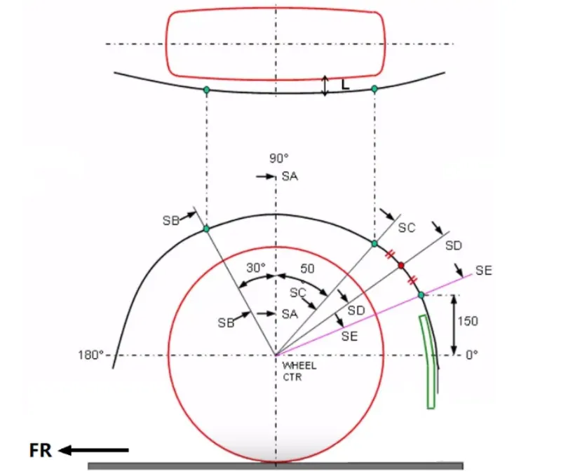
Measure CL L at section SA-SA-SB-SB-SC-SC-SD-SD-SE-SE and produce CL check chart to validate.
- At all five sections the CL L value should be greater than 10mm to satisfy the European regulation.
- Wheel guard requirement: the value of a .Shall be more than 5mm at a line 30 degree forward and 50 degree rearward from the central verticalaxis of axis of wheel.
now,
we are provided with the fender skin
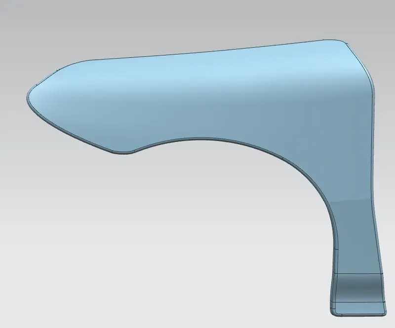
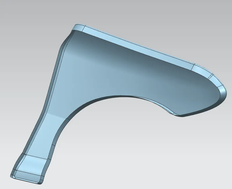
1: A-pillar mounting
To create a location point for the drip region 1st we need to create a A-pillar mounting .
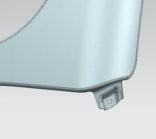
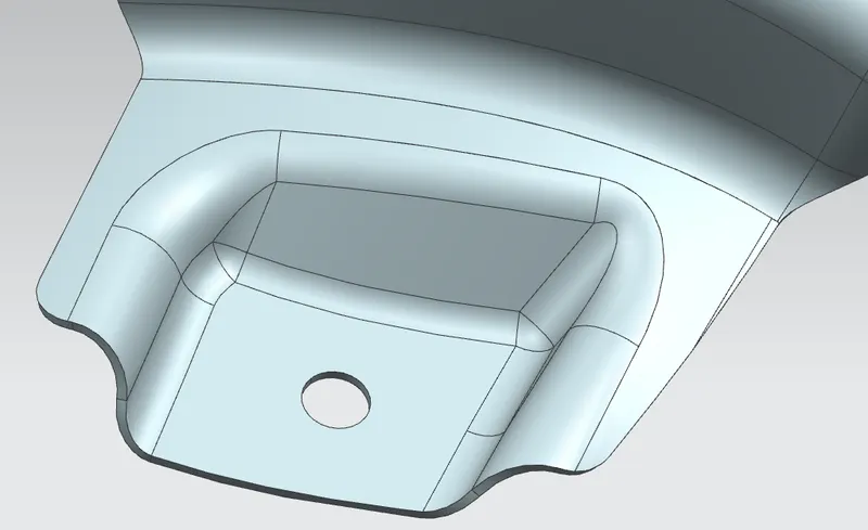
features & steps used to make A-pillar mounting
- offset curve 5mm .
- use law extension of 30mm
- create a datum plane using infered feature select the center of the law extension surface.
- create sketch with proper dimensioning
- project curve feature to project the sketch on the surface .
- use emboss command to emboss the surface
- use fillet edge command with 3.75mm radius.
- make a cut-out for fasteners using trim sheet.
2: Drip area -
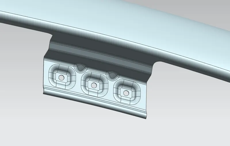
this area is created according to the parameters provided by master section in the above figure.
* features & steps used to make a Drip Area.
- create datum plane from the lower end point of the A-Pillar mounting then offsetting it 190mm.
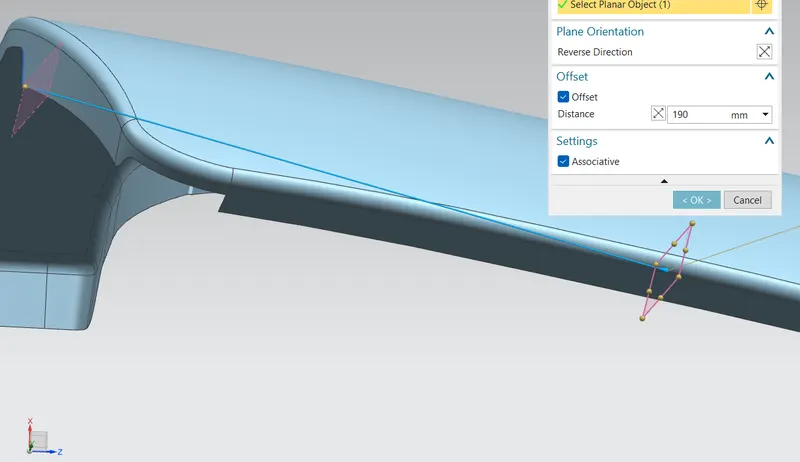
- create another datum plane from the head light region offset it 150 mm
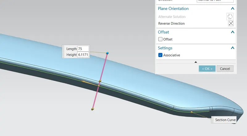
- using law extension create section area
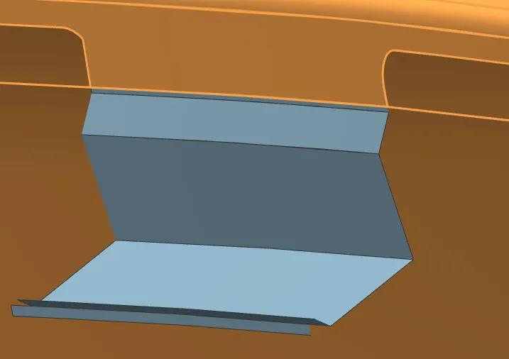
- provide fillets according to the standards.
- then create a sketch on a plane normal to the surface
- use project curve to project the sketch on the surface.
- use emboss command to emboss the surface
- use fillet edge command with 3.75mm radius.
- make a cut-out for fasteners using trim sheet.
- add two darts using dart command to strenthen the drip area due to its large surface.
dripp area is completed.
Bumper mounting :
It is a mounting used to fasten on the bumper region.
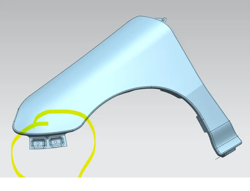
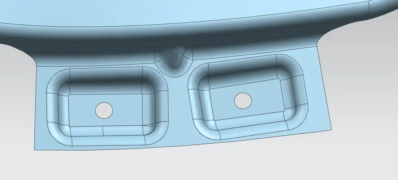
features & steps used to make A-pillar mounting
- select the edge of the fender skin model.
- use law extension of 30mm
- create a datum plane using infered feature select the center of the law extension surface.
- create sketch with proper dimensioning
- project curve feature to project the sketch on the surface .
- use emboss command to emboss the surface
- use fillet edge command with 3.75mm radius.
- make a cut-out for fasteners using trim sheet.
- create single dart for strenghening.
Sill mounting :
sill mounting is a part used to hold the fender from the botttom.
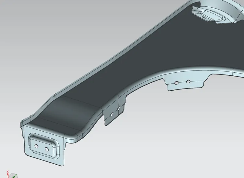
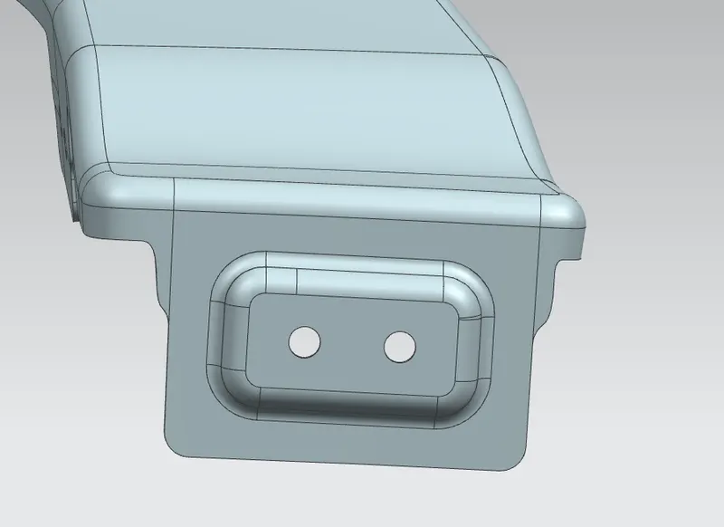
features & steps used to make
- use law extension .
- create a datum plane using infered feature select the center of the law extension surface.
- create sketch with proper dimensioning
- project curve feature to project the sketch on the surface .
- use emboss command to emboss the surface
- use fillet edge/face command with 3.75mm radius.
- make a cut-out for fasteners using trim sheet.
- make sure to remove all the sharp edges.
Baffle mounting :
Baffle mounting used to hold the plastic/fibre sheet that prevents the dirt,chips,mud,rough stones,etc. from going inside the engine compartment.
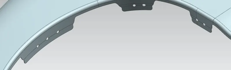
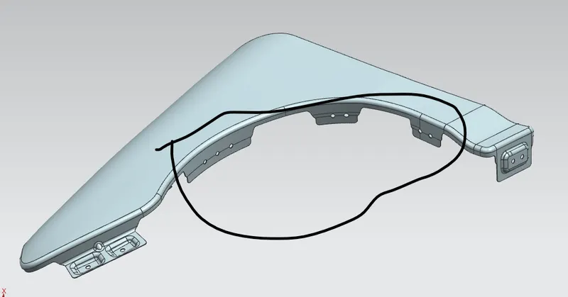
features & steps used to makebaffle mounting.
- use law extension command or you can can use the extend sheet option also.
- create a sketch on all three surface .
- then use project curve option to project the sketch on each surface .
- make cut-out for the fasteners using trim sheet option.
- make sure to remove sharp edges.
conclusion
All the mountings are created successfuly .