Fender Design
Aim:
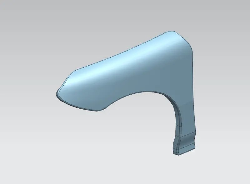
The main aim is to design the fender model with the necessary mounts using the class-A surface.
Mounts:
- Bumper
- A-Pillar
- Sill
- Cowl
- Drip
Theory:
Fender:
A fender is a part of an automobile that frames a wheel well (Fender underside). Its primary purpose is to prevent sand, mud, rocks, liquids, and other road sprays from being thrown into the air by the rotating tire. The fender's openings for the wheel wells tend to be much larger than the diameter of the tire because they do not move with the tire suspension and consequently must be large enough to allow the full range of tire motion on the suspension without touching the interior of the wheel well.
Types of Fender:
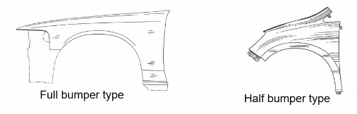
Full front fender:
If the fender covers the tire, the wheel well surrounding the tire, and it is not directly visible from above the car body. It increases the weight and scrap of the component.
Half front fender:
It reduces the weight and scrap. It creates only half of what the full front fender does and the other part is created with the bumper part.
DESIGN PARAMETERS -
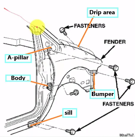 The front fender is manufactured as a separate part , this is then mounted to the body of car , for this the front fender basically has 5 mounting points, but this mounting points can differ from OEm to another OEM .below is the points -
- Drip area- Drip area mounting is the important part in the fender . this mounting is attached to the engine compartment of the car . fender drip area is mounted via weldnuts to the engine compartment .a min of 150mm distance is kept from the front side and a distance 300mm or less can be kept on the rear side . the total length of drip area from the top of fender should be less than 40mm , this is to avoid the springback during the manufacturing . the edge of the mounting should atleast 10mm away from any nearby component in the engine . a rigidity bead is provided at the end to increase the strength of the mounting .
A-pillar area -
The A-pillar area mounting depends upon the A-pillar of the car . the mounting can also be provided with ribs to strengthen the part . this mounting is critical in design as it has to be mounted on A-pillar properly .
- Sill area -
Sill area mounting is also an important mounting part .this mounting point is basically on the bottom of the fender . the mounting part should be created such that the fender is firmly attached to the sill .
-
Bumper Mounting Area
The bumper mounting region is located beneath the bumper. The fender gets attached before the installation of the bumper. After fixing the fender with fasteners the bumper will cover the bumper mounting - Baffle Mounting Area
In this region, the baffle gets installed to the fender with the help of clips which holds the baffle with the fender along the wheel arch. - Input - we have the outer skin of fender as our input .
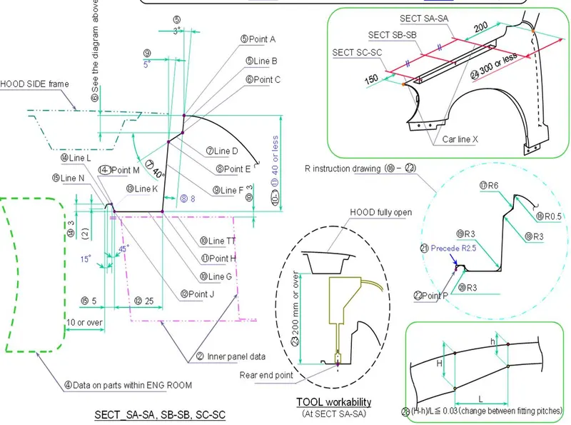 master section for drip area mounting 1) Drip area -
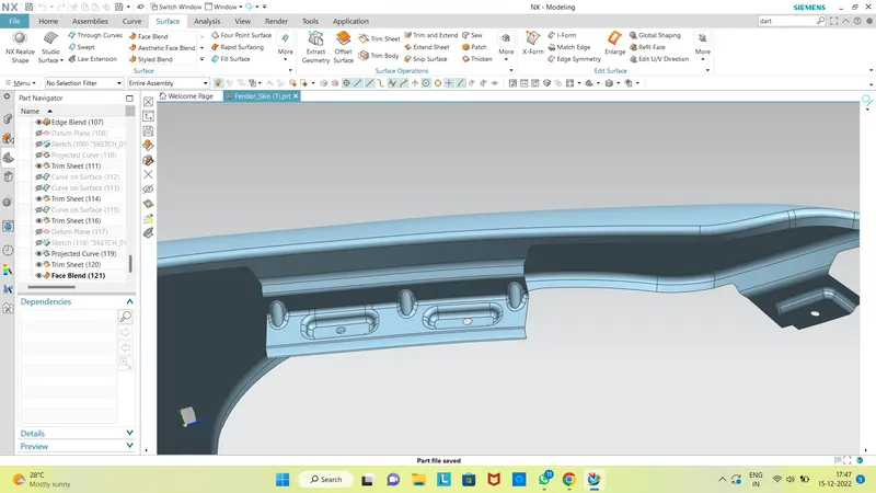 The height of drip area mounting should be less than 40mm so that it reduces the springback effect during manufacturing .
The edge of the mounting part should be atleast 10mm away from the nearby components in the engine .
It should be distanced atleast 150mm from the front side ande 200m from the rear side .
Ribs should be provided in order to increase the strength of the mounting part .
Bead is provided at the outeredge to increase the rigidity of part .2 ) A-pillar -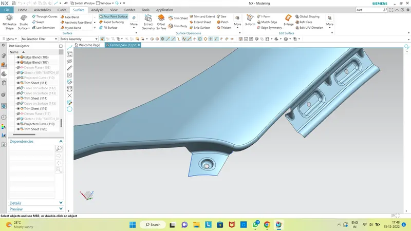 Bumper side -
 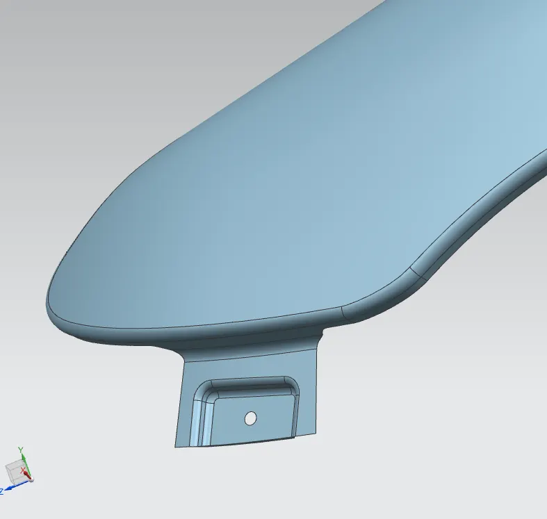 Sill area mounting -
 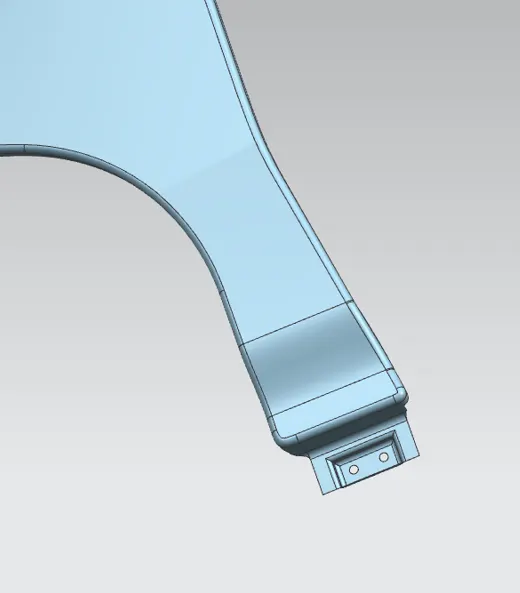 5) Baffle mounting
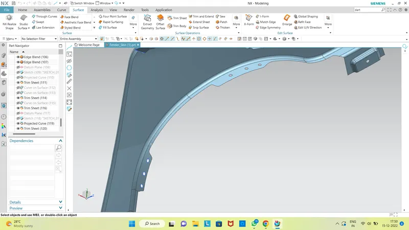 For improvement of NVH in car , usually a baffle is mounted on the fender of the car . it is mounted on the wheel arch area Output -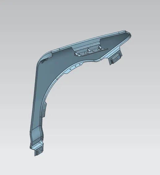
CONCLUSION -
We have developed front fender with mounting points following the design parameters and mastersection
- Drip area- Drip area mounting is the important part in the fender . this mounting is attached to the engine compartment of the car . fender drip area is mounted via weldnuts to the engine compartment .a min of 150mm distance is kept from the front side and a distance 300mm or less can be kept on the rear side . the total length of drip area from the top of fender should be less than 40mm , this is to avoid the springback during the manufacturing . the edge of the mounting should atleast 10mm away from any nearby component in the engine . a rigidity bead is provided at the end to increase the strength of the mounting .