Fender Design
Fender Design
FENDER
- Fender is the part of a car that protects and frames its wheels and keeps mud from splashing it. Most modern vehicles have fenders on their front wheels. It is the part of a car, truck or motorcycle that surrounds the wheel sell.
- The primary function of a fender is to prevent dirt and debris from being thrown into the air by the tire. The fender is located over the wheels of the vehicle. As such,there are four fenders on a typical vehicle: front right,front lef t, rear right and rear left.
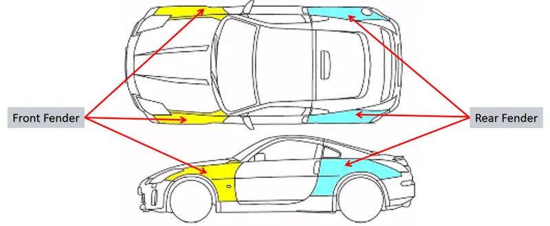
Types of Fenders
1) Full fender type
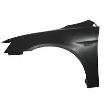
Full fender typeis traditional type of fender where more material consumption is observed. This type is used in old design of automobiles where it increases the overall weight and thus reduces performance.
2) Half fender type
Half fender type is modern design where less material consumption is observed,so productivity increases by reducing size of blank and thus providing more The maintenance also relatively low compared to full bumper type.
Different types of fender mounts and its design parameters
1)Body mounting
2)A pillar mounting
3)Sill mounting
4)Cowl mounting
5)Drip mounting
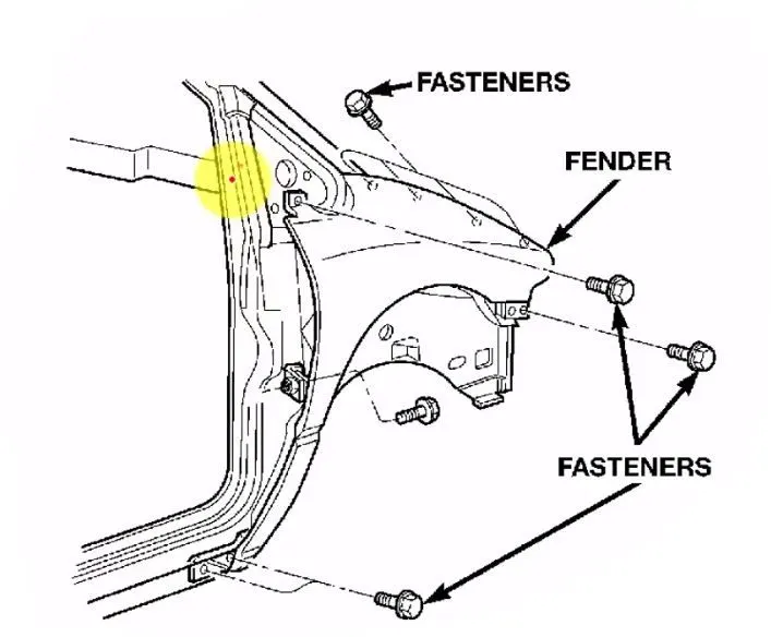
- From the above design requirements, the Drip area is the most important area for designing the fender. For fender drip area we are having various regulations to design for the pedestrian safety and for easy fixation of the fender with the engine compartment of the vehicle.
- The fender drip area always should have the following clearances for the ,ounting purposes. From the viper motor mounting region the fender should atleast have 200mm clearance then only the mounting of the fender by the use of the power tools also will be easy. It is shown below.
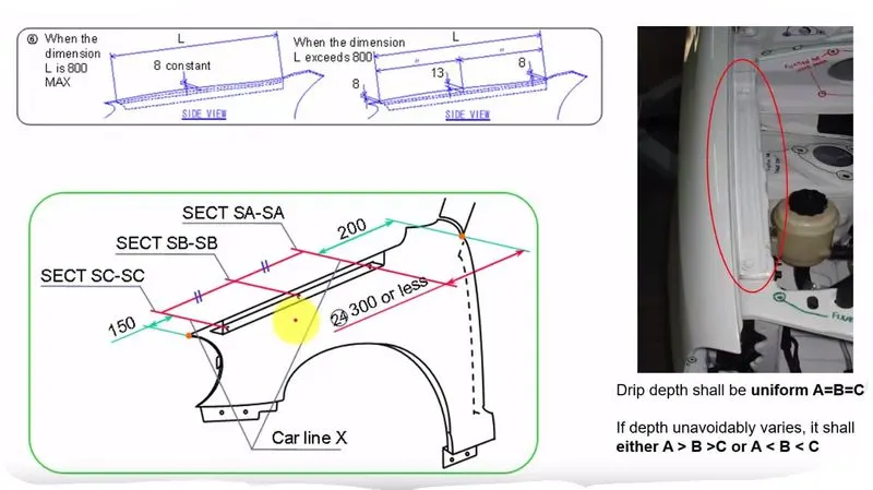
- The 200mm gap maintained from the one end of the fender will give the good tool workability for the fender while assembling it with the help of power tools.
- And the drip area should maintain atleast 150mm of gap from the head light mounting area. To make the clearance for the head light mounting provisions, and the drip sholud have atleast 10mm of clearance for not making any damage to the other inside components while installing the fender to the vehicle.
- Another design regulation is we should follow the master section of the fender provided, this master section is shown below and their purposes are given in the below image.
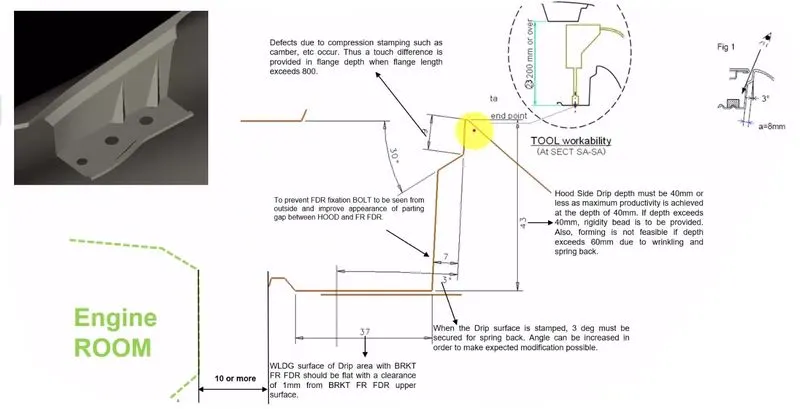
- Here we are following the inclination angle of 3 degree for making the flange to hide the inside bolting and fixation area when customer is seeing from the side of the car. And the flange should have a little opening angle from the fender surface to have a good manufacturability.
- The maximum length of the fender should not go beyond 60mm, if it goes beyon 60mm there will be some spring back effect, this will cause the fender drip area to deform its posistion after pressing or stamping process. So here in this design it is kept for 43mm.
- And the 10mm clearance gap is provided for the flange to the other components in the surronding of the fender in engine compartment area to avoid any collisions while assembling the components.
Side reference line
- Another important safety factor while designing the fender is side reference line. The can be explained from the below image
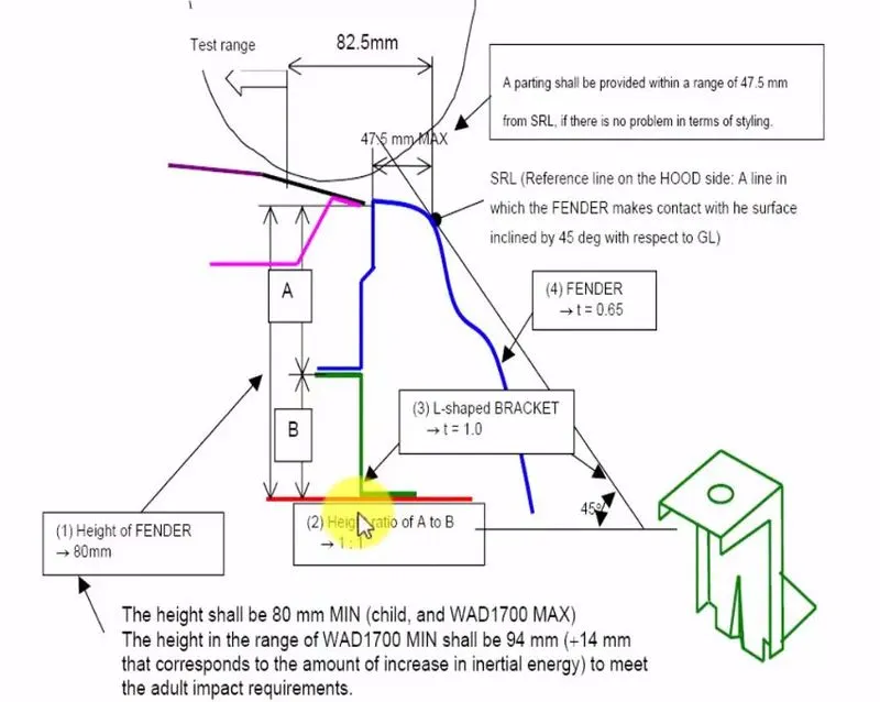
- In the above image the side reference line is shown, the side reference line is the line drawn for 45 degree from the ground level touching it to the fender.
- For the pedestrian safety the distace between the side reference line touching point with the fender to the edge of the fender should be lower than 47.5mm, the maximum value is 47.5mm it ahould not go above it, for the pedestrian and wrap around distance this value is maintained.
- If the skin data of the fender from the studio is not having this value we need to inform the styling team to make the change in the class A surface.
Manufacturing process of fender
- Open straight snips plate and first select applicable cold coiling specification, cold coiling is opened flat.
- Then according to production material specification, will open cold coiling after flat and be cut into into the iron plate of corresponding size.
- Finally the iron plate after shear is cleaned to iron filings.
- Oil pressure, punch press are first applied on iron plate and extended.
- Secondly to its trimming and punching.
- Then to its flanging and shaping
- Finally after shaping completes, then carry out one-off hole-piercing; Completed the making of lappet plate body.
- The smallclothes of processing lappet and first iron plate is stamped out to required outline blank (blanking).
- Then to completing the further moulding of iron plate of outline blank.
- Finally it is carried out to punching.
- In Panel beating assembly welding the smallclothes are carried out to spot welding M6 nut and then 1st part point is welded on lappet.
- Finally lappet body and 1st smallclothes are carried out to sanding thorn and ending.
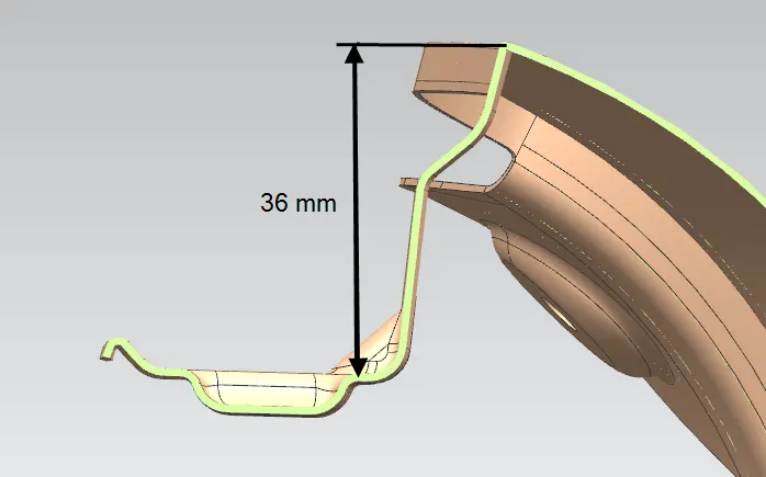
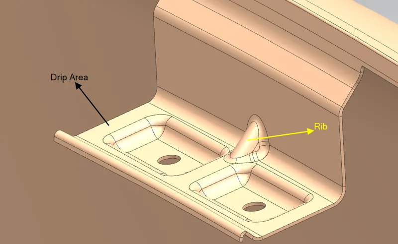
Drip mounting
A pillar mounting
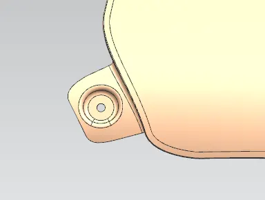
Sill mounting
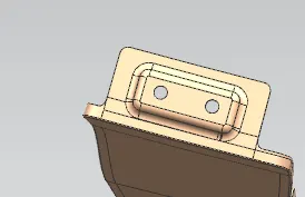
Splash cover mounting
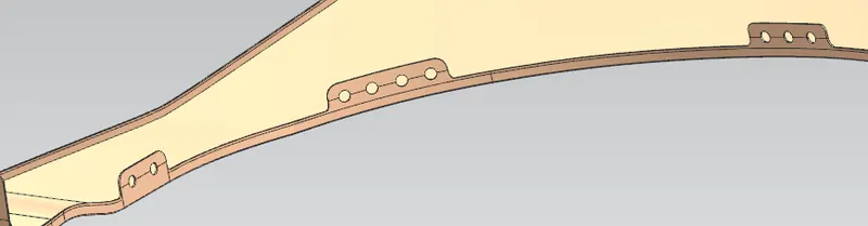
Bumper mounting
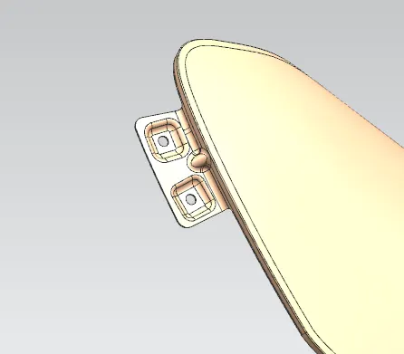
Final Fender Design
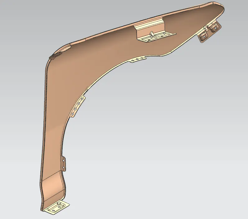
Conclusion
According to the Master section I create the Drip Area , Sill, Bumper, Baffle(Splash) and A-Pillar mount for the fender.