Fender Design
REPORT.
Fender Design Using NX.
OBJECTIVES:_ To design fender using classA surface and understand design consideration of fender design.study different aspect of automobile industry manufacturing.
FENDER
Introduction:_ It secondary covering of engine bay, fender is also part of asthetics of automobile and also important aspect in aerodynamics to reduce drag which improves performance of a automobile.
fender protects engine from foreign materials scattered due to motion of wheel. fendrer is also designed with consideration of pedestrian and passenger safety.
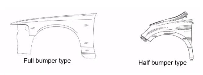
There are two types of of fenders
1. Full Bumper Type.
2. Half Bumper Type.
Manufacturing process
The manufacturing of the fender majorly involves these operations.
1.Embossing
2.Bending
3.Cutting and Blanking
DESIGN PROCEDURE
GIVEN MASTER SECTION
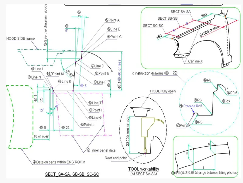
GIVEN CLASS A.
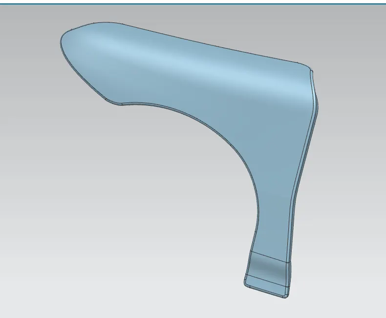
Figure. classA
Design Criteria:_
- Embosses are used to increase strength.
- Smooth curves are designed for easy manufacturing of product.
- Darts are provided to drip area mount to give structual support and extra strengh.
- Maintain extra 10mm from the flat surface for the fastner holes.
- All fillets should maintain 2 or 3mm radius in most regions.
- Thickness of fender is 0.75mm.
STEPS INVOLVED IN DESIGN.
design is according to mastersection provided.
- Drip Area mounting-
- A-pillar mounting -
- Bumper mounting-
- Sill mounting -
- Baffle mounting -
Drip mounting.
- While designing the drip we have to initially leave 200-300 mm for cowl top
- For placing the headlamp we have to leave at least 150 mm at the front while designing the fender
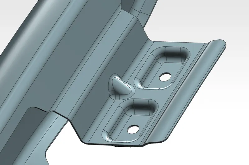
Figure.drip mount
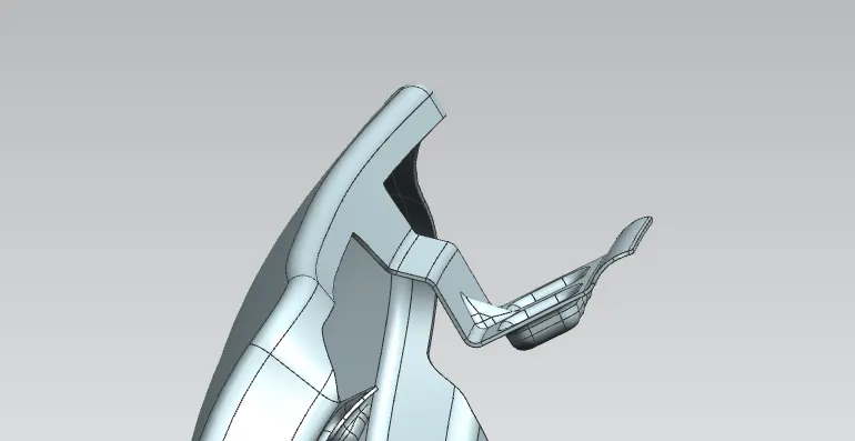
Figure.drip mount
sketch for fastneers and emboss.
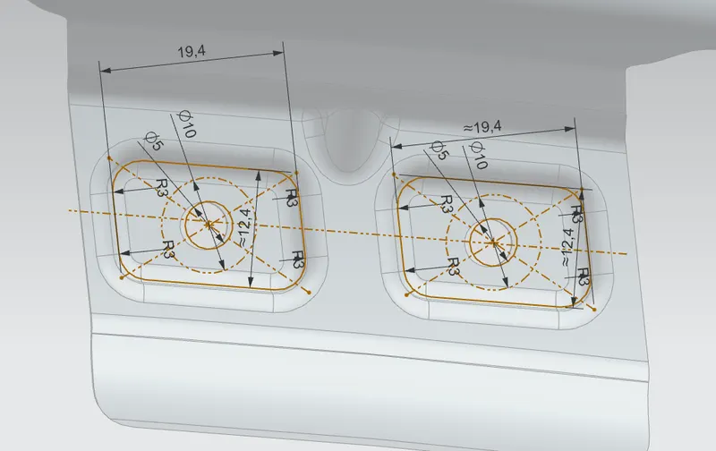
Figure.emboss sketch
A-pillar mounting.
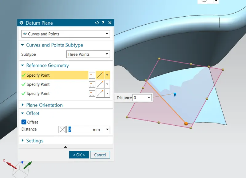
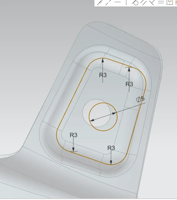
Figure.datum creation Figure.sketch
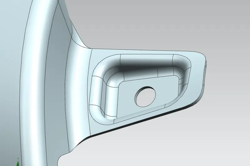
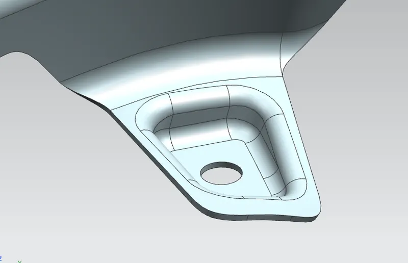
Figure.cowel mount Figure.cowel mount
Bumper mounting.
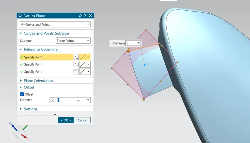
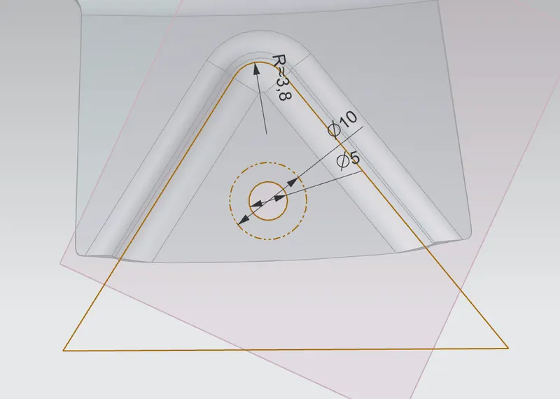
Figure.datum creation Figure.sketch
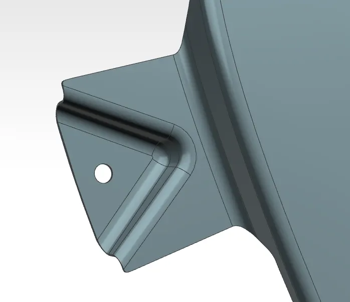
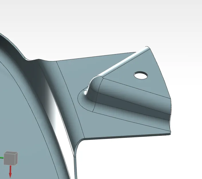
Figure.bumper mount Figure.bumper mount
Sill mounting.
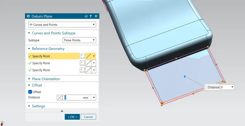
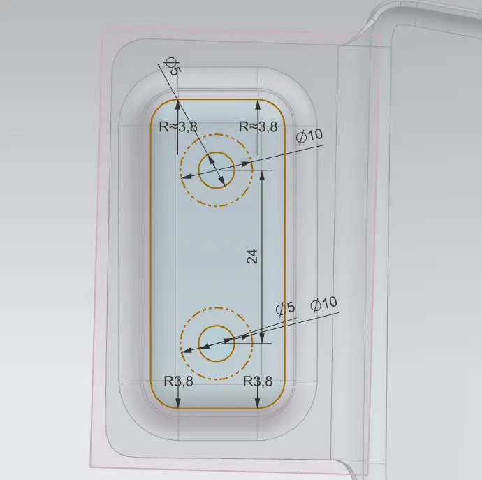
Figure.datum creation Figure.sketch
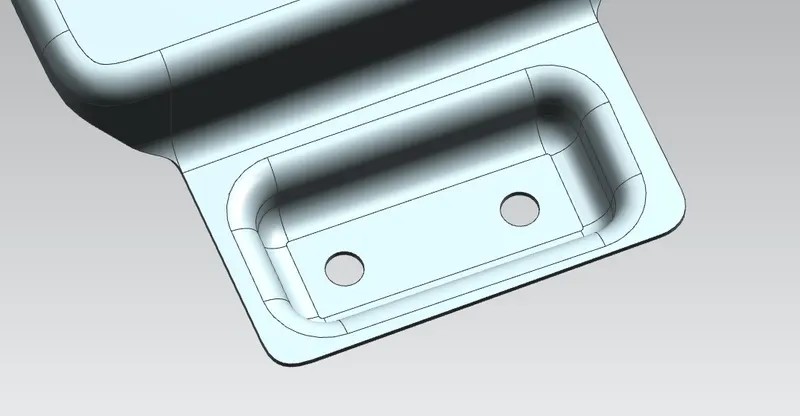
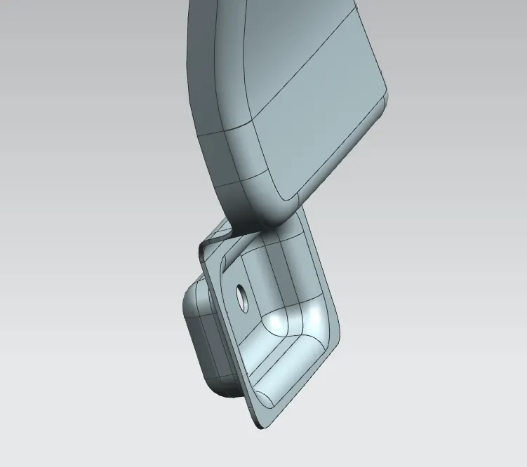
Figure. sill mount Figure.sill mount
Baffle mounting.
for baffle mounting plastic componant is fitted using push clips, only holes cutout should be given.
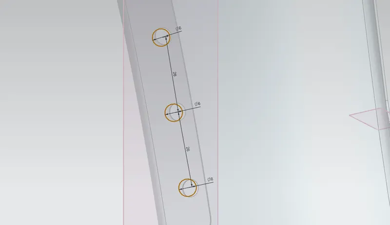
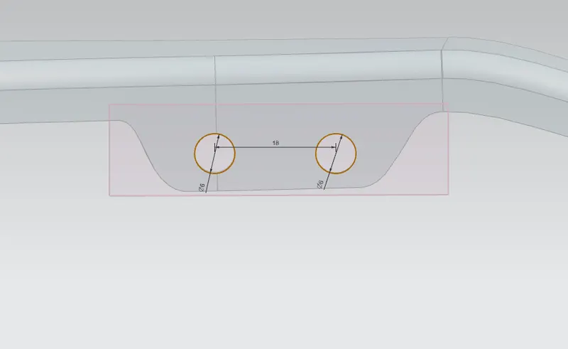
Figure.sketch1 Figure.sketch2
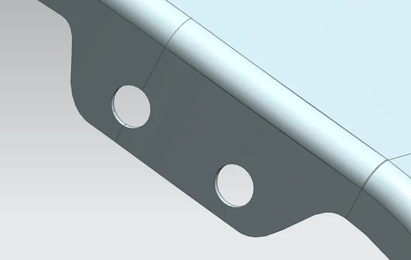
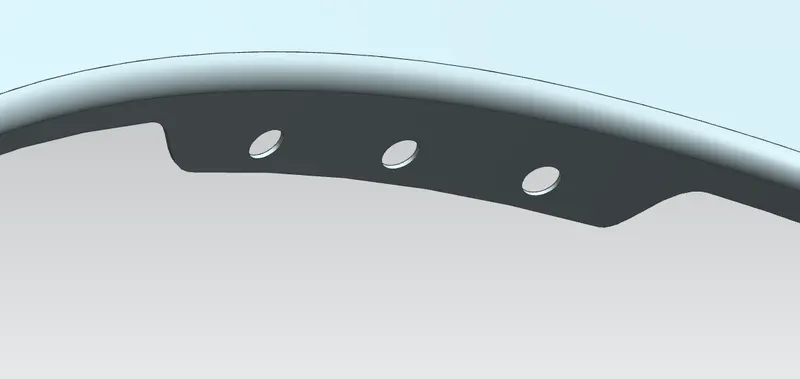
Figure.baffle mount2 Figure.baffle mount1
final fender.
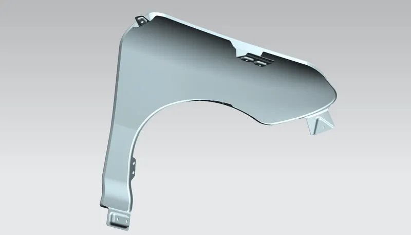
Figure.fender
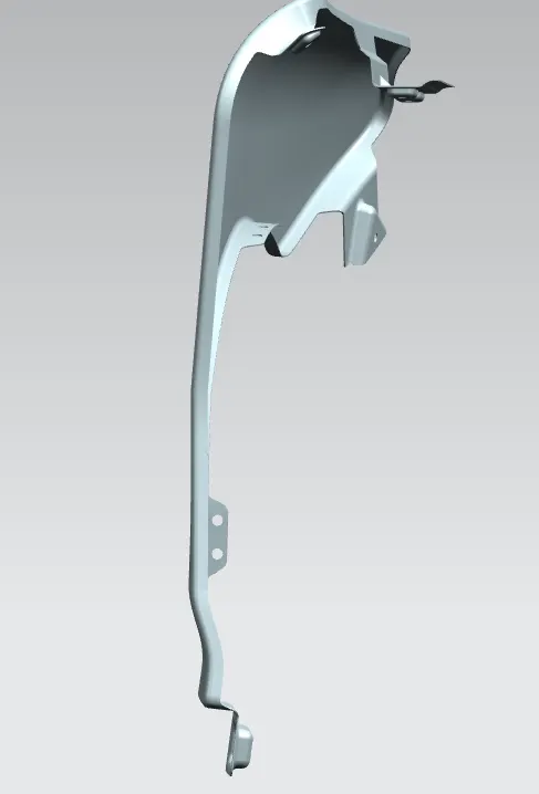
Figure.fender
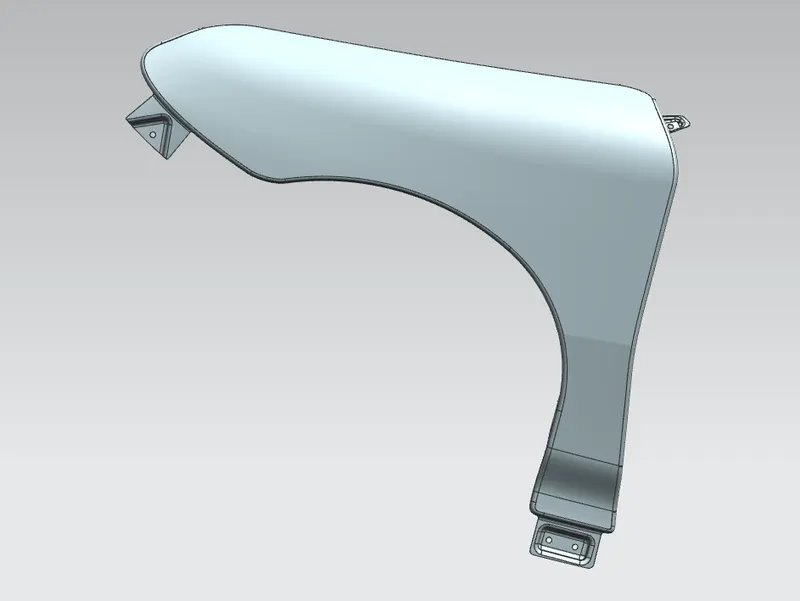
Figure.fender
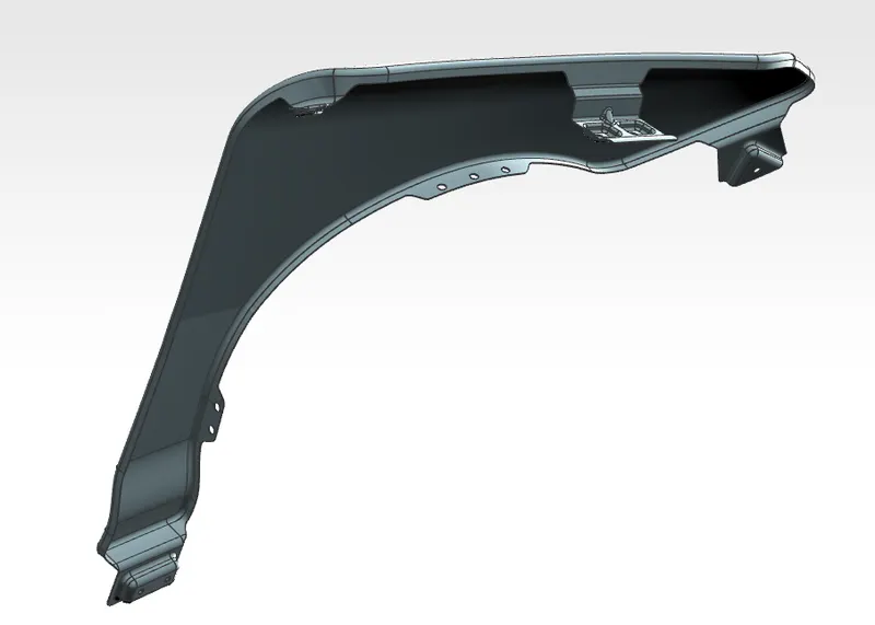
Figure.fender
Conclusion:_
The Fender is designed with the necessary mounting points considering the design parameters.