Fender Design
FENDER DESIGN
AIM
To design Dip area and mountings in fender by using given master section data.
FENDER
Fender is a metal or plastic enclosure over the wheels of an automobile or other vehicle to protect against splashing mud, etc.
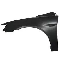
Importance of fender
Car fenders provide safety to the driver and the passengers at the time of accidents or collisions. They are manufactured in a way to provide bend during front and side collisions. Car fenders are designed to avoid wind resistance and make your car more aerodynamic. Car fenders enhance the overall look of your car.
TYPES OF FENDERS
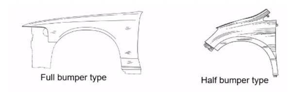
Full bumper type
The full bumper type model is used in the olden days this creates much wastage of material and the unnecessary cost is increased.
Half bumper type
This half bumper type is used for mainly cost and material cutting purpose as this type is also provides ease of manufacturing and the strength is also improved for half bumper type fender.
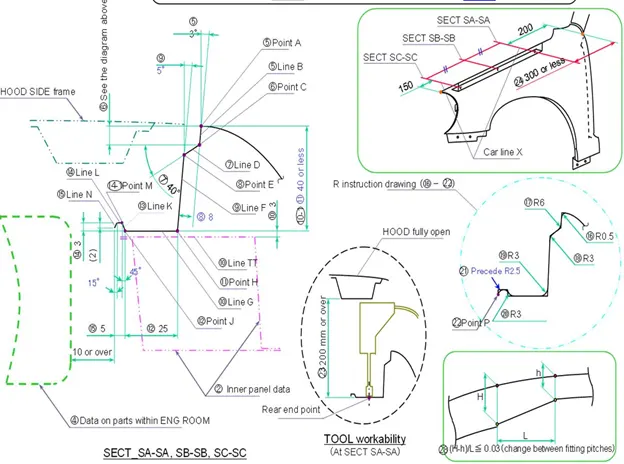
Master Section
MANUFACTURING PROCESS
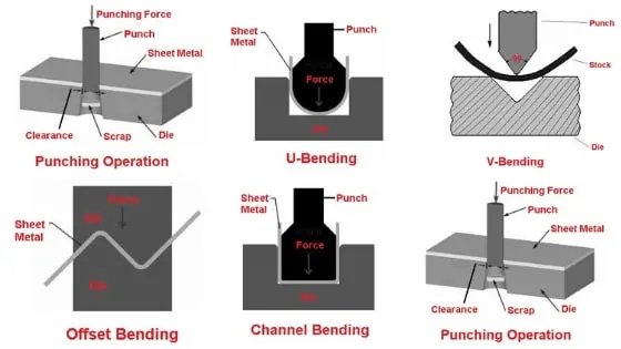
The manufacturing process includes the following steps that firstly, unfolding and shearing are carried out on a plate, wherein a proper cold roll specification is selected at first, a cold roll is unfolded, and then the unfolded cold roll is sheared to an iron plate of the corresponding size according to productio
A manufacturing process for automobile fender, comprises the following steps:
Step1: open straight snips plate: first select applicable cold coiling specification, cold coiling is opened flat; Then according to production material specification, will open cold coiling after flat and be cut into the iron plate of corresponding size; Finally, the iron plate after shear is cleaned to iron filings;
Step2: oil pressure, punch press: first iron plate is extended; Secondly to its trimming and punching; Then to its flanging and shaping; Finally, after shaping completes, then carry out one-off hole-piercing; Completed the making of lappet plate body;
Step3: the 1# smallclothes of processing lappet: first iron plate is stamped out to required outline blank (blanking); Then to completing the further moulding of iron plate of outline blank; Finally, it is carried out to punching;
Step4: panel beating assembly welding: first 1# small clothes are carried out to spot welding M6 nut; Then 1# part point is welded on lappet; Finally lappet body and 1# smallclothes are carried out to sanding thorn and ending.
DESIGN CONSIDERATION FOR FENDER
- Embosses are provided to increase strength.
- The corners of the flanges are smoothened to ease the producibility of part.
- Fillet of 2-3mm is provided to avoid sharp corners and edges.
- Cut outs are provided at certain regions in order to save material as possible.
- Rear clearance of drip area must be 200 mm from the cowl area.
- Frontal clearance of the drip area must be 150mm from the head light room.
- Always maintain 3degree angle to avoid human eye see the ugly component inside the hood.
- The total drip area length from the vertical must be always maintained below 40 mm to avoid the spring back effect The total drip area length from the vertical must be always maintained below 40 mm to avoid the spring back effect.
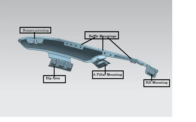
Fender technically has 5 major mounting points, they are;
1. A-pillar mounting.
2. Sill mounting.
3. baffle or splash mounting.
4. bumper mounting.
5. Drip area mounting.
A-PILLAR MOUNTING
- This Mounting region is also called as body mounting located near the cowl of the vehicle where the fender is fastened with the bottom edge of the windshield. This mounting is covered with the side rear-view mirror.
SILL MOUNTING
- The area at which the bottom of the fender gets connected to the floor near the bottom edge of the door. The Embossed sill mounting of the fender is attached with the fasteners.
BAFFLE OR SPLASH MOUNTING AREA
- In this region, the baffle gets installed to the fender with the help of clips which holds the baffle with the fender along the wheel arch.
- The flange provided for the wheel arch is provided with just holes for push pin clips to mount wheel arch.
- The mounting structure can ensure the strength and rigidity of an A post area of the fender, prevent local collapse, avoid abnormal sound produced by resonance due to poor rigidity and improve the NVH performance.
BUMPER MOUNTING AREA
- The bumper mounting region is located beneath the bumper. The fender gets attached before the installation of the bumper. After fixing the fender with fasteners the bumper will cover the bumper mounting.
DRIP AREA MOUNTING
- The area at which the fender gets attached to the engine housing through fasteners. It is the major mounting for the fender. Mountings at the drip area are designed leaving a clearance of 200mm from the back of the fender for the cowl setup. And clearance of 150mm from the front of the fender for a headlamp housing unit. Darts are provided at the bends to stiffen the sheet metal at that region.
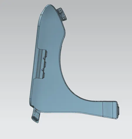
Different Views of fender
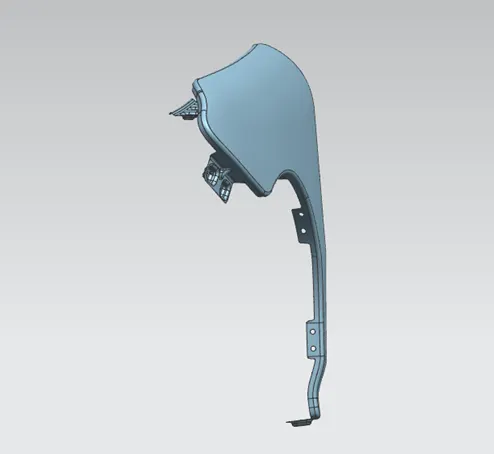
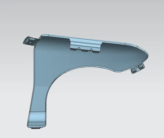
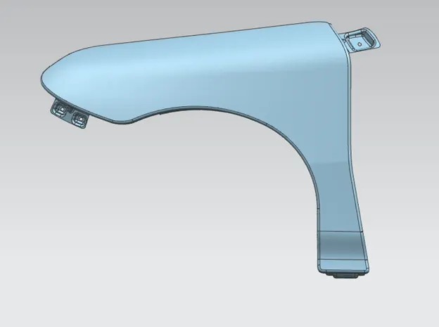
Conclusion:
Hence the Dip area and mountings has been designed in fender as master section provided under fender design criteria and sheet metal criteria