Fender Design
AIM: To design the Front fender from the given skin data by following the design rules and Master section.
INTRODUCTION :
Design of any product starts from an requirement . The design engineer sketches the product based on the the requirement . Then the 2D sketch with the proper dimensions is converted into the 3D model using the advanced CAD software's . The another important thing in the design is that , every product that is designed should be able to manufactured . so the role of the design engineer is to design the product that can be easily manufactured and with less cost effective . This is the place where the Design for manufacturing [DFM] and Design of assembly [DFA] takes a role while developing any product . The process of development of design carries on until the design satisfies the customer needs .Here in this project the product that we are going to develop is a car fender
Fender
- Fender is a protective covering of an automobile which covers the wheel and avoids the road spray from the wheel towards air, pedestrian, and other vehicles.
- For designing a fender we need to follow the design rules, these rules are explained in detail below.
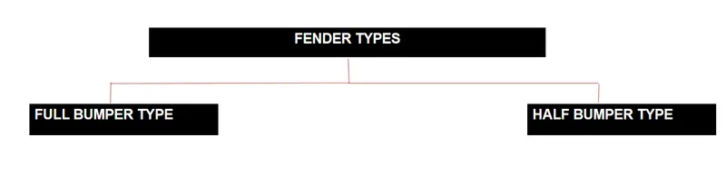
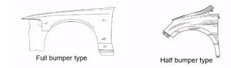
- Basically there are two types of fender they are Full bumper type and half bumper type. Nowadays most of the cars are having half bumper only for cost savings. Old vehicles are having full bumper type. It is shown in the below image.
-
TYPES OF FENDERS :
Full Bumper Type :
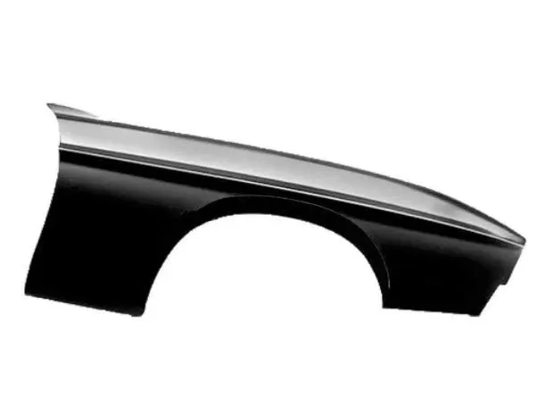
This type of bumper is not commonly used because this design is more scrap producing one during manufacturing. The blank of steel or aluminum usedto produce this type has more wastages. This type is not economically good to manufacture.
Half Bumper type :
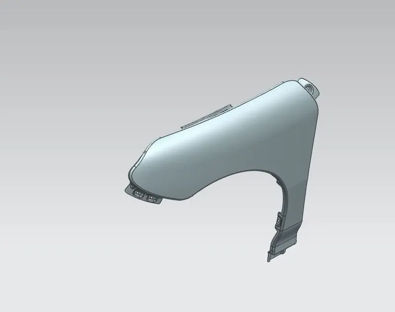
This types of fenders most commonly used. The con's of full bumper type is satisfied in this design, and the blank area of wastage while producing the part is drastically reduced by scrap management.
Purpoes of Fender :
Cleanliness : Protect the car, occupants and passers by from items, water, mud, snow, ice, thrown off the tires as you drive.
Safety : Protects pedestrain from the wheel, e.g. its better to be it by a laterally moving fender than a rolling tire, keeps loose, streaming items from being wrapped up in a rolling wheel.
Aerodynamics : Smooths the car profile so you don't get a lot of drag off the uncovered wheels. Some fenders are enclosed on the side for this.
General Appearance : Looks better with fender, gives a finished look, looks more streamlined.
Front Fender Desing :
The given master section to create the drip area and for the still mount, Bumper mount and A-pillar mount create your own design according to the engineering standard.
- Drip Area
- Sill Mount
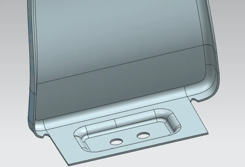
- Bumper Mount
- A Pillar Mount
- Splash/Baffle Mount
The Importance of car Fenders :
- The fenders are an intricate sheet of metal covering the wheel well of your car.
- Fenders are designed in a manner to provide resistance against wind and other roadside debris.
- When you travel on rough terrains tour vehicle might get minor scratches and dents which look no better. Frequent road bumps can cause your cars paint to chip off which needs a paint job done.
- The car fender are located on either side of the front and rear wheels. The front car fenders begin where the front door hinges run and end just before the bumper. The rear car fenders begin where the back doors close and terminate before the back bumpers.
For mounting point of view we always have 5 mounting points in a Fender they are
- Body
- A pillar
- Sill
- Cowl
- Drip
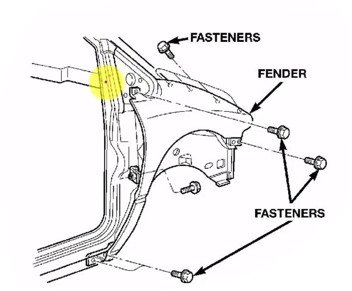
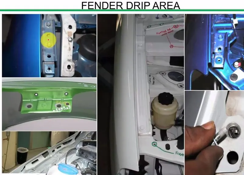
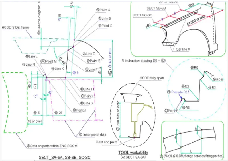
- From the above design requirements, the Drip area is the most important area for designing the fender. For fender drip area we are having various regulations to design for the pedestrian safety and for easy fixation of the fender with the engine compartment of the vehicle. It is shown below.
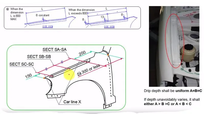
- The fender drip area always should have the following clearances for the ,ounting purposes. From the viper motor mounting region the fender should atleast have 200mm clearance then only the mounting of the fender by the use of the power tools also will be easy. It is shown below.
- The 200mm gap maintained from the one end of the fender will give the good tool workability for the fender while assembling it with the help of power tools. It is shown below.
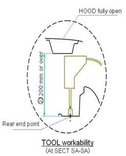
In the above image the rear end point specifies the end point of the fender drip area.
- And the drip area should maintain atleast 150mm of gap from the head light mounting area. To make the clearance for the head light mounting provisions, and the drip sholud have atleast 10mm of clearance for not making any damage to the other inside components while installing the fender to the vehicle.
- Another design regulation is we should follow the master section of the fender provided, this master section is shown below and their purposes are given in the below image.
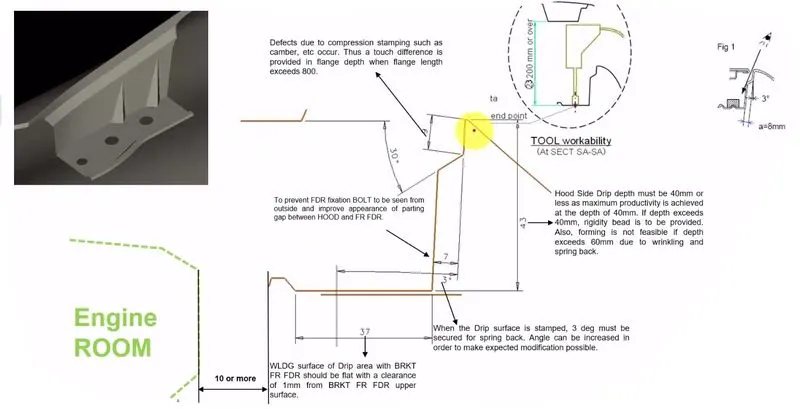
- Here we are following the inclination angle of 3 degree for making the flange to hide the inside bolting and fixation area when customer is seeing from the side of the car. And the flange should have a little opening angle from the fender surface to have a good manufacturability.
- The maximum length of the fender should not go beyond 60mm, if it goes beyon 60mm there will be some spring back effect, this will cause the fender drip area to deform its posistion after pressing or stamping process. So here in this design it is kept for 43mm.
- And the 10mm clearance gap is provided for the flange to the other components in the surronding of the fender in engine compartment area to avoid any collisions while assembling the components.
Side reference line
- Another important safety factor while designing the fender is side reference line. The can be explained from the below image,
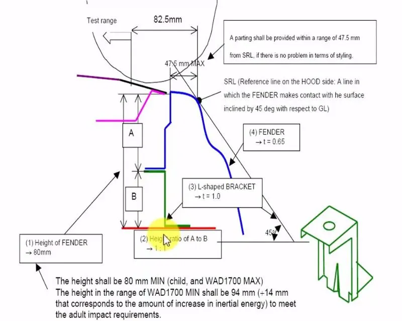
- In the above image the side reference line is shown, the side reference line is the line drawn for 45 degree from the ground level touching it to the fender.
- For the pedestrian safety the distace between the side reference line touching point with the fender to the edge of the fender should be lower than 47.5mm, the maximum value is 47.5mm it ahould not go above it, for the pedestrian and wrap around distance this value is maintained.
- If the skin data of the fender from the studio is not having this value we need to inform the styling team to make the change in the class A surface.
Fender wheel arch requirements
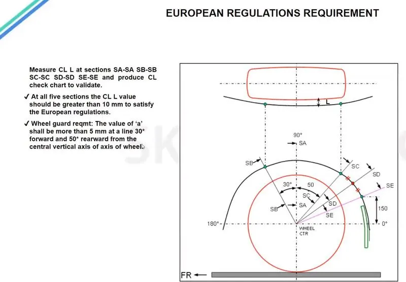
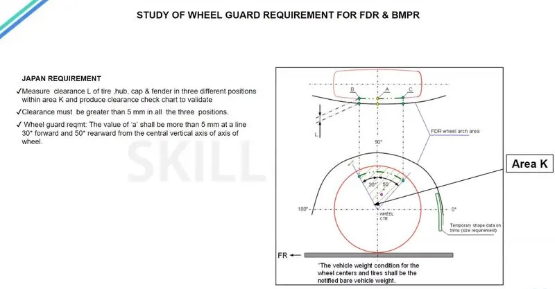
- There is some regulations followed for the fender wheel arch calculations if the class A skin of that wheel arch doesn't fulfill the requirements that fender sking data should be altered.
- There are various countries are following various regulations according to their road condition, here we can see for three countries such as Europe, Japan, US
- For European regulations the fender should pass the below requirements.
- For Japan regulations the fender should follow the below requirements
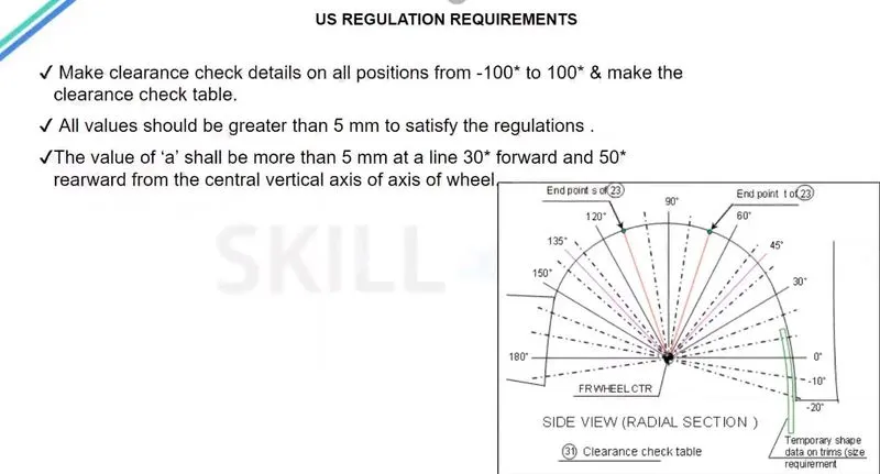
- For US road conditions the fender should follow the below rquirements.
DESIGN METHODOLOGY
GIVE DATA:
DESIGN OF DRIP AREA MOUNTING :
- It is the important uni of the fender. It is connected with the engine compartment , therefore the lot of design constraints are to be followed while designing the fender.
- While designing the drip we have to initially leave 200-300 mm for cowl top
- For placing the headlamp we have to leave at least 150 mm at the front while designing the fender
- Cowl top part consists pf wiper motor and its instruments.
DESIGN OF SILL MOUNTING AREA :
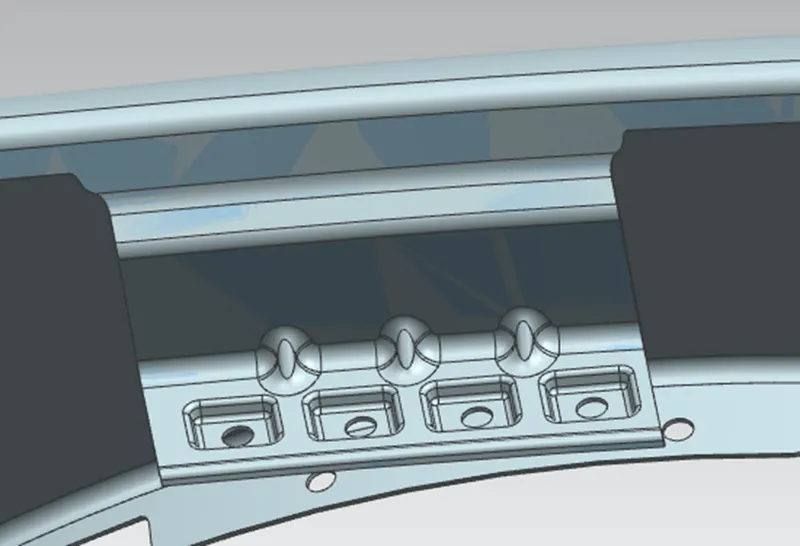
Sill is the panel directly below the bottom of the door supporting the floor and may be used to combine the floor and the body . the bottom end of the fender is mounting on the sill body for reinforcement of the fender panel ,thus the sill mounting position is designed with holes and emboss , M5 fasteners are used to fix the fenders on the sill body .
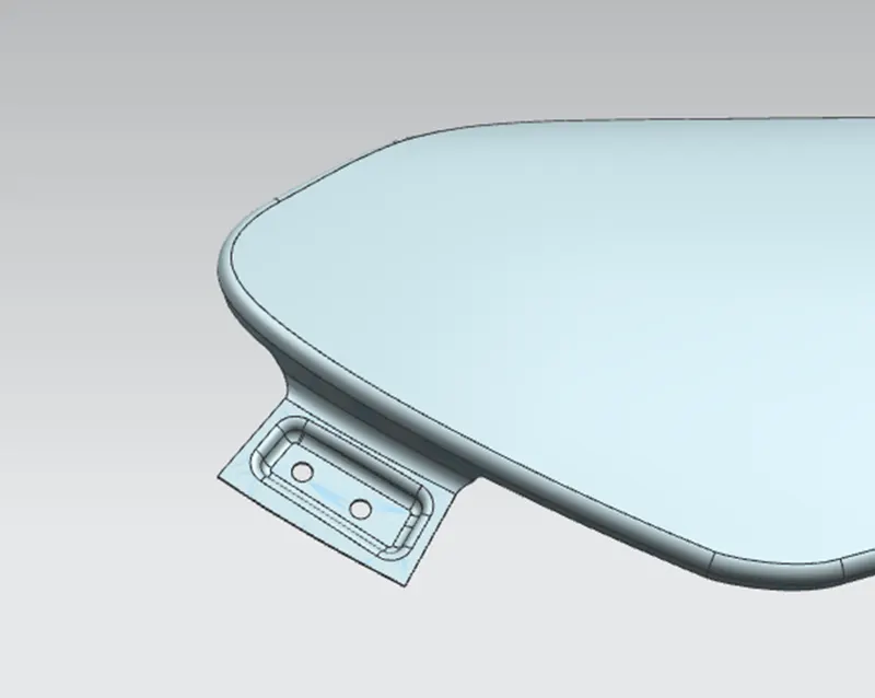
DESIGN OF BUMPER MOUNTING AREA:
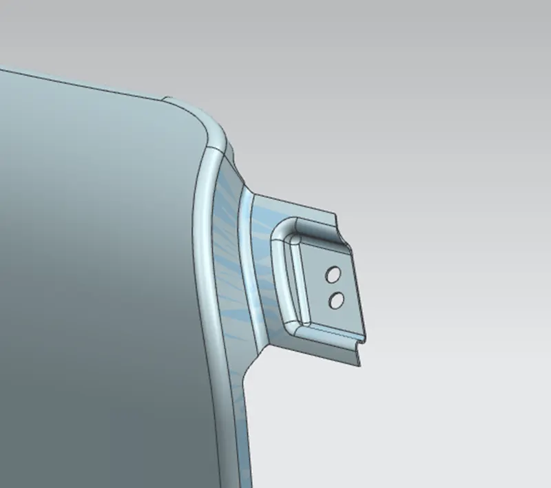
DESIGN OF A-PILLER MOUNTING AREA :
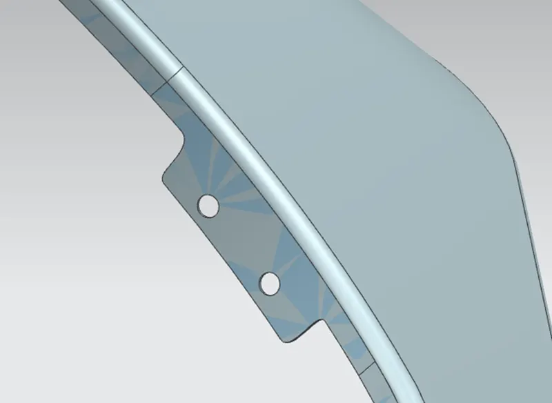
DESIGNOF BAFFLE MOUNTING AREA :
APPLYING OF THICKNESS TO THE SURFACE:
The thickness of 0.75mm inward on the final sewed surface of the fender to the sheet metal parameters
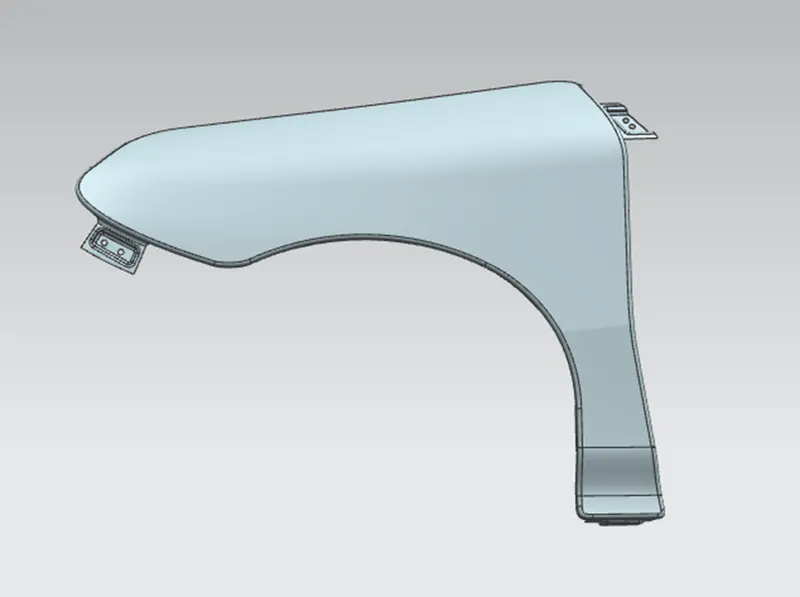
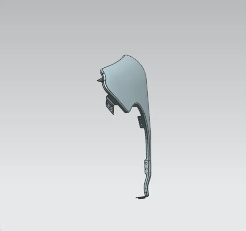
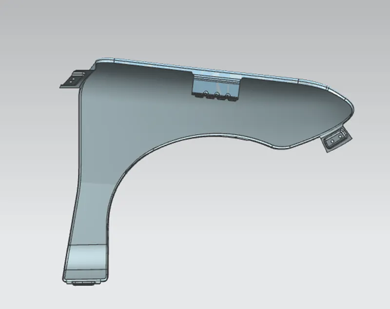
DIFFERENT VIEWS OF FENDER :
CONCLUSION :
Finally design of fender is done with the help of NX-CAD software by following the master section .