Exhaust Port Challenge
Conjugate Heat Transfer
Conjugate heat transfer corresponds with the combination of heat transfer in solids and heat transfer in fluids. In solids, conduction often dominates whereas in fluids, convection usually dominates. Conjugate heat transfer is observed in many situations. For example, heat sinks are optimized to combine heat transfer by conduction in the heat sink with the convection in the surrounding fluid.Conjugate heat transfer helps in finding heat fluxes and heat transferrates accurately in non uniform heat transfer cases and also where is becomes difficult to calculate using empirical formulaes.Heat transfer in solids and heat transfer in fluids are combined in the majority of applications. This is because fluids flow around solids or between solid walls, and because solids are usually immersed in a fluid. An accurate description of heat transfer modes, material properties, flow regimes, and geometrical configurations enables the analysis of temperature fields and heat transfer. Such a description is also the starting point for a numerical simulation that can be used to predict conjugate heat transfer effects or to test different configurations in order, for example, to improve thermal performances of a given application.
The Conjugate Heat Transfer (CHT) analysis type allows for the simulation of heat transfer between solid and fluid domains by exchanging thermal energy at the interfaces between them. Typical applications of this analysis type exist as, but are not limited to, the simulation of heat exchangers, cooling of electronic equipment, and general-purpose cooling and heating systems.
Baseline simulation:
Geometry is prepared according to the simuation requirements ,extra edges have been removed, solid and fluid volumes have been created and topology is shared between them for appropriate flow of information between the two volumes.
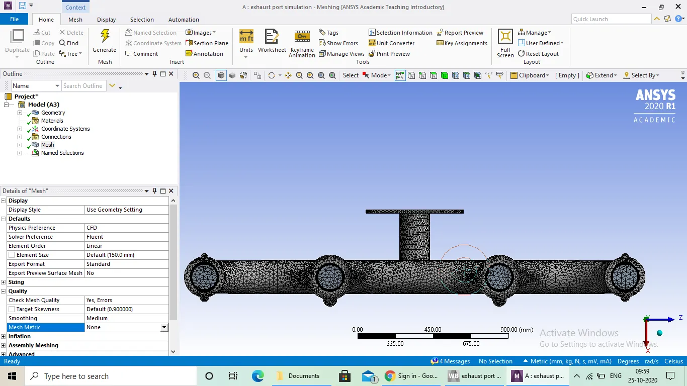
Mesh: Basic mesh is used which is generated by system and no refinement has been done.
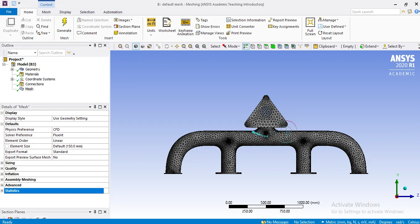
Setup: Coupled solver is used which is system default for the model ,turbulance model k-omega sst is used for both the cases and proper boundary conditions are specified remaining setup for both the cases are same.
solution: Calculation has been done until residulas have fallen below an acceptable range temperature contours are captured.
Result:
Visualization of temperature, velocity and heat transfer coefficient has been done with the help of contours which are given below
Outer Wall temerature distribution :
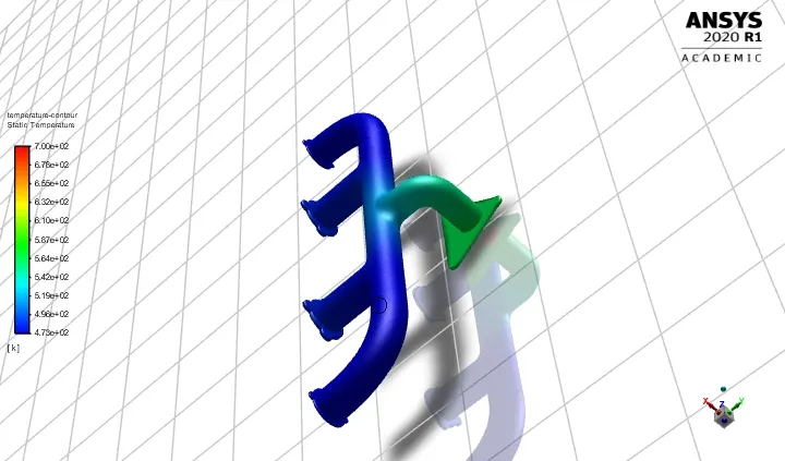
Maximum temperature reached is around 600k for outer wall and fluid has a maximum temperature of 700k which can be seen in the above contour.
fluid and innner wall Temperature :
velocity of fluid :
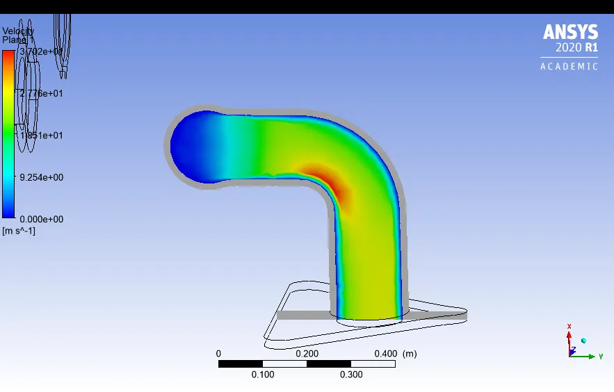
maximum velocity reached is 37.02 m/s which is at bend section of outlet pipe due to higher density and higher mass flow rate.
Heat transfer coefficient:
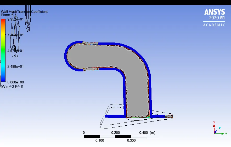
Maximum HTC achieved is 99.52 w/m^2 k, as no local refinement has bee done to model and no inflation layers are added, contour is coarse.As there will be no heat transfer coefficient for solids outer wall of the outlet manifold hence the value is zero whic can be observed from the contour.
Simulation 2:
Refined mesh :
Inflation layers are added to the model to capture the effects near the wall accurately and to obatin smooth and fine contours like Heat transfer coefficient contour.Sizing of outer solid volume is done with element size 8mm and allowing capture curvature to on.
Outer wall temperature contour:
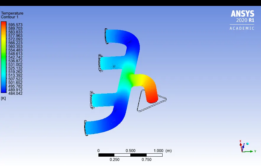
Maximum temperature achieved is 595.5k, at the end of outlet manifold where density of gases are high and minnimum temperature is 484k.
velocity contour:
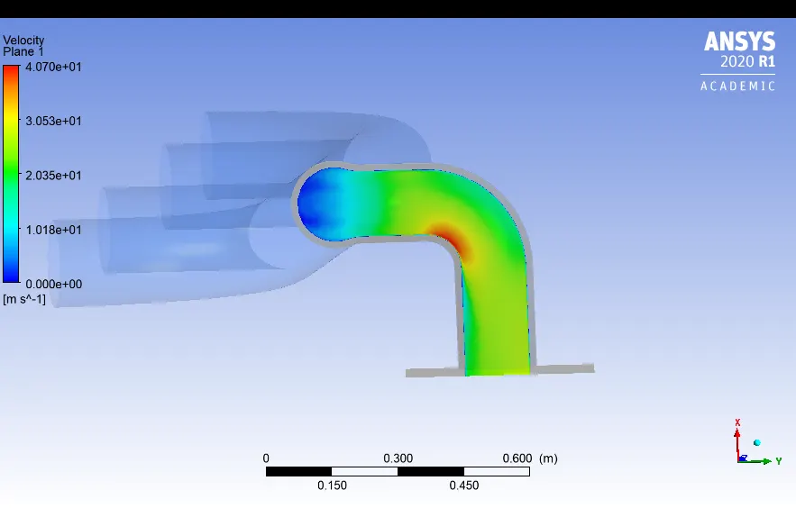
Maximum velocity is 40.7m/s which has a slightly greater than base line solution , at the entrance of the outlet manifold the velocity is very less as flow from all the inlet manifolds converge due to high pressures and large area velocity is less.
Heat transfer coefficient:
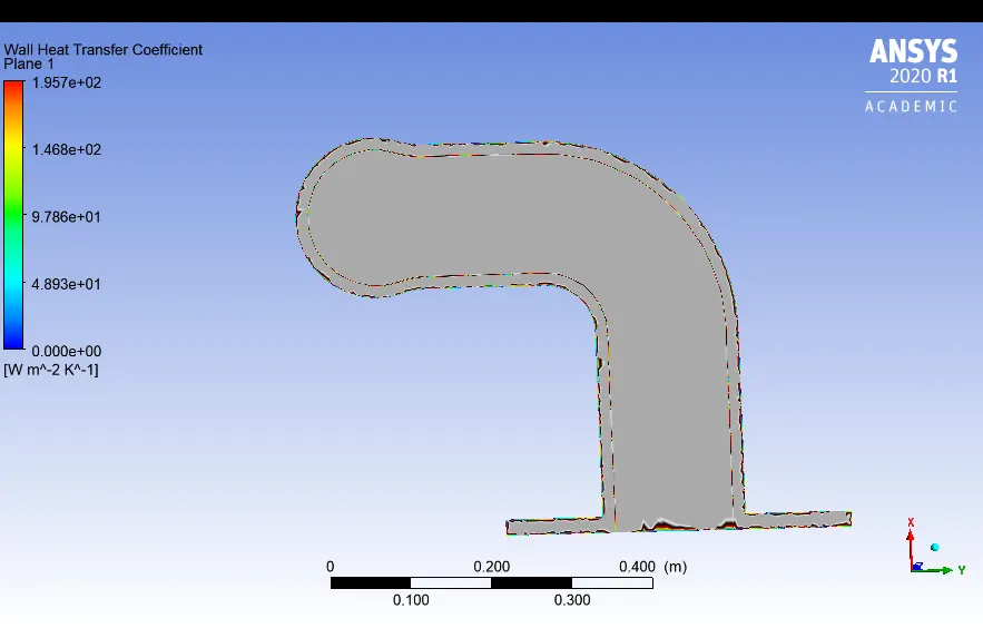
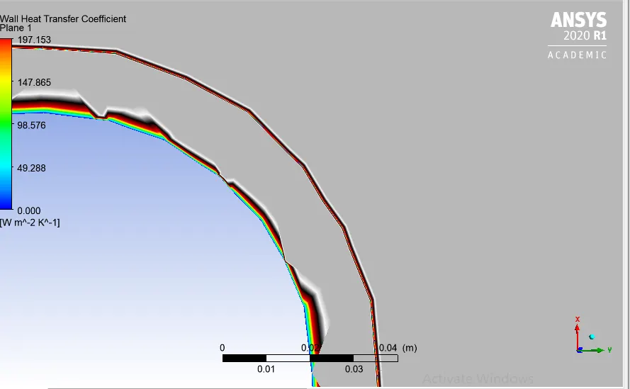
Maximum heat transfer coefficient achieved is 195.7 which is very high when compared it with baseline setup as inflation layer is added only cell near to the wall is captured and smooth contours are achieved.
Theoritical verification of Predicted HTC from the simulation results:
According to Bernoulli's mass conservation principle mass is conserved in our model which is clearly explained below.
Let us assume flow rate form each inlets as Q1,Q2,Q3,Q4 respectively and Q5 be the flow rate(out flow) from the exhaust manifold .
As mass in neither created nor destroted , mass flow rates are also balanced as below
`Q1+Q2+Q3+Q4=Q5`-------(1)`
we have `Q=rho.A.V`--------(2)`
now the equation 1 becomes
`A1.V1+A2.V2+A3.V3+A4.V4=A5.V5`
as it is uncompressible flow to compensate the mass flow, velocity is incresed and overall mass flow rate is conserved.
As velocities are high, reynolds number at outlet manifold will be high.
Nu=f(Re, pr) for froced convection applictaions,
`Nu=(h.L)/k`
from the above eqauions
`NupropRe`,`Nuproph`,
hence `Re prop h`
From our simulations we have observed velocities are high at bend section of outlet manifold hence higher reynolds number which has high Heat transfer coefficients.
Therefore predictions from our simulations can be considered as correct.
Factors influence accuracy of prediction:
1) Mesh quality greatly impacts the accuracy of predicted value from our simulations which can be observed from the above contours and maximum values of related parameters like velocity and heat transfer coefficient .
2) Appropriate y+ value which helps in calculating first layer thickness from the wall for the better capturing of effects near walls, which is HTC in our case.
2) Appropriate turbulance model have to be used in accordance with y+ value which is very important and K- omegha sst model is used in our case.
3)Appropriate solvers is one of the most important factor which leads all the calculations in solving the equations, First order Upwind coupled solver is used .