Emission characterization on a CAT3410 engine
ABSTRACT:
Diesel engines are common combustion engines which are used in automotive and aircraft industries. Due to its high compression ratio factor, the efficiency of these engines is comparatively higher than SI engine. For the present case study emission characteristics of CAT 3410 engine is studied and analysed using a bowl profile. Two different design of piston: open-w piston and omega piston are used to compare the emission and performance characterization. Sector profile modelling, Spray modelling, parcel simulation and embedded scaling are performed to compare the NOx, soot and UHC level of two different piston design.
AIM:
Emission characterization on a CAT3410 engine.
INTRODUCTION:
The diesel engine, named after Rudolf Diesel, is an internal combustion engine in which ignition of the fuel is caused by the elevated temperature of the air in the cylinder due to the mechanical compression (adiabatic compression); thus, the diesel engine is a so-called compression-ignition engine (CI engine). This contrasts with engines using spark plug-ignition of the air-fuel mixture, such as a petrol engine (gasoline engine) or a gas engine (using a gaseous fuel like natural gas or liquefied petroleum gas).
Diesel engines work by compressing only the air. This increases the air temperature inside the cylinder to such a high degree that atomised diesel fuel injected into the combustion chamber ignites spontaneously. With the fuel being injected into the air just before combustion, the dispersion of the fuel is uneven; this is called a heterogeneous air-fuel mixture. The torque a diesel engine produces is controlled by manipulating the air-fuel ratio (λ); instead of throttling the intake air, the diesel engine relies on altering the amount of fuel that is injected, and the air-fuel ratio is usually high.
The diesel engine has the highest thermal efficiency (engine efficiency) of any practical internal or external combustion engine due to its very high expansion ratio and inherent lean burn which enables heat dissipation by the excess air. A small efficiency loss is also avoided compared with non-direct-injection gasoline engines since unburned fuel is not present during valve overlap and therefore no fuel goes directly from the intake/injection to the exhaust. Low-speed diesel engines (as used in ships and other applications where overall engine weight is relatively unimportant) can reach effective efficiencies of up to 55%.
Diesel engines may be designed as either two-stroke or four-stroke cycles. They were originally used as a more efficient replacement for stationary steam engines. Since the 1910s, they have been used in submarines and ships. Use in locomotives, trucks, heavy equipment and electricity generation plants followed later. In the 1930s, they slowly began to be used in a few automobiles.
The characteristics of a diesel engine are
- Compression ignition: Due to almost adiabatic compression, the fuel ignites without any ignition-initiating apparatus such as spark plugs.
- Mixture formation inside the combustion chamber: Air and fuel are mixed in the combustion chamber and not in the inlet manifold.
- Torque adjustment solely by mixture quality: Instead of throttling the air-fuel mixture, the amount of torque produced is set solely by the mass of injected fuel, always mixed with as much air as possible.
- Heterogeneous air-fuel mixture: The dispersion of air and fuel in the combustion chamber is uneven.
- High air ratio: Due to always running on as much air as possible and not depending on exact mixture of air and fuel, diesel engines have an air-fuel ratio leaner than stochiometric
- Diffusion flame: At combustion, oxygen first has to diffuse into the flame, rather than having oxygen and fuel already mixed before combustion, which would result in a premixed flame.
- Fuel with high ignition performance: As diesel engines solely rely on compression ignition, fuel with high ignition performance (cetane rating) is ideal for proper engine operation, fuel with a good knocking resistance (octane rating), e.g. petrol, is suboptimal for diesel engines.
OBJECTIVES:
- Create cut-plan animations showing Soot, Nox and UHC and compare them between the omega and the open-w pistons.
- Compare the imep and power values graphically
- Make sure that the sector angle and periodic angle are 60°.
Modelling approach:
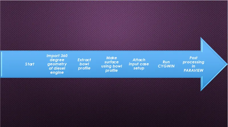
Geometrical creation of sector profile of Diesel engine
A complete design of 360 degree open-w piston is provided to us. Now using the complete diesel engine geometry, the time and computing power required to run the simulation will be too costly and high. So, to reduce the time and increase computational efficiency, we create a sector of the diesel engine profile.
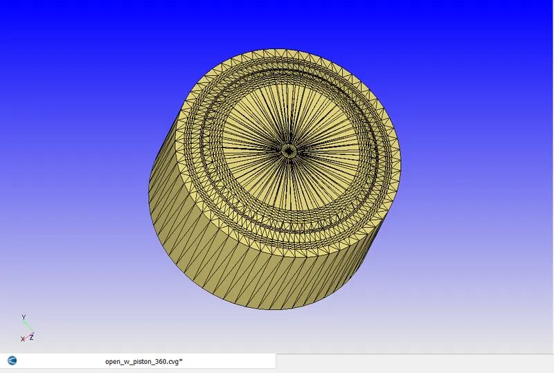
First, we import the 360-degree open-w piston geometry model by going to file>> open>>import surf.dat file> choose the 360-degree open-w piston profile.
We get the complete visual model of the bowl shape piston design.
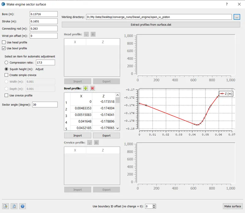
Now we have to make the sector profile shape of the geometry using make surface command.
Go to tools> select make engine sector surface.
Give all the engine parameter details as given below:
Bore=0.13716m
Stroke length=0.1651m
Connecting rod=0.263m
Sector angle=60 degree
Now select the option surface profile extract. On clicking select the surface,dat file which is already given as input.
Converge automatically creates bowl profile, forward profile, reverse profile and head profile.
Now to give a shape to the piston profile, check box the bowl profile option>> select the import option and choose the bowl profile.
The key difference between the extract surface and make surface is that in extract surface, only the surface of the bowl profile is extracted to create the shape. In make surface, not only the surface profile but also the geometrical design details of the piston are considered to create the piston shape in the converge studio panel.
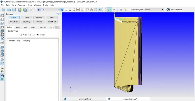
The same procedure is followed for omega piston. A separate file for the omega shape profile is provided.
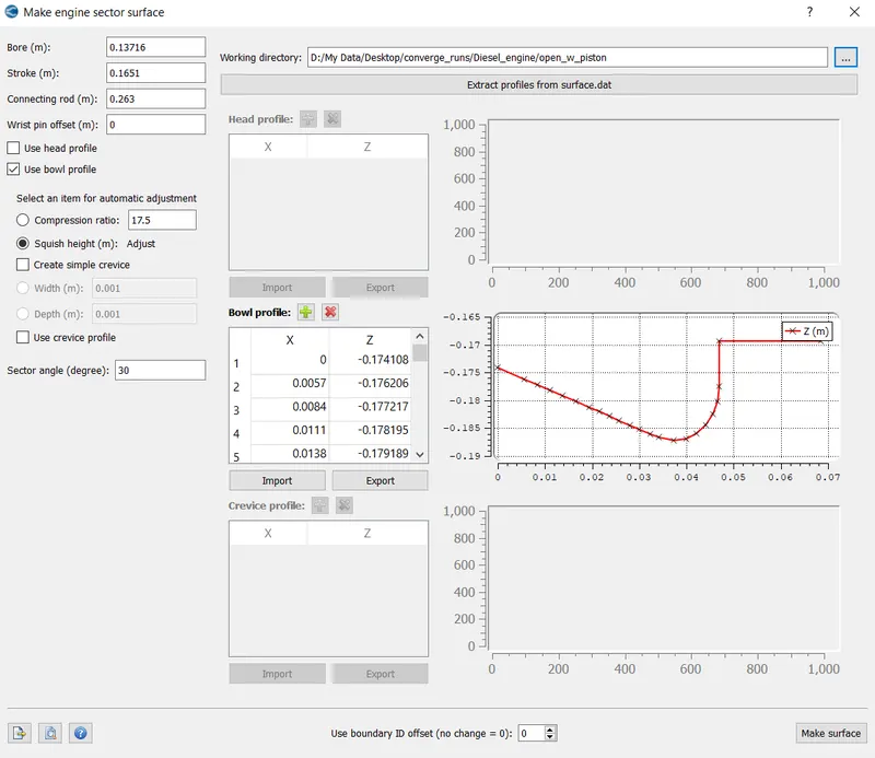
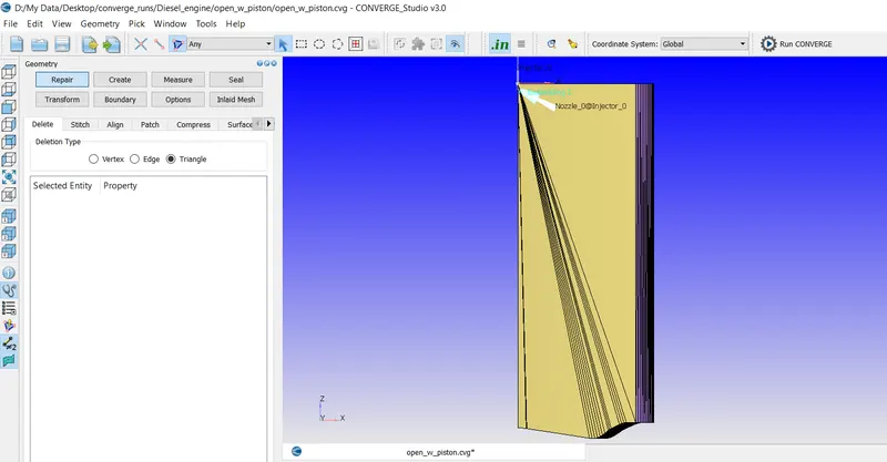
The final shape of the two-piston design is given below:
Open-w piston:
Omega piston:
Simulation case setup:
Application:
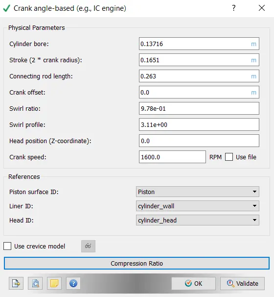
Type- crank angle based IC engine
Details of IC engine
Cylinder bore: 0.13716m
Stroke length: 0.1651m
Connecting rod: 0.263m
Crank speed: 1600rpm
Piston surface ID: piston
Liner ID: cylinder wall
Head ID: cylinder head
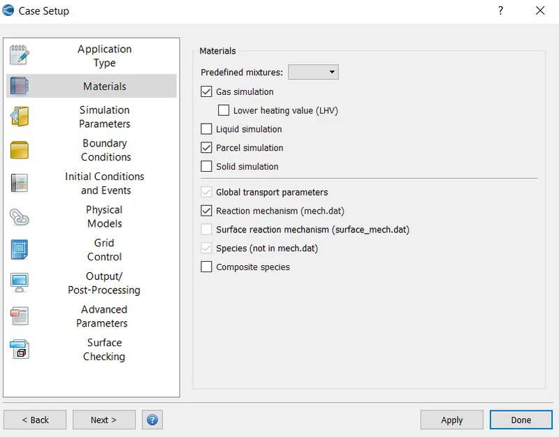
Materials:
Enable reaction mechanism option
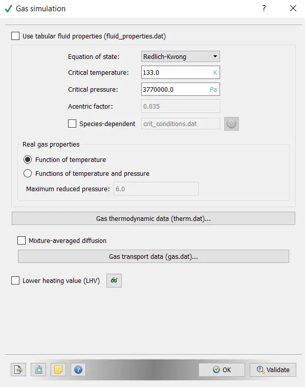
Gas simulation:
Select the gas thermodynamic data>> select import data from therm.dat>>load the therm.dat file
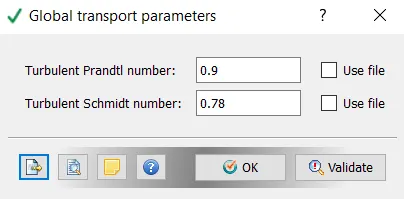
Global transport parameters:
Select default settings
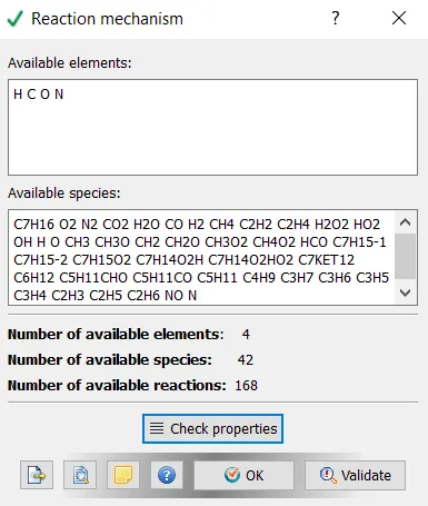
Reaction mechanism:
Select data from mech.dat file>> load the mech.dat file containing all the reacting species
Click on check properties. The following message will pop up ‘no errors found’
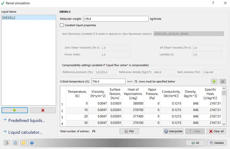
Parcel simulation:
Parcel refers to Lagrangian based spray model. Parcel undergoes several physical process like primary breakup, secondary breakup, drop drag, coalescence and collision, evaporation etc. parcel statistically determines the fuel spray.
Isooctane DIESEL2 is chosen as a parcel, which will act as a fuel medium for combustion.
Select Add option> choose DIESEL2> check validate and the ok
Simulation parameters:
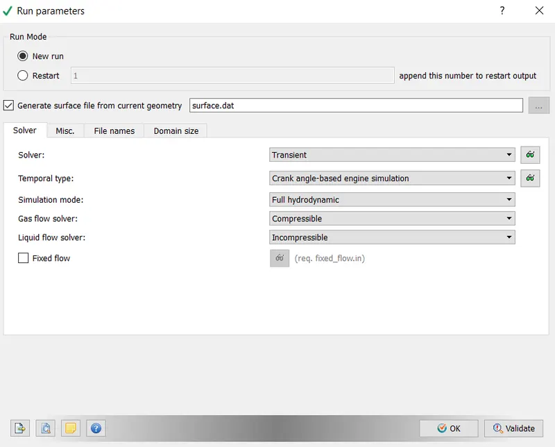
Run parameters:
Solver- transient
Temporal type- crank angle based engine simulation
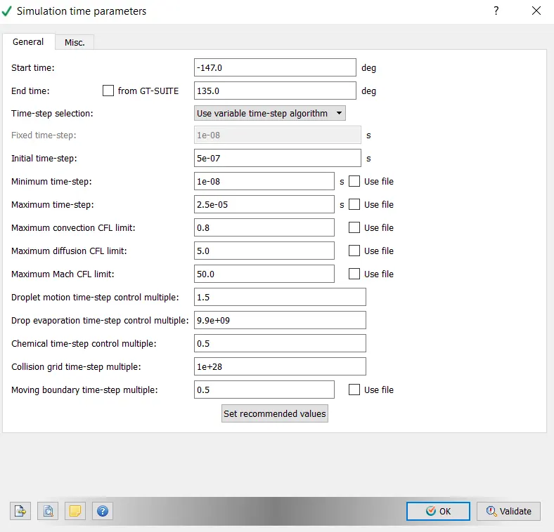
Simulation time parameter:
Start crank angle: -147 degree
End crank angle: 135 degree
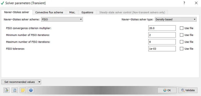
Solver parameter:
Navier-Stokes solver type: density based
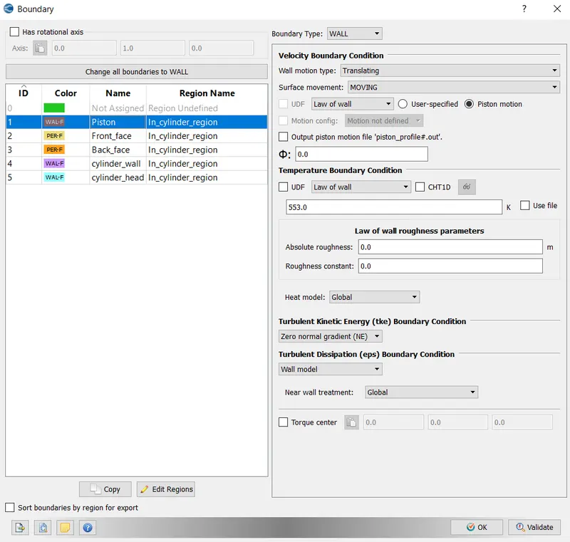
Boundary conditions:
Piston:
Boundary type- wall
Wall motion- translating, law of wall, piston motion
Temperature: 553k, law of wall
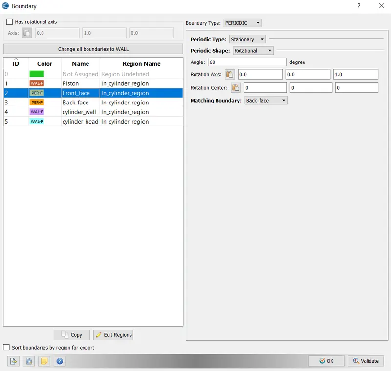
Front_face:
Boundary type: Periodic
Periodic type: Stationary
Periodic shape:Rotational
Angle: 60degree
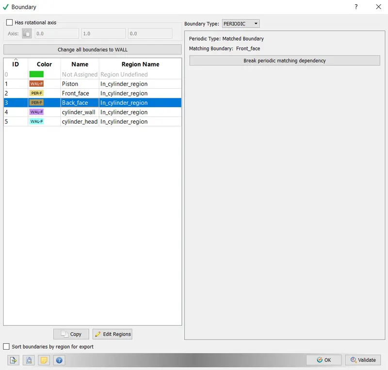
Back face:
Boundary type: Periodic
Periodic type: Matched boundary
Matching boundary: Front face
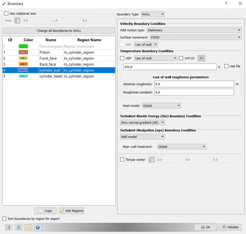
Liner:
Boundary type: wall
Wall motion: stationary, fixed, law of wall
Temperature: 433k, law of wall
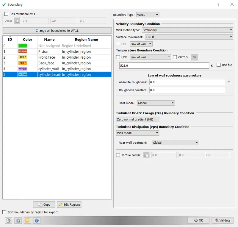
Cylinder head:
Boundary type: wall
Wall motion: stationary, fixed, law of wall
Temperature: 523k, law of wall
Initial conditions:
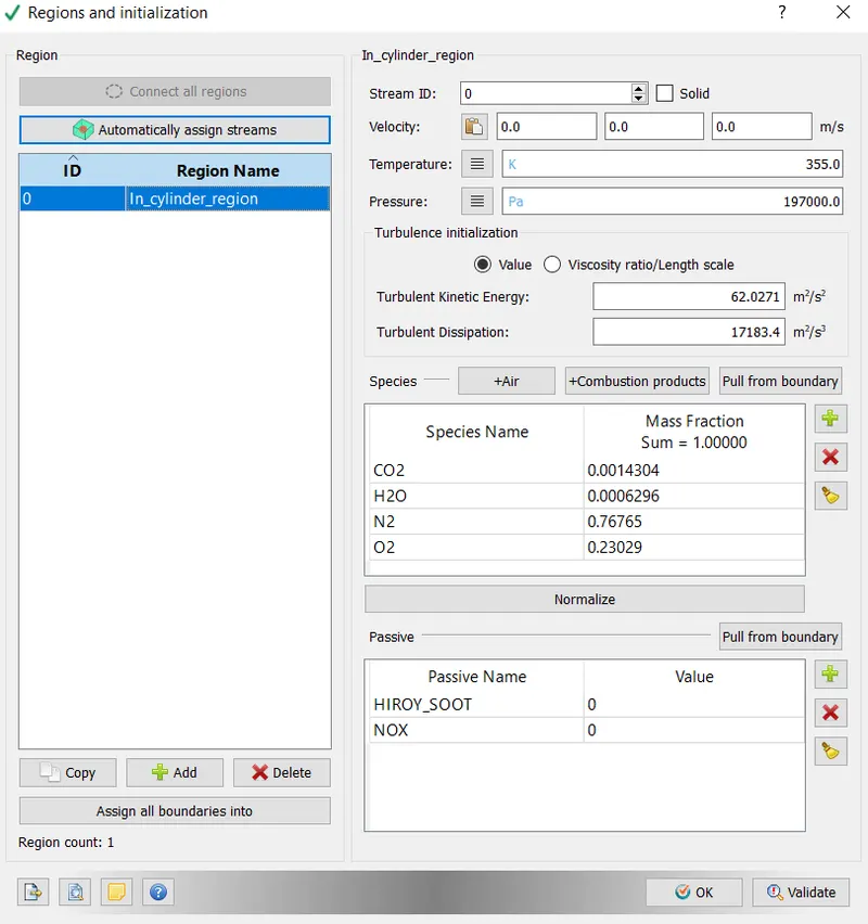
Region 0: In_cylinder region
Temperature-355k
Pressure-197000Pa
|
Species |
Mass fraction |
|
CO2 |
0.0014304 |
|
H2O |
0.0006296 |
|
N2 |
0.76765 |
|
O2 |
0.23029 |
Passives: Hiroy soot and Nox
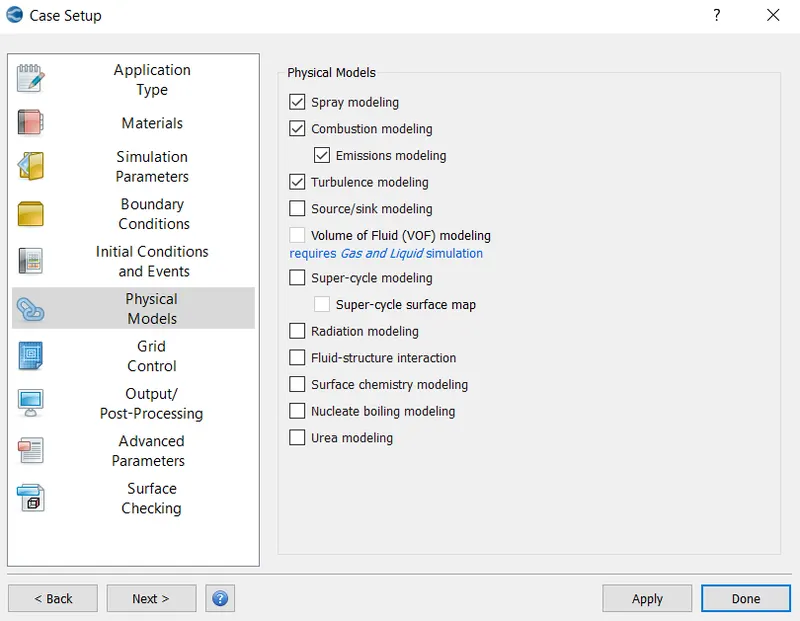
Physical model
Spray modelling:
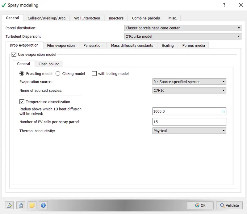
Spray modelling includes liquid atomization, drop breakup, collision, turbulent dispersion etc. in converge spray model of liquid droplet is done by lagrangian parcel method. In each drop of parcel, the mass, momentum, energy and heat transfer are solved. It is sometimes called discrete phase model or lagrangian model.
The general settings for the spray model is given below:
Parcel distribution: distribute parcel evenly throughout the cone
Turbulent dispersion: O’Rourke model
Drop evaporation> use evaporation model
Evaporation source: source all base parcel species
Enable temperature discretization
Radius above which ODE needs to be solved: 1000
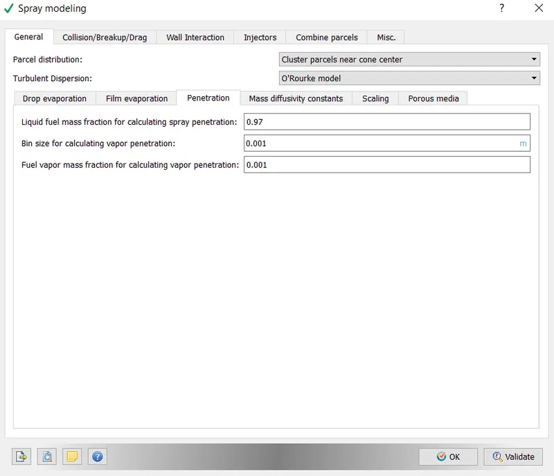
Spray penetration:
Set as default settings
Collision model:
Model: NTC Model
Drop and drag model > select dynamic drop and drag model
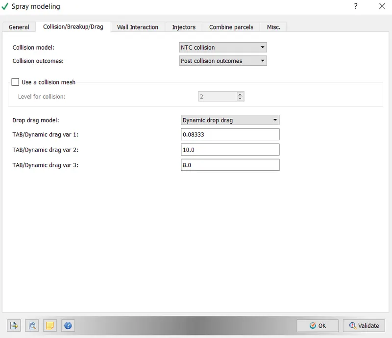
Injectors:
Now we define the inputs to the injector parts.
Go to injectors> select the edit tab
Injected species/ Rate shape
Select the parcel species as DIESEL2
Mass fraction: 1
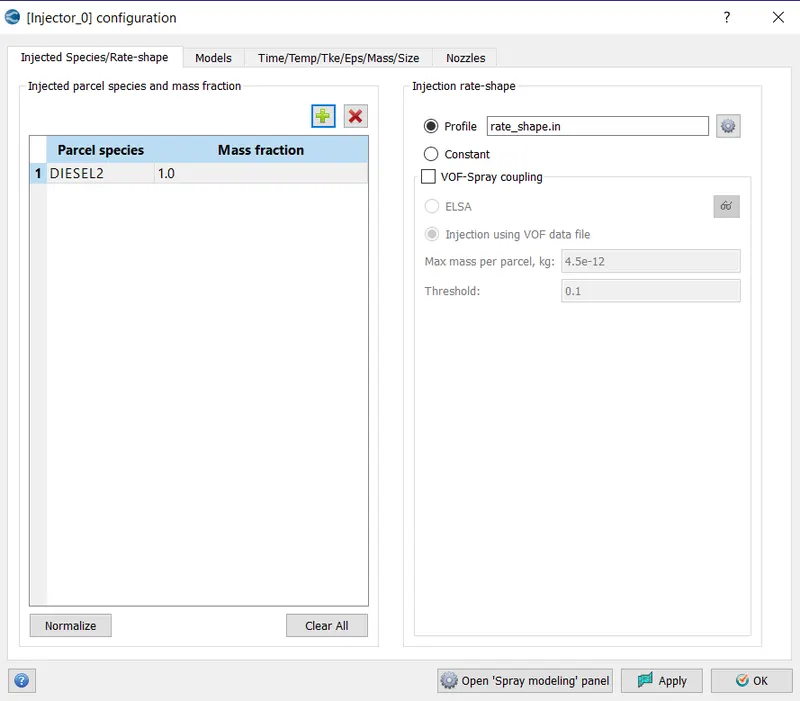
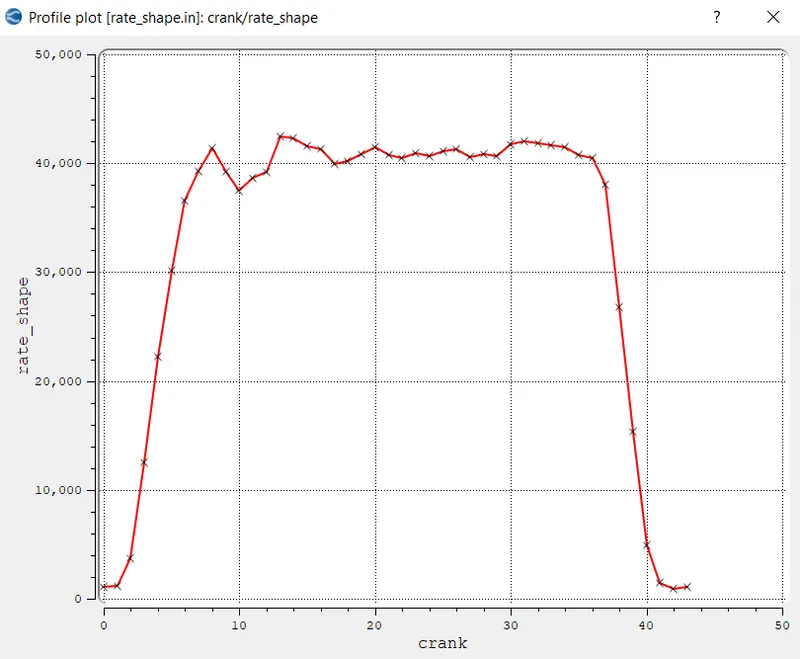
Injection rate shape:
We use the profile option to define the rate shape function with respect to the crank angle.
Save the file name as rate_shape.in format.
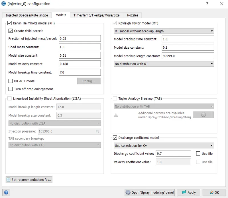
Models:
Activate the kelvin-Helmholtz model and Rayleigh-Taylor model.
Time/temp/TKE/EPS/Mass/Size:
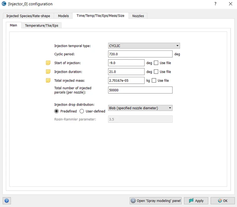
Go to the Main tab.
Injection temporal type: cyclic
Cyclic period: 720 degree
Start injection: -9 degree
Injection duration: 21 degree
Total injected mass: 2.701067e-5kg
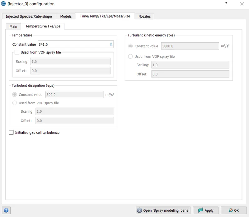
Temperature tab:
Temperature constant value: 330k
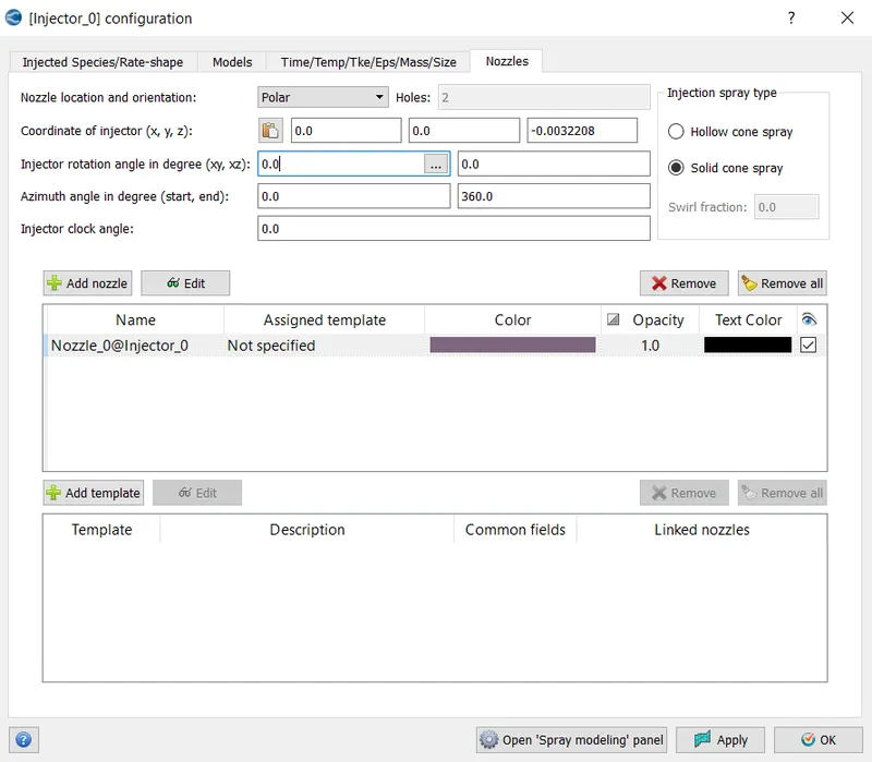
Nozzles:
We define the settings as given below.
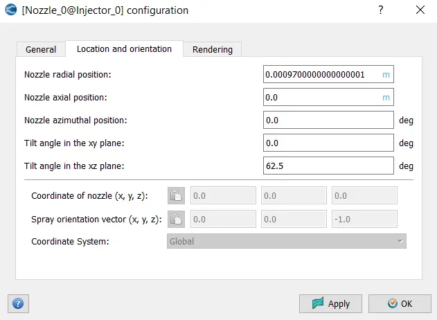
Nozzle location and orientation:polar
Click on the add nozzle tab and select the edit option.
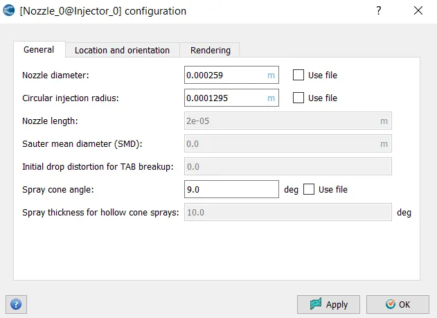
General tab
Injection nozzle 0
Nozzle diameter: 259e-6 m
Circular injection radius: 1295e-6 m
Spray cone angle: 9 degree
Provide the location coordinate of nozzle.
Provide the spray orientation axis of the nozzle.
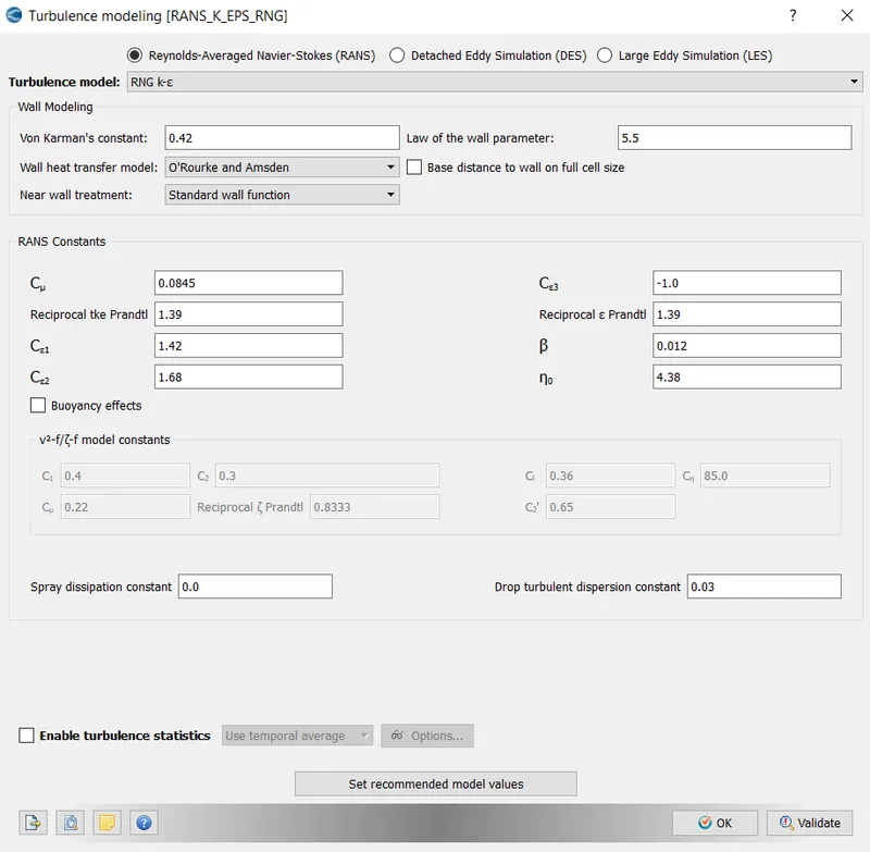
Turbulent model: RNG K-epsilon
Combustion modelling:
The combustion is modelled by the reaction mechanism. There are multiple intermediate species that govern the combustion reaction. The reaction mechanism is too large to simulate, so it is solved for those species whose presence are affected by combustion.
In combustion modelling SAGE chemistry solver is used. Some of the details regarding the solver is given below:
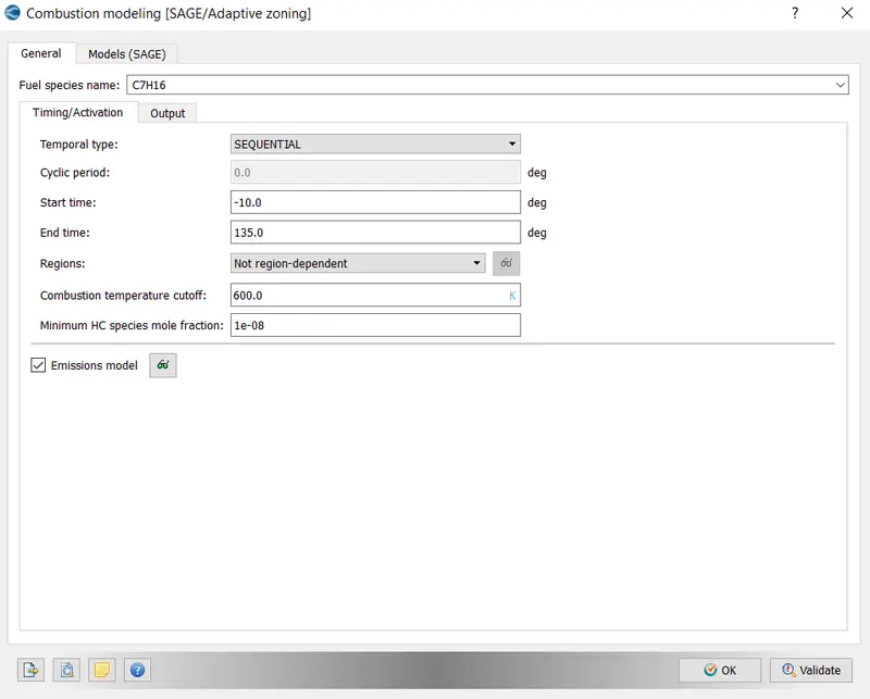
For General tab
Fuel species: C7H16
Temporal type: sequential
Cyclic period: 720 degree
Start:-10 degree
End: 135 degree
Combustion cut off temperature: 600k
Minimum HC species mole fraction: 1e-8
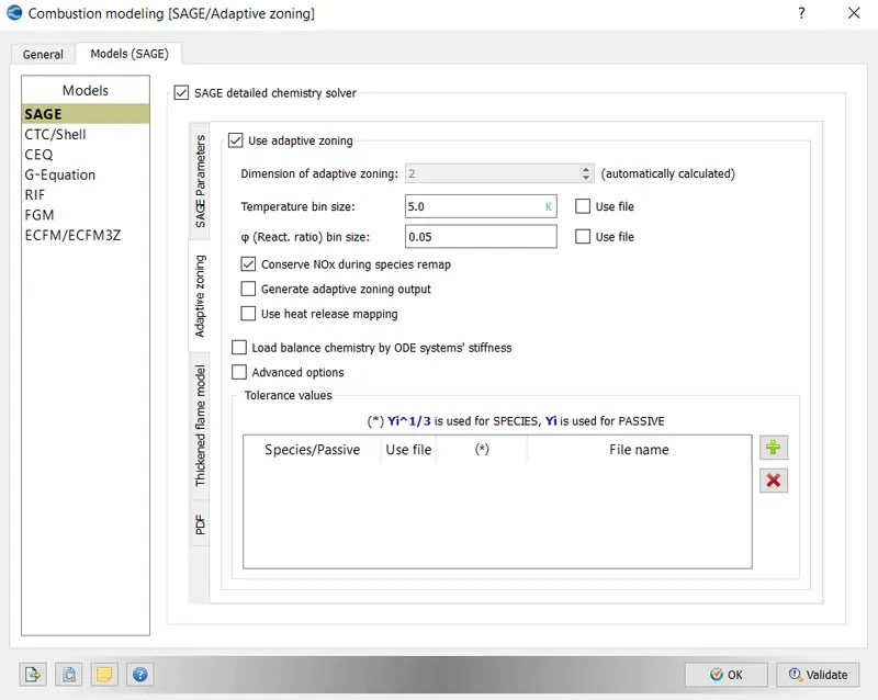
Model tab
Models: SAGE modelling
Adaptive zoning: This technique helps converge to quickly simulate the flow field by speeding up species transport equation and reach an accurate limited phenomenon and emission.
Emission modeling:
NOX model:
Check thermal nox model (zeldovich)
O/OH model for thermal nox: equilibrium
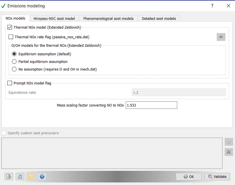
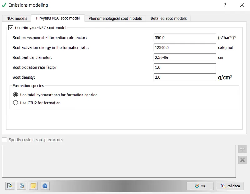
Hiroyasu soot model:
Soot pre mixed rate:350
Soot activation energy: 12500cal/gmol
Soot particle dia: 2.5e-6 cm
Soot oxide rate formation:1
Soot density:2gm/cm3
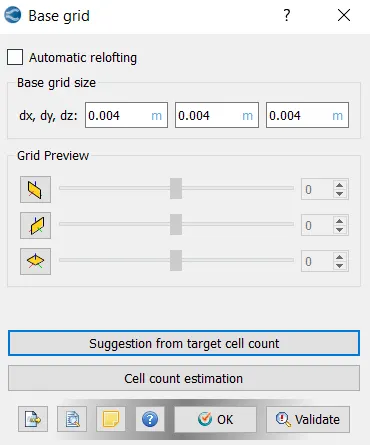
Grid control:
Base grid:
Choose base grid as 4mm
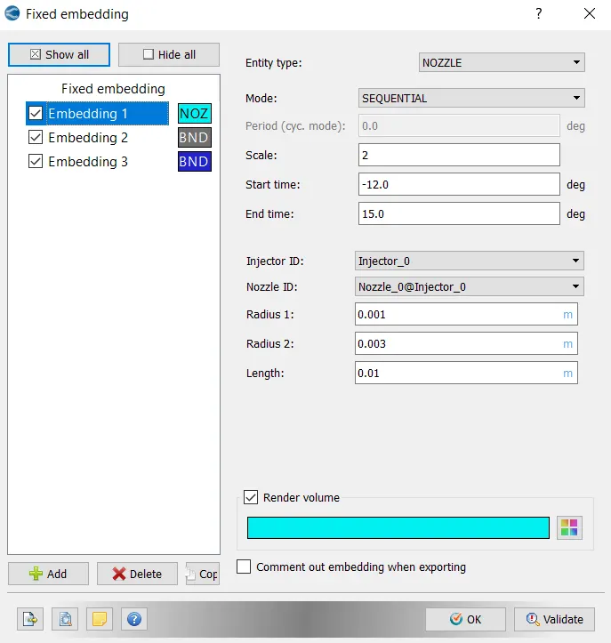
Fixed embedding:
Embedding is performed to refine the grid scale factor at different regions of geometry.
- Embedding 1
Fixed embedding are provided in the region of nozle.
Entity type: nozzle
Mode- sequential
InjectorID: injector_0
Scale- 2
Start time:-12 degree
End time:15 degree
Radius1:0.001m
Radius2:0.003m
length:0.01m
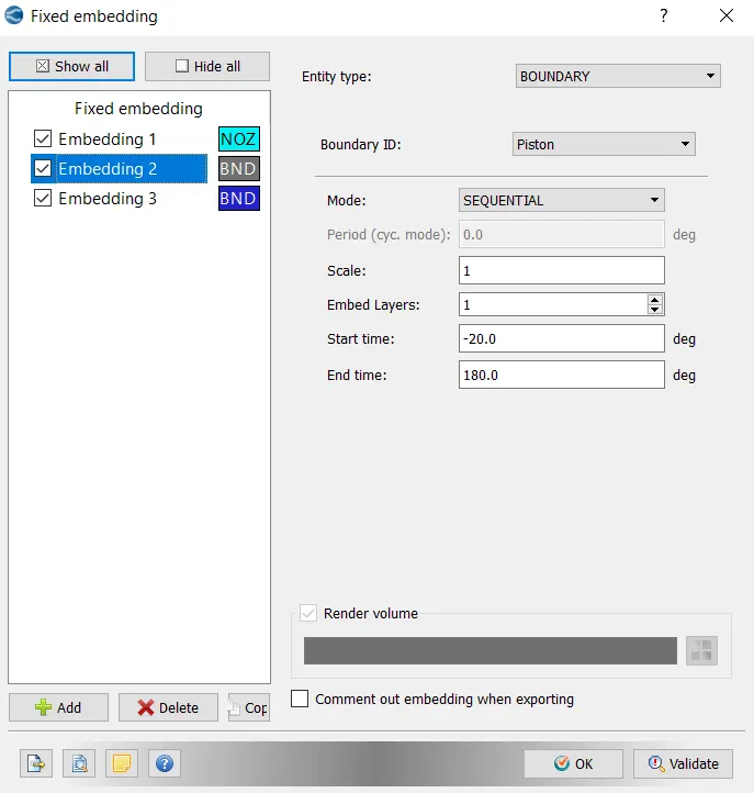
2. Embedding 2
Fixed embedding are provided in the region of piston.
Entity type: boundary
Mode- sequential
boundary ID:piston
Scale- 1
Embed layers:1
Start time:-20 degree
End time:180 degree
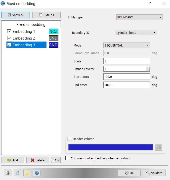
- Embedding 3
Fixed embedding are provided in the region of cylinder head.
Entity type: boundary
Mode- sequential
boundary ID:cylinder_head
Scale- 1
Embed layers:1
Start time:-20degree
End time: 180degree
Adaptive mesh refinement (AMR):
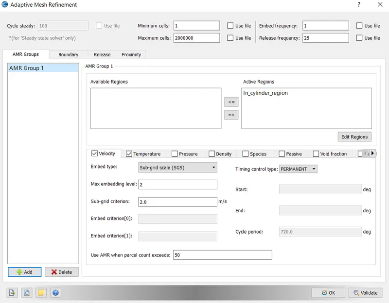
Fixed embedding is preferred at the regions of complete boundary area. When refinement has to be done on the regions of flow equations, the refinement is called adaptive mesh refinement. Sub grid scaling approach is used to scale down the refinement of mesh.
- Velocity AMR
The velocity AMR is kept constant, and is defined in the in_cylinder regions.
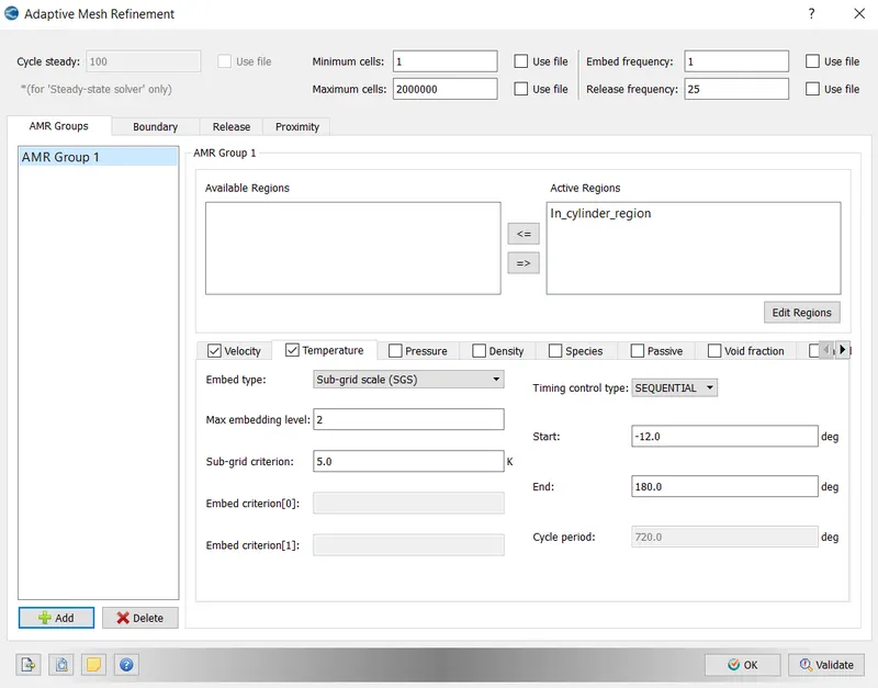
- Temperature AMR
The temperature AMR is defined in the in cylinder region.
Simulation run:
- Export all the case set up from the converge studio
- Go to Cygwin>> go to desired path or directory
- Type the command mpiexec.exe -n 4 converge-intelmpi.exe to run the simulation.
Post Processing analysis and comparison plots:
Mesh refinement for open-w piston
Mesh refinement for omega piston
In cylinder pressure:
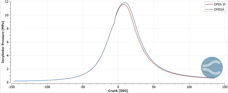
The pressure variation with respect to crank angle provides the optimal condition to initiate the combustion process. High pressure rise indicates slight increase in high temperature and optimal vaporizing time for fuel. From the graph, the omega piston design shows a slight peak rise than open-w piston. With regard to pressure other parameters are also analysed to predict better design of piston.
Mean temperature:
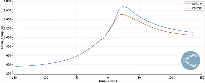
The mean temperature plot provides the peak temperature rise for the combustion process to initiate with respect to crank rotation. The mean temperature is a function of pressure variation. The omega piston shows a maximum scale of 1700K and for open-w piston it is around 1450K. With better temperature release, omega piston design provides combustion reaction mechanism properly and at a faster rate.
Spray penetration length:
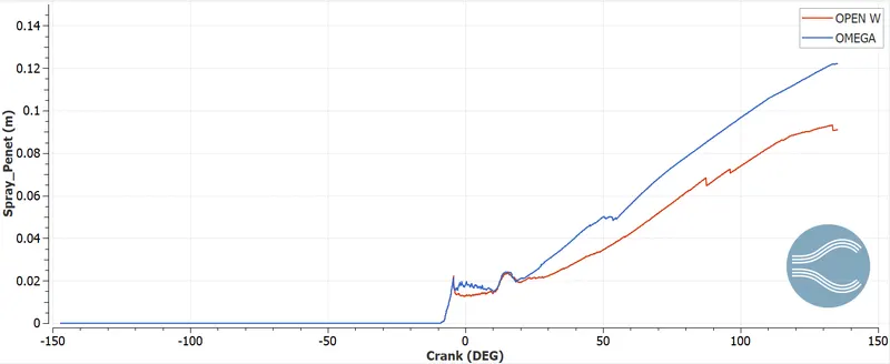
The spray penetration length is another important parameter from design point of view to judge a better combustion process. The spray length determines the vaporization effect of the fuel. From the graph, it is seen that for omega piston design, the spray penetration length is deeper than open-w piston. Proper vaporization of fuel is seen for omega piston whereas a lot of impingement can be seen for open-w piston. This impingement of fuel can result in incomplete combustion process with higher level of unburnt HC and soot formation. From the two-piston design, it can be suggested that omega piston design can produce better combustion efficiency than open-w piston.
Liquid spray:
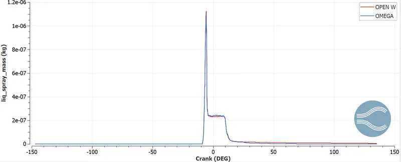
This plot gives the amount o fuel drops that are created during the spray of fuel into the combustion chamber. The drops are lagrangian parcels formed due to vaporization. After the combustion, the graph shows the amount of unburnt hydrocarbon left over.
Heat release rate plot:
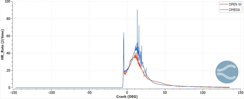
The heat release plot provides the amount of heat released per crank angle. The spike in the plot shows certain disturbances, which can be avoided. The integrated heat release shows the total amount of heat release during the entire cycle of combustion process. This data is obtained by integrating the heat release rate plot. The ratio of the integrated heat and the total energy of the fuel provides the combustion efficiency.
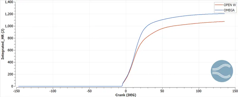
Integrated heat release for open-w piston= 1076.6098J
Integrated heat release for omega piston= 1206.0598J
Difference in heat release= 129.45J
Computing the mass for 129.45J
Calorific value of diesel = 45.5MJ/kg
massoffuel=129.4545.5e6=2.845e−6kgmassoffuel=129.4545.5e6=2.845e-6kg
This is the fuel wasted for omega piston for 1 cycle. If we consider the simulation to run for 1000 cycles, then the amount of fuel wastage is 2.845e-3kg, which is considerably larger.
From the engine calculator data, for half cycle period we find out the estimated work done by two different piston design configurations:
Open-w piston engine calculator
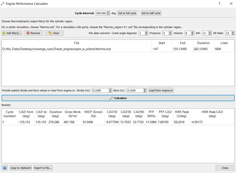
Work done by open-w piston= 481.768J
Duration of combustion for open-w piston= 270.288degree
timetakenforcombustion=(timedegree)⋅durationofcombustion=1.042e−4⋅270.288=0.02816stimetakenforcombustion=(timedegree)⋅durationofcombustion=1.042e-4⋅270.288=0.02816s
Omega engine calculator
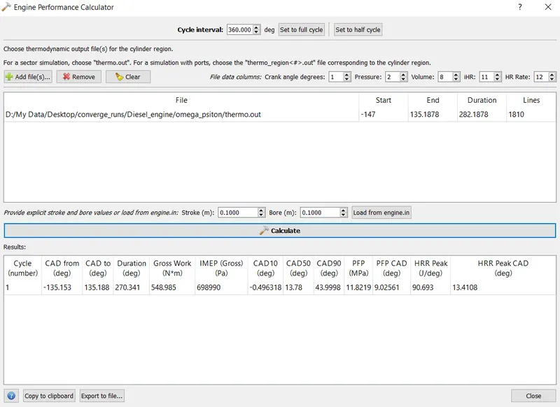
Work done by omega piston= 548.985
Duration of combustion for omega piston= 270.341degree
timetakenforcombustion=(timedegree)⋅durationofcombustion=1.042e−4⋅270.341=0.02816stimetakenforcombustion=(timedegree)⋅durationofcombustion=1.042e-4⋅270.341=0.02816s
So the time taken for combustion for both the piston design is same.
IMEP(Indicated Mean Effective Pressure):
It is the average pressure that is induced in the combustion chamber during the complete thermodynamic cycle.
IMEP foe open-w piston =613406Pa
IMEP for omega piston = 698990Pa
Computing the fuel mass per cycle:
RPM=1600RPM=1600
RPS=160060=26.67RPS=160060=26.67
DEGR∃PERCYCLE=RPS⋅360=9601.2DEGR∃PERCYCLE=RPS⋅360=9601.2
Timeperdegree=1.042e−4Timeperdegree=1.042e-4
Timeper720degree=timeperdegree⋅720=1.042e−4⋅720=0.075Timeper720degree=timeperdegree⋅720=1.042e-4⋅720=0.075
fuelflowrate=3.6e−4kgsfuelflowrate=3.6e-4kgs
fuelmassperCYCLE=fuelflowrate⋅time720=27e−5kgfuelmassperCYCLE=fuelflowrate⋅time720=27e-5kg
Computation of power and torque for two different piston design:
powerforopen−wPISTON=WORKDONEdurationofcombustion=481.7680.02816=17.108kWpowerforopen-wPISTON=WORKDONEdurationofcombustion=481.7680.02816=17.108kW
POWERFOROMEGAPISTON=WORKDONEdurationofcombustion=548.9850.02816=19.495kWPOWERFOROMEGAPISTON=WORKDONEdurationofcombustion=548.9850.02816=19.495kW
Torque of engines
→rqueforOPENWPISTON=P⋅602⋅π⋅N=17.108⋅103⋅602⋅3.14⋅1600=102.157Nm→rqueforOPENWPISTON=P⋅602⋅π⋅N=17.108⋅103⋅602⋅3.14⋅1600=102.157Nm
→rqueforOMEGAPISTON=P⋅602⋅π⋅N=19.495⋅103⋅602⋅3.14⋅1600=116.411Nm→rqueforOMEGAPISTON=P⋅602⋅π⋅N=19.495⋅103⋅602⋅3.14⋅1600=116.411Nm
The power and torque calculation shows that the omega piston is 13.95% higher than open-w piston.
Gaseous fuel plot:
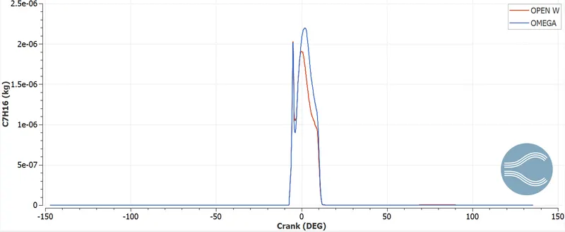
There is a steep increase in omega piston due toits design. This causes significant penetration length which allows to vaporize in high temperature. Whereas a lot of fuel impingement occurs in open-w piston and fuel vaporization does not take place properly. Another advantage of omega piston is that swirl motion takes place, which can be captured in mesh motion. The swirl motion helps in effective vaporization and high flame burning efficiency.
Emission plot:
The emission plot is the output obtained for one cycle of combustion. For more accurate results, more no of simulation runs are preferred collectively and compared.
CO plot:
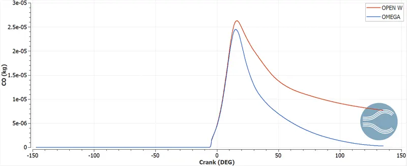
Carbon monoxide is a poisonous gas and which results in formation due to incomplete combustion of fuel. CO results in formation when enough oxygen is not sufficient to convert carbon to CO2. The open-w piston produces more amount of CO than omega piston design. It can be seen that performance parameter can be better estimated for omega piston design. The CO level reaches almost zero for omega piston and for open-w piston it is higher in amount.
CO2 plot:
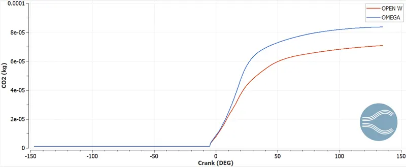
The CO2 is the by-product of combustion. When compared to CO, CO2 emissions are more in omega piston. So the nox emission is more in omega piston. Accordingly design changes or piston modification can be made to reduce the CO2 emission.
Hiroy soot plot:
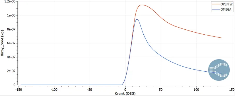
Soot is a by-product pf combustion and is black in colour. It comes out with the exhaust gas and is generally found at the outlet port of combustion chamber. Accumulation of excessive soot results in improper combustion and affects the performance of the engine. The soot level for omega piston is less than open-w piston. This quantifies the amount of CO emission formed at the exhaust. From the given piston design, low soot level formation produces less pollutant and less knocking.
Open w piston Hiroy soot animation
Omega piston Hiroy soot animation
NOx plot:
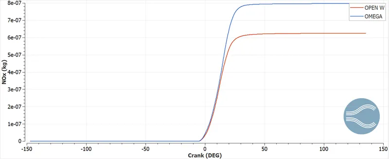
It is another harmful gas emitted after combustion. Diesel engine produces more nitrogen combustion than gasoline engine and hence more NOx levels. This is zeldovich NOx. The performance of open-w piston design is better than omega piston, however soot is higher. Different trade off compared to different piston design will provide better performance and less knocking effect.
Open w piston NOX animation
Omega piston NOX animation
UHC:
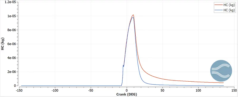
Hydrocarbon are the species which undergoes combustion inside the combustion chamber. The hydrocarbons when left over after combustion results in soot formation. The unburnt hydrocarbon signifies less engine performance according to piston design configuration. From the graphical plot it can be seen that omega piston produces no unburnt hydrocarbon at the outlet, while for open-w piston certain amount of unburnt hydrocarbon is seen to formed. This predicts the combustion efficiency of omega piston higher than open-w piston.
Discussion on selection of best piston design configurations:
- From a sustainable and desirable combustion point of view, it is essential to highlight the performance of two piston design based on the spray length penetration effect. For a better design point of view, it is essential for fuel mass to vaporize completely at the optimal temperature and pressure condition. The spray penetration factor is more profound and deep in case of omega piston design, where only few vaporized droplets are seen after combustion. For open-w piston impingement of fuel is seen, which in turn undergoes incomplete combustion and high unburnt hydrocarbon. Spray penetration factor is important to decide the flame propagation and uniform temperature distribution for the entire cycle of crank rotation.
- Characterizing parameters like pressure, mean temperature, integrated heat release becomes a crucial factor in deciding a better piston design. The omega piston shows a better output in terms of peak pressure, temperature and integrated heat release, which ensures a high work efficiency than open-w piston. In comparing both the piston design, it can be concluded that proper combustion mechanism have been achieved at every crank angle rotation. In case of omega piston there is high chances of producing higher work output than open-w piston configuration.
- After successful simulation run of two different piston design, it is essential to compare the work and the torque parameter. Work output and torque calculations are important from design point of view, to improve the engine performance. Computational readings from the engine performance calculator predicts that omega piston is 14% higher than open-w piston in terms of torque. This is important parameter for design engineers to improve the piston design for omega configuration so that more better work output can be gained.
- From emission modelling analysis trade off in piston design shows a sign of an efficient performance diesel engine. With less nox and soot disposed at the outlet, the better the engine performance considered. In both the piston design, it is verily seen that omega piston have almost zero soot but higher nox emission. But on the other hand, it is completely opposite in case of open-w piston. It is certain to say that knocking tendency will be predominant in omega piston, which can degrade the quality of work to certain extent. But high soot content in open-w piston can increase the chances of accumulated unburnt hydrocarbons and CO gases, which can eventually lead to incomplete combustion and lower work output.
On considering the above discussed points, it can be predicted that omega piston on behalf of all modelling parameters can operate in a more sustainable better way with a high work efficiency. So, design modification can be made for omega piston based on performance and more no of simulation run for higher no of cycles. In this regard omega piston can be considered as best piston design for diesel engine CAT3410.
Conclusions:
- Piston bowl profile and omega profile are been considered to carry out the diesel engine simulation and compare the best design among the two.
- Adaptive mesh refinement with sub grid scaling factor and fixed embedding is done at the injector section to capture the effect of spray phenomenon in a better way.
- Emission modelling with hiroy soot model and nox formation are considered to provide a better decision in piston performance level.
- Omega piston is considered as best design in achieving optimal performance of diesel engine.
- Wan NurdiyanaHi Mr Soudip, can I get your input files especially mech.dat? Thank you